

It is designed for maximum performance. Please seek advice if one is not familiar with this kind
of electric powered precision model. Operating this model without prior preparation may cause
injuries. Remember, safety is the most important thing. Always keep this instruction manual at
hand for quick reference.
Warning ! This model is not a toy.
THE WINGS MAKER
FACTORY PRE-FABRICATED
ALMOST-READY-TO-FLY (ARF) SERIES
MADE IN CHINA
* Specifications are subject to change without notice.*
www thewingsmaker com. .
SpecificationsSpecifications
Before commencing assembly please read these instructions thoroughly , .
INSTRUCTION MANUAL
Wing Span: 36.4 in / 925 mm
Wing Area: 346 sq in / 22.3 sq dm
Flying Weight: 28.3 oz / 800 g
Fuselage Length: 41.5 in / 1055 mm
Requires: 4-channel radio w/ 4 micro servos,
2 x
Outrunner Motor
KM28251025 w/ Propeller Adaptor HW234040R &
HW2340400, 2 x 15A Brushless ESC,8x4E & 8x4P Propeller,
3 cells 11.1V 1800 mAh Li-Po battery & charger.
(
GM070XM
)
GM070XMPO30681411

Check all parts. If you find any defective or missing parts contact your local dealer. Please
DRY FIT and check for defects for all parts that will require CA or Epoxy for final assembly.
Any parts you find to be defective after the gluing process may be difficult to remove for
warranty replacement. The manufacturer will replace any defective parts, but will not extend
to the parts that are good before gluing to defective parts during assembly. Warranty will
not cover any parts modified by customer. For pre-assembled kits, please check proper
functions of all servos on the ground before flying. Servo gears could be damaged when
control surfaces are hit during transportation of models. The manufacturer will replace any
servos due to manufacturer`s defect, but will not cover plane crashes due to damaged
servos not detected before flying.
Symbols used throughout this instruction manual comprise of the following :-
Read through the manual before you begin, so you will have an overall idea of what to do.
1
2
3
INDEX
BEFORE YOU BEGIN
BEFORE YOU BEGIN
PARTS LIST
ASSEMBLY
SAFETY PRECAUTIONS
P.1
P.2
P.3-P.11
P.12
P.1
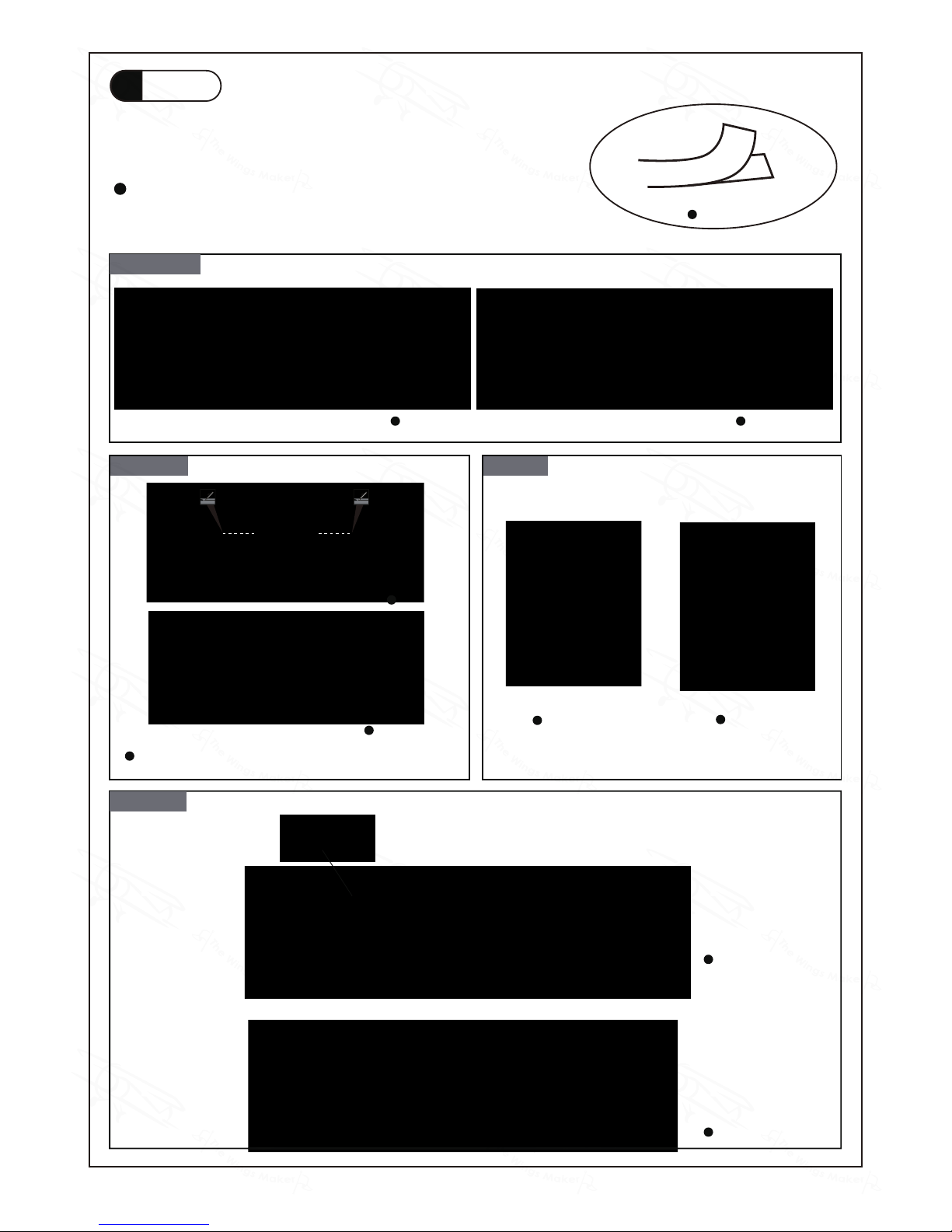
Cut off shaded portion.
Ensure smooth non-binding
movement while assembling.
Apply instant glue
(C.A.glue, super glue.)
Assemble left and right
sides the same way.
Peel off shaded portion
covering film.
Pay close attention here!
Apply epoxy glue.
Must be purchased separately !
Drill holes with the specified
diameter (here: 3mm).
Pierce the shaded portion
covering film.
3mm
Do not overlook this symbol !
Warning!
Apply thread locker
GM070XMPO30681411

P.2
Parts List
1.DECALS: GM070XM DEC -- 1 set
MAIN WING -- 1 pair
STABILIZER & ELEVATOR -- 1 set
VERTICAL FIN & RUDDER -- 1 set
FUSELAGE -- 1 set
BATTERY COVER -- 1 set
2.HINGES PL4115050 -- 4 pcs
3.HINGES PLL4115050-- 3 pcs
4.DECALS FOR RUDDER - 1 set
5.HORN PL4113103 -- 1 pc.
SERVO MOUNT -- 2 pcs
6.FUEL TUBE D2xD4x4mm -- 2 pcs
CLEVIS PL4112105 --1 pc.
STRAPER PL4112106 -- 1 pc.
PUSHROD Ø1.4x125mm w/ Threads (For Rudder) -- 1 pc.
7.HORN PL4113103 -- 1 pc.
SERVO MOUNT -- 2 pcs
8.FUEL TUBE D2xD4x4mm -- 2 pcs
CLEVIS PL4112105 --1 pc.
STRAPER PL4112106 -- 1 pc.
PUSHROD Ø1.4x50mm w/ Threads (For Elevator) -- 1 pc.
9.TAIL LANDING GEAR --1 set
SCREW PA2x10mm -- 2 pcs
TAIL WHEEL Ø23mm PL3510230 -- 1 pc.
10.MAIN LANDING GEAR Ø2.5mm -- 1 set
COLLAR Ø2.6mm w/ Set Screw -- 2 sets
MAIN WHEEL Ø40mm PL3116040 -- 2 pcs
SCREW PM2x14mm -- 1 pc.
M2 NYLON INSERT LOCK NUT -- 1 pc.
WASHER d2xD5mm -- 2 pcs
PLYWOOD 21x40x2.5mm (For Main Landing Gear) -- 1 pc.
11.NOSE PIECE -- 1 pc.
12.HORN PL4113103 -- 2 pcs
HINGES PLL4115050-- 8 pcs
SERVO MOUNT -- 4 pcs
13.FUEL TUBE D2xD4x4mm -- 4 pcs
CLEVIS PL4112105 --2 pcs
STRAPER PL4112106 -- 2 pcs
PUSHROD Ø1.4x76mm w/ Threads (For Aileron) -- 2 pcs
14.PLYWOOD 30x60x4mm (L)(For Motor) -- 1 pc.
PLYWOOD 30x60x4mm (R)(For Motor) -- 1 pc.
SOCKET HEAD SCREW M3x8mm -- 8 pcs
WASHER d3xD7mm -- 8 pcs
8x4E PROPELLER PL6210804 -- 1 set
8x4P PROPELLER PL6210804P -- 1 set
15.WING TUBE Ø6x365mm -- 1 pc.
SCREW PM3x20mm -- 2 pcs
BATTERY TIE 180mm-- 1 pc.
BATTERY MAT 2x50x150mm-- 2 pcs
GM070XMPO30681411
P.3
Decals
1
Bottom ViewTop View
Cut out decal sheet, peel off backing sheet and
apply on fuselage, stabilizer and wings.
Decal
Main wings
Bottom View
Top View
Left View
Left View
Right View
Right View
Stabilizer Rudder
Fuselage
After applying the thunderbolt decals across the hinge line,
cut it to allow free movement of the Stabilizer.
GM070XMPO30681411

Hinge Setting
P.4
Stabilizer & Elevator
2
Vertical Fin & Rudder
3
Decals for Rudder
4
Hinge
Bottom View
Hinge
Section View Completed
Hinge Setting
Hinge
Section View Completed
For pre-assembled version, the hinges are factory glued.
For pre-assembled version, the hinges are factory glued.
Right View
Hinge
After applying the thunderbolt decals across the hinge line,
cut it to allow free movement of the Rudder.
GM070XMPO30681411
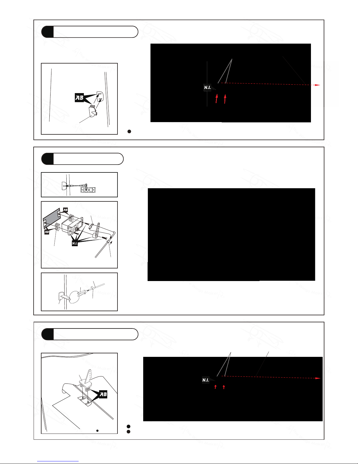
Horn
P.5
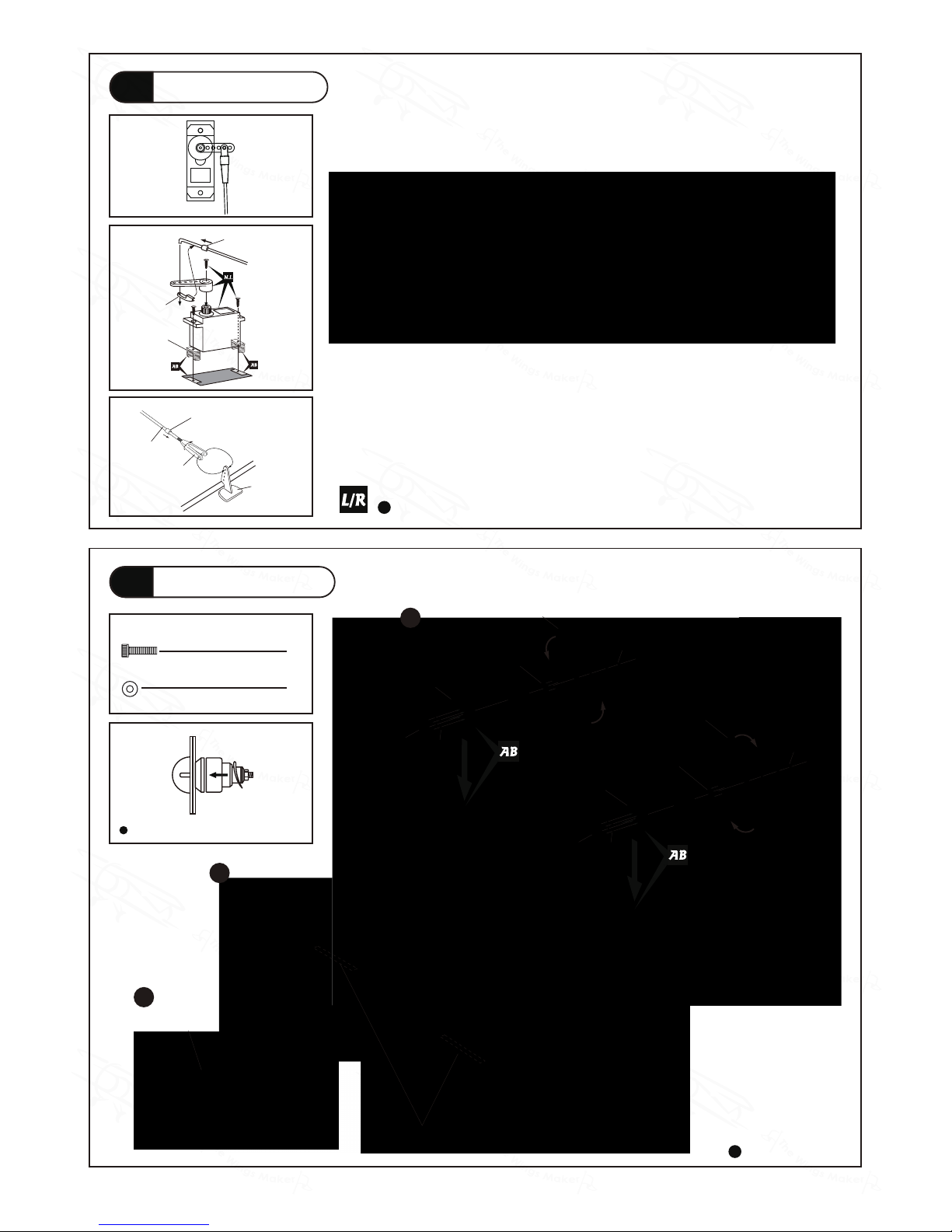
Elevator Servo & Horn
7
Rudder Servo & Horn
5
Rudder Pushrod
6
Clevis
Pushrod
Ø1.4x125mm
Horn
Fuel Tube
d2xD4x4mm
Servo wire
Servo wire
Plastic Bracket
Plastic Bracket
Servo Mount
Straper
Fuel Tube
d2xD4x4mm
For pre-assembled version, the horn is factory glued and servo installed.
For pre-assembled version, the horn is factory glued and servo installed.
Horn
Bottom View
Bottom View
GM070XMPO30681411
Bottom View
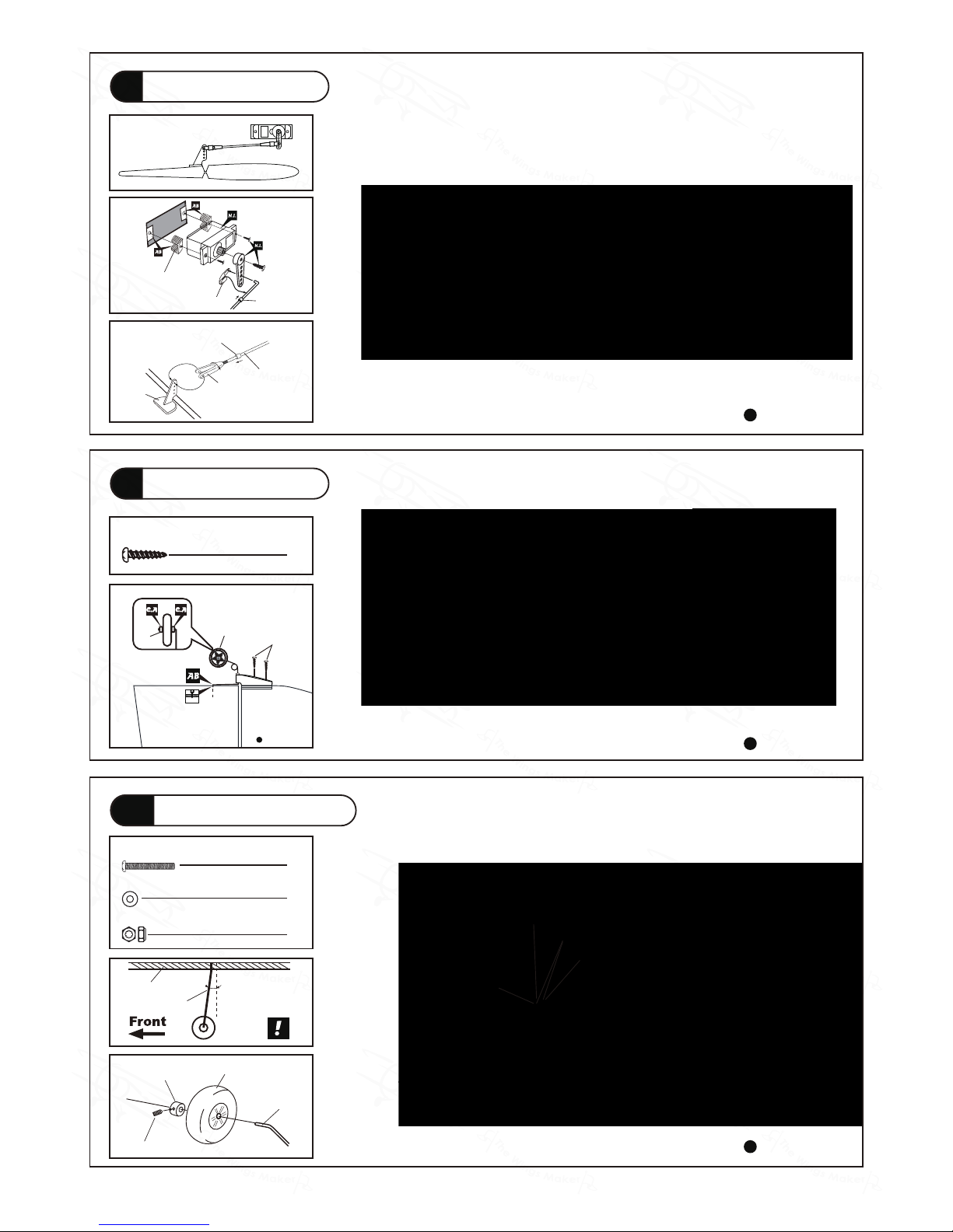
Wheel Ø23mm
PA2x10mm
Plastic
Collar
1.2mm
P.6
Elevator Pushrod
8
Tail Landing Gear
9
Main Landing Gear
10
PA2x10mm Screw
2
PM2x14mm Screw
1
d2xD5mm Washer
2
M2 Nylon Insert Lock Nut
1
Bottom View
Bottom View
Bottom View
10
0
Landing Gear
Fuselage
M3x3mm Set Screw
2.6mm Collar
Wheel Ø40mm
Landing Gear
PM2x14mm
d2xD5mm Washer
M2 Nylon Insert Lock Nut
Plywood
26x40x2.5mm
Clevis
Pushrod
Ø1.4x50mm
Horn
Fuel Tube
d2xD4x4mm
Plastic Stand
Straper
Fuel Tube
d2xD4x4mm
GM070XMPO30681411

Hinge Setting
Hinge
Section View Completed
P.7
Nose Piece
11
Aileron Servo & Horn
12
Servo Mount
For pre-assembled version, the hinges and horn are pre-glued, and servo installed.
Bottom View
Hinge
Horn
Bottom View
Servo Mount
GM070XMPO30681411
8
d3xD7mm Washer
8
Bottom View
Bottom View
P.8
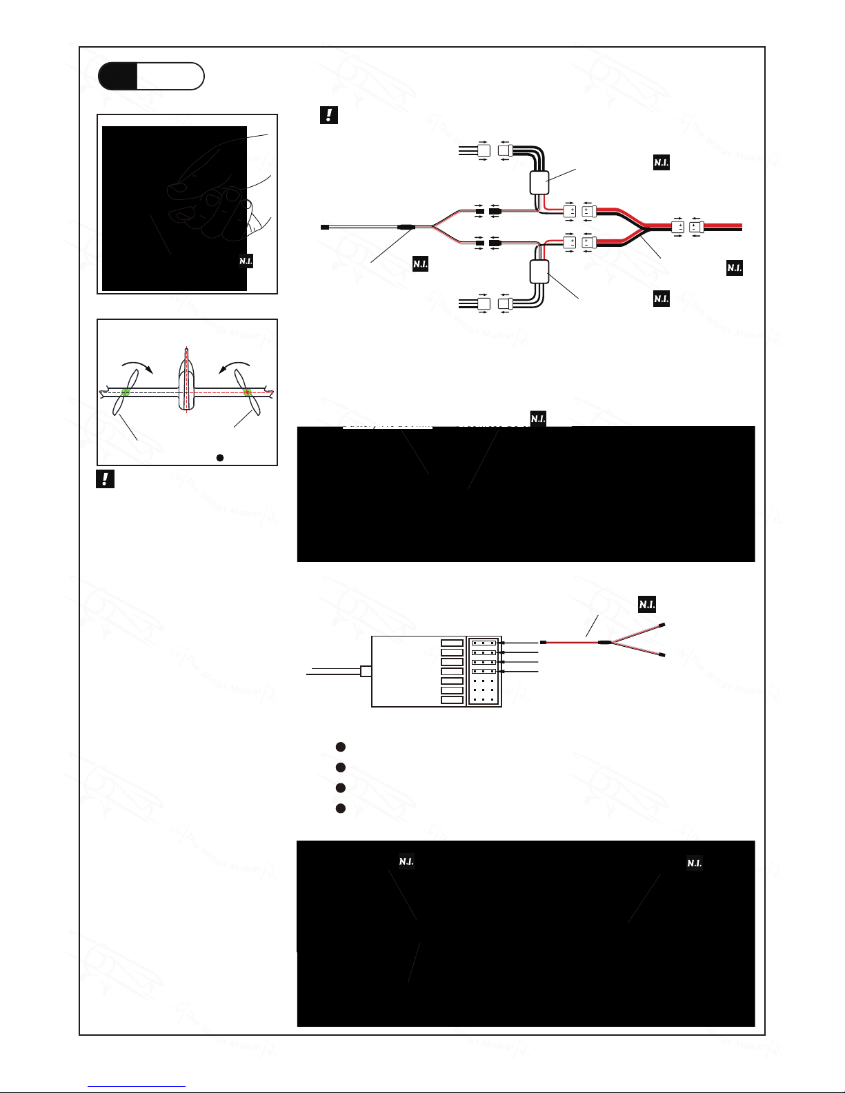
Motor Installation
14
Aileron Pushrod
13
Clevis
Pushrod
Ø1.4x76mm
Horn
Fuel Tube
d2xD4x4mm
Plastic Stand
Straper
Fuel Tube d2xD4x4mm
M5 Nut
M3x8mm
d3xD7mm
Plywood 30x60x4mm(L)
M3x8mm
d3xD7mm
Plywood 30x60x4mm(R)
M5 Nut (Reverse)
8x4E Propeller PL6210804
8x4P Propeller PL6210804P
Propeller Adaptor HW2340400
Propeller Adaptor HW234040R
M3x8mm
Socket Head Screw
1
2
3
Decal for Motor Plywood
Cut unprinted section of decal
sheet to tape motor wires in groove.
The propellers should curve to the front.
GM070XMPO30681411

PM3x20mm Screw
2
PM3x20mm
P.9
Main Wing
15
Insert carbon fiber wing tube into right wing, align the anchor holes and apply the PM Screw.
Insert the right wing into the Fuselage. Inset the left wing onto the carbon wing tube, press
the wings against the fuselage align the anchor holes and apply the PM Screw.
PM3x20mm
Wing Tube
Ø6x365mm
GM070XMPO30681411
P.10
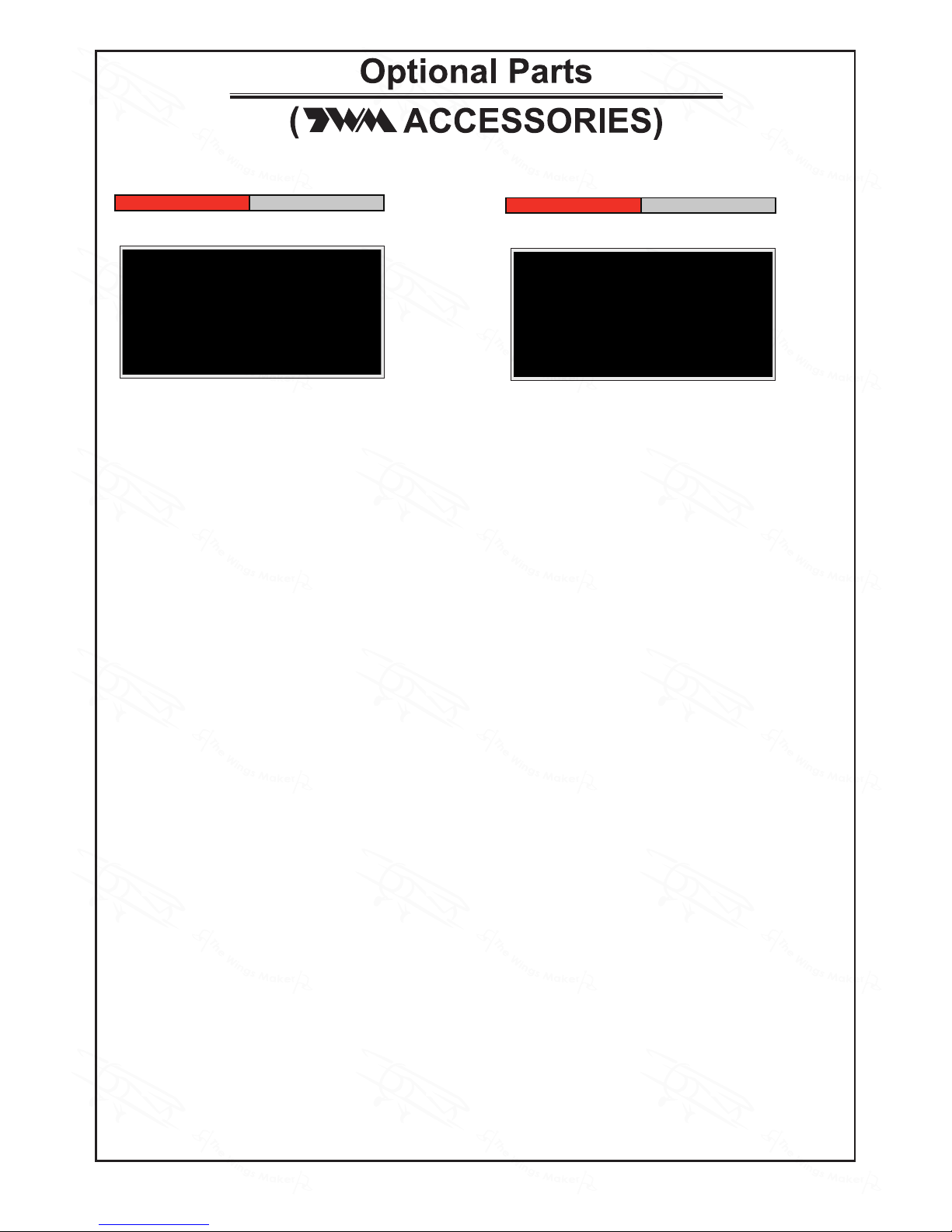
Radio
16
Plug in with red+ / black- reversed will damage the ESC.
Battery Tie 180mm Brushless ESC
Battery Tie 180mm
Brushless ESC
Motor
Receiver
Battery
Motor
ESCESC
Brushless ESC
Brushless ESC
180mm Y-Cord
EZ Power Y-Cord For Twin ESC
KW1210060
EZ Connector Puller
Plug in the Aileron Servos wire to channel 1
Plug in the Elevator Servo wire to channel 2
Plug in the ESC Throttle wire to channel 3
Plug in the Rudder Servo wire to channel 4
1
2
3
4
5
6
ID
SET
Aileron Servo (L)
180mm Y-Cord
Aileron Servo (R)
Rudder Servo
Receiver
Elevator Servo
ESC
Battery Mat
Battery
Receiver
8x4E Propeller PL6210804
8x4P Propeller PL6210804P
Pilot View
8x4E prop. should be on the
left wing, rotating clockwise. 8x4P
prop. should be on the right wing,
rotating counter-clockwise. If you
are using the 3-pin EZ connectors,
unplug, rotate 180º and plug back
will reverse rotating direction of
the motor. For other plugs, interchange any two of the three motor
wires connection will reverse the
rotating direction. Never reverse
the battery connection to the ESC,
they must be red to red (+) and
black to black ( - ) or the ESC will
be damaged.
Connect the three motor wires of the left motor to the left ESC, and right motor to the right ESC.
Connect the throttle control wires of the two ESCs to the Y-chord. The single output plug of the
Y-chord should be connected to the throttle channel of the receiver to control the throttle. Connect
the power input plugs of the two ESCs to the EZ Power Y-Chord, the single output plug of the EZ
Power Y-Chord should be connected to the battery before flying. ( The same procedure applies to
other types of connectors. )
GM070XMPO30681411

P.11
Battery Cover
17
Control Throws
18
C.G.
19
Elevator
Rudder
Ailerons
Adjust the control throws as shown in
the diagram. These throws are good for
general flying. You can adjust according
to your personal preference.
40mm
40mm
50mm
50mm
60mm
60mm
The ideal C.G. position is 120mm (4.7 in.) behind the leading edge
measured at where the wing meets the fuselage. In order to obtain
the C.G. specified, add weight to the fuselage or move the battery
position. Check the C.G. before flying.
120mm
4.7 in.
C.G.
http://www.thewingsmaker.com/instructionManuals.php
GM070XMPO30681411

P.12
Important Safety Precautions
# First time flyer should never fly by himself / herself. Assistance from experienced flyer
is absolutely necessary.
# Pre-flight adjustment must be done before flying, it is very dangerous to fly a badly
pre-adjusted aircraft.
# is specially designed to be powered by
KM28251025
Outrunner Motor.
# Make sure the air field is spacious, never fly the plane too close to people and never get
too close to a running propeller. Extreme caution should be exercised when working with
electric powered models. Make sure the propeller is cleared of all objects, especially your
hands before connecting the battery to the model. Make sure you understand the
operation of the ESC (Electronic Speed Control) by studying the ESC manual. Once you
plug in the battery for electric powered model, always treat the propeller as a rotating one,
as accidental movement of the throttle stick will spin the propeller and could cause injuries.
# Check and re-tighten up all factory assembled screws, use thread locker if necessary.
Warning!
GM070XMPO30681411

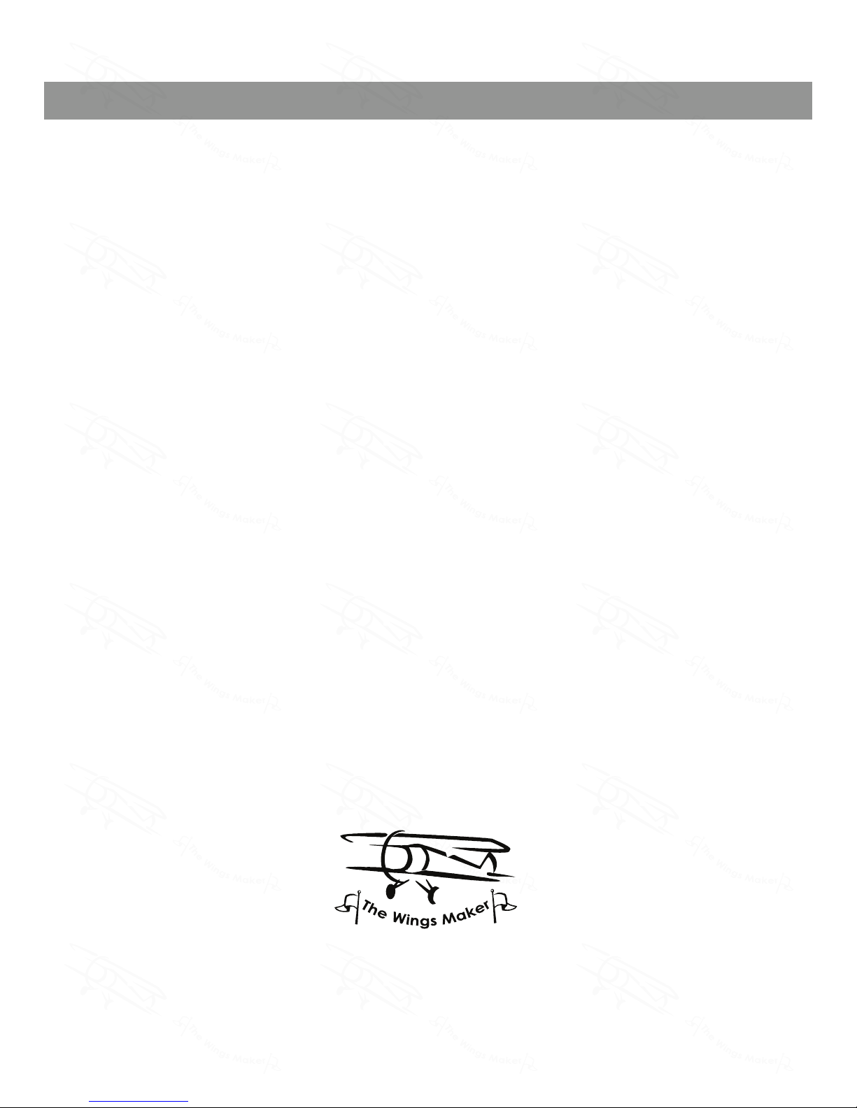
Large Clevis
Small Clevis
Pl8210010
180mm Y-Cord
Code No. Size Package
KW0021800 180mm 1 pc
EZ Power Y-Cord For Twin ESC
Code No. Size Package
KW1210060 1 pc
Outrunner Motor
KM28251025
-Kv (rpm/V): 1025
-Operating Power: 110W
-Operating Voltage: 2-3S Li-Po
-Operating Current: 10A
-Peak Current: 15A (max. 15 sec.)
-Internal Resistance: 50 m ohms
-Diameter: 27.6mm
-Length: 25mm
-Weight: 40g
-Shaft Diameter: 3mm
-Shaft Length: 14 mm
-Mounting Screw:
M3 (Front)
-Distance of Mounting Holes:
16mm and 19mm
EZ Connector Puller
Code No. Size Package
PL8210030 1 set
GM070XMPO30681411
8x4E Propeller
Code No. Size Package
PL6210804 1 pc
8x4P Propeller
Code No. Size Package
PL6210804P 1 pc
GM070XMPO30681411
THE WINGS MAKER
www.thewingsmaker.com
GM070XMPO30681411
 Loading...