

The Whistler Group TP01 User Manual

OWNER’S MANUAL
Model TS-104
WIRELESS TIRE PRESSURE AND
TEMPERATURE MONITORING SYSTEM
tirescout.qxp 3/12/2012 10:34 AM Page 1

INTRODUCTION
If you have questions concerning the
operation of this Whistler product please call:
CuSTOmer SeRVICE
1-800-531-0004
Monday - Friday • 8:00 am - 5:00 pm CT USA
or visit our website
www.whistlergroup.com
Please keep the receipt in a safe place. You may register your
product online
at www.whistlergroup.com. For warranty
verification
purposes, a copy of your dated store receipt must still accompany
any unit sent in for warranty work. If the unit is returned without a
dated store receipt an out of warranty service charge applies.
Note: Your warranty period begins at the time of purchase. The
warranty is validated only by the dated store receipt! Now is the
time to record the serial number of the unit in the space provided
in the warranty section of the manual.
tirescout.qxp 3/12/2012 10:34 AM Page 2

Product Features 3 - 4
• System Components . . . . . . . . . . . . . . . . . . . . . . . . . . . 3
• Button Callouts and Icons . . . . . . . . . . . . . . . . . . . . . . . 4
Installation 5 - 7
• Sensor Location . . . . . . . . . . . . . . . . . . . . . . . . . . . . . . 5
• Sensor Battery Installation . . . . . . . . . . . . . . . . . . . . . . 5
• Sensor Installation . . . . . . . . . . . . . . . . . . . . . . . . . . . . 5
• Monitor Installation . . . . . . . . . . . . . . . . . . . . . . . . . . . 6
• Power Cord Connection . . . . . . . . . . . . . . . . . . . . . . . . . 7
• Turning the Monitor ON or OFF Manually . . . . . . . . . . . . 7
Operation 8 - 15
• Factory Default/Settings Mode . . . . . . . . . . . . . . . . . 8 - 9
• Adjusting the Alerts . . . . . . . . . . . . . . . . . . . . . . . . 9 - 10
• Alerts . . . . . . . . . . . . . . . . . . . . . . . . . . . . . . . . . 11 - 12
High Pressure Alert . . . . . . . . . . . . . . . . . . . . . . . . . . 11
Low Pressure Alert . . . . . . . . . . . . . . . . . . . . . . . . . . 11
High Temperature Alert . . . . . . . . . . . . . . . . . . . . . . . 12
Fast Leakage Alert . . . . . . . . . . . . . . . . . . . . . . . . . . 12
Sensor Low Battery Alert . . . . . . . . . . . . . . . . . . . . . 12
• Monitor Display Information . . . . . . . . . . . . . . . . . 13 - 14
Monitor Sleep Mode . . . . . . . . . . . . . . . . . . . . . . . . . 13
Backlighting . . . . . . . . . . . . . . . . . . . . . . . . . . . . . . . 13
Charging the Monitor . . . . . . . . . . . . . . . . . . . . . . . . 14
• Replace the Transmitter Battery . . . . . . . . . . . . . . . 14 - 15
Troubleshooting 16
FCC Information 16
Warranty Information 17 - 19
Specifications 19
TABLE OF CONTENTS
tirescout.qxp 3/12/2012 10:34 AM Page 3
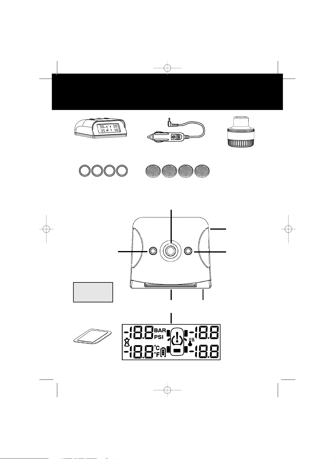
SYSTEM COMPONENTS
Monitor
Power Cord
Sensor
(4 Included)
Spare water-proof
rubber seals
1
2
3
4
5
6
3
Double sided tape
Dash Pad
CR 1632 Batteries
tirescout.qxp 3/12/2012 10:34 AM Page 4
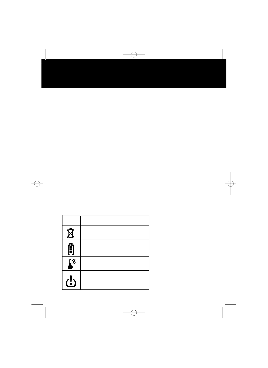
Icon Description
TX Low Battery Indicator
Monitor Battery Indicator
High Temperature
Faulty Pressure
BUTTON CALLOUTS & ICONS
Whistler’s ergonomic and user-friendly design provides a new
level of operating convenience. Special features include:
1. Backlit LCD Display – Shows tire and battery
information.
2. Left Button – Dual function button. Press and hold to
power on the monitor. Quick press selects a “Down”
function while in a setting mode.
3. Middle Button/Alert Light – Button illuminates red
during an alert condition. Quick press mutes the alert audio.
Press and hold enters setting mode. Press this button while
in a setting mode selects a “SET” function.
4. Power Jack – For connection with the supplied power
cord.
5. Right Button – Quick press selects a “UP”
function while in a setting mode.
6. Speaker – Provides alert warning tones.
4
tirescout.qxp 3/12/2012 10:34 AM Page 5
INSTALLATION
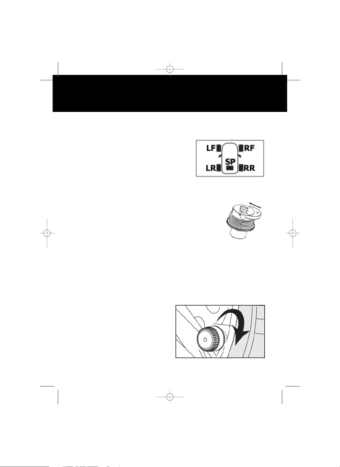
Sensor Location
The factory has already set up the codes for the 4 sensors
which are provided and matched with
the monitor, and each sensor is
marked with the corresponding tire
position [LF, RF, LR, RR, SP (spare
tire)]. Install each sensor in the correct
tire position as per the diagram.
Sensor Battery Installation
1. Unscrew the sensor cap.
2. Insert battery into sensor ensuring that the
positive “+” is facing up.
3. Replace the sensor cap.
Repeat for the remaining sensors.
Sensor Installation
1. Unscrew the tire valve cap and mount the tire sensor in its
place.
2. Save the tire valve cap in the vehicle’s storage
compartment. Important: Only hand tighten the sensor
cap to prevent possible damage to the sensor.
CAUTION:
After proper sensor installation, it is
highly recommended to check for any
air leakage. Test by spraying soapy
water on the valve stem and look for
bubbles. No bubbles, no leaks.
Retighten if bubbles appear.
5
tirescout.qxp 3/12/2012 10:34 AM Page 6

INSTALLATION
Monitor Installation
1. Secure the monitor inside the vehicle cabin without
obstructing the driver's vision of the road.
2. Place the monitor on the dashboard using the Dash Pad or
the double-sided tape. If using the double sided tape make
sure that the area choosen is clean and dry. Clean with
isopropyl alcohol, if necessary, to remove any waxes or
polishes.
3. Plug the power adapter into the cigarette lighter; turn the
monitor on to fully charge.
(It must be charged more than 2.5 hours the first time).
CAUTION:
1. The monitor should be installed inside the vehicle where it
does not affect normal driving.
2. The monitor should be securely placed to avoid falling off
during driving.
3. After the system is installed correctly, the driver does not
need to check the monitor while driving. Alerts will be
issued when abnormal conditions are found in the tires.
6
tirescout.qxp 3/12/2012 10:34 AM Page 7
 Loading...