

The Whistler Group SC11 User Manual
DIGITAL TRUNKING
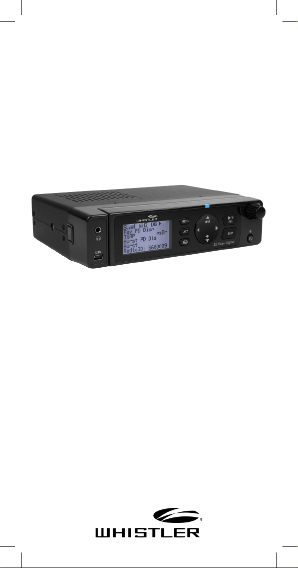
Desktop/Mobile
EZ Digital Scanner
OWNER’S MANUAL
WS1095

TABLE OF CONTENTS
Introduction ..................................................... 4
What is Object Oriented Scanning? .......................... 4
Features ......................................................................... 5
Package Contents ........................................................ 5
Scanning Legally .......................................................... 6
FCC Statement .............................................................. 7
Setup .................................................................. 8
Antenna ......................................................................... 8
Earphones, Headphone and Speakers ...................10
Listening Safely ...........................................................10
Feature Description ....................................................11
Attaching Remote and Base Unit ............................12
Keypad ............................................................ 14
Understanding the Keypad .......................................14
Rotary Encoder ............................................................16
Display ............................................................ 18
Understanding the Display .......................................18
Display Icons ............................................................... 20
Desktop Operation .....................................................22
Mobile Operation ...................................................... 24
Turning On .................................................................. 26
Program Methods ...................................................... 27
Setting Location ......................................................... 28
Power Up Password ................................................... 31
EZ Scan Library .............................................. 32
Installing EZ Scan Software ..................................... 34
Library Updates ......................................................... 34
Manual Programming ............................................... 35
EZ Scan Library Notes ............................................... 36
Library Structure ........................................................ 36
Editing Objects Manually ......................................... 37
Alert LED Setting ........................................... 39
Recording/Playback .................................................. 44
Internal Clock/Calendar ........................................... 45
Time Display ............................................................... 46
Scanning ......................................................... 47
Monitoring and Scanning ........................................ 47
Frequency or Talkgroups .......................................... 47
Active Scanlists .......................................................... 47
2

TABLE OF CONTENTS
Enable/Disable Scanlists .......................................... 47
Lock Out Objects ........................................................ 47
Skip Transmission ....................................................... 48
Rename Scanlists ....................................................... 48
Set Priority Objects ................................................... 48
Scanlists and Scan Sets ................................ 49
Searching ....................................................... 51
Using Spectrum Sweeper ......................................... 51
Perform a Service Search ......................................... 51
Perform a Limit Search ............................................. 52
To Save Found Frequencies ..................................... 52
Search Settings ............................................. 53
Spectrum Sweeper ..................................................... 53
Service Search ............................................................ 53
Limit Search ................................................................ 53
Saving Found Codes ................................................. 54
Weather Monitoring ..................................... 55
FIPS Codes ................................................................... 55
SAME Standby Modes ............................................... 56
Weather Priority ......................................................... 56
SKYWARN™ .................................................... 56
Conguring .................................................... 57
Using V-Scanner Storage .......................................... 57
Conguration Settings (EZ Scan) ............... 58
Using EZ Scan Software ............................................ 60
DSP Firmware Update ............................................... 60
Maintenance .................................................. 61
Troubleshooting/Error Messages ........................... 61
Birdie Frequencies ..................................................... 61
Library Copyright Notice ............................. 62
Frequency Coverage ..................................... 63
Specications ................................................ 64
Consumer Warranty ..................................... 66
3

INTRODUCTION
Introduction
Scanning technology has changed dramatically over
the years. The WS1095 scanner with Object Oriented
User Interface is designed to help the hobbyist build a
collection of channels to scan:
• Start small and expand
• Organize channels and talkgroups
• Remove unwanted channels and talkgroups
What is Object Oriented Scanning?
Programming scanning receivers can be challenging,
but object-oriented programming simplifies the
process by using common conventions for scanning
concepts that have common characteristics.
A Scannable Object is any defined item that can be
scanned or monitored, including:
• Conventional, non-trunked radio frequencies
• Talkgroups used on a trunked radio system
• Radio services
• Defined searches
Because scannable objects are defined by the same
basic elements, the Object Oriented User Interface
(OOUI) is designed to simplify scanning by managing
all scannable objects similarly. When you learn how to
program one type of object, you can program other
types of scannable objects as well.
4

FEATURES
Features
• Simple keypad and display
• USA/Canada RadioReference database on SD Card
• Quick Location based Programming (City, Zip, County)
• Detects and masks encrypted voice audio
• Decodes RadioID/TalkgroupID data
• Database Upgradeable CPU Firmware, DSP
Firmware and Database Library
• USB Interface 2.0 or earlier
• Improved P25 Functionality (Phase II, X2-TDMA)
• PC Software to customize your WS1095 settings
• Detachable Remote Control Head w/ Magnet Mount
• Signal Strength Meter
• 200 Scanlists
• Weather Radio Functions
• Multi–system Trunking
• Spectrum Sweeper
• Headphone/Speaker Jacks
• Programmable Alert LED
• Programmable Audio Alarms
• V-Scanner II Storage System
• Audio Recording
• Built-in Clock/Calendar
• Built-in Services Searches
Package Contents
• Desktop/Mobile Scanner with Remote Head
• Pull up BNC Antenna
• USB Cable
• SD Card (Installed in the Scanner)
• User’s Guide
• Quick Start Guide
• PC Software included on SD Card
• DC Power Cable
• Special 6½ ft. LAN Cable for Remote Head
• Mounting Bracket and Hardware Kit
• AC Adapter
• Remote Head Mounting Bracket and Screws
5

SCANNING LEGALLY
Scanning Legally
Your scanner covers frequencies used by many
different groups including police and fire
departments, ambulance services, government
agencies, private companies, amateur radio services,
military operations, pager services, and wireline
(telephone and telegraph) service providers. It is legal
to listen to almost every transmission your scanner
can receive. However, there are some transmissions
you should never intentionally listen to.
These include:
• Telephone conversations (cellular, cordless, or other
means of private telephone signal transmission)
• Paging transmissions
• Any intentionally decoded scrambled or encrypted
transmissions
According to the Electronic Communications Privacy
Act (ECPA), you are subject to fines and possible
imprisonment for intentionally listening to, using, or
divulging the contents of such a transmission unless
you have the consent of a party to the communication
(unless such activity is otherwise illegal). This scanner
has been designed to prevent reception of illegal
transmissions. This is done to comply with the legal
requirement that scanners be manufactured so as to not
be easily modifiable to pick up those transmissions.
Do not open your scanner’s case to make any
modifications that could allow it to pick up
transmissions that are illegal to monitor. Doing so
could subject you to legal penalties. We encourage
responsible, legal scanner use. In some areas, mobile
use of this scanner is unlawful or requires a permit.
Check the laws in your area. It is also illegal in many
areas to interfere with the duties of public safety
officials by traveling to the scene of an incident
without authorization.
6

FCC STATEMENT
The FCC Wants You To Know
This equipment has been tested and found to comply
with the limits for a scanning receiver, pursuant to
Part 15 of the FCC Rules. These limits are designed
to provide reasonable protection against harmful
interference in a residential installation. This
equipment generates, uses and can radiate radio
frequency energy and, if not installed and used in
accordance with the instructions, may cause harmful
interference to radio communications.
However, there is no guarantee that interference will
not occur in a particular installation. If this equipment
does cause harmful interference to radio or television
reception, which can be determined by turning the
equipment o and on, the user is encouraged to try
to correct the interference by one or more of the
following measures:
• Reorient or relocate the receiving antenna.
• Increase the separation between the equipment
and receiver.
• Connect the equipment into an outlet on a circuit
dierent from that to which the receiver is connected.
This device complies with Part 15 of the FCC Rules.
Operation is subject to the following two conditions:
1. This device may not cause harmful interference.
2. This device must accept any interference
received, including interference that may cause
undesired operation.
WARNING: Changes or modications to this unit
not expressly approved by the party responsible for
compliance could void the user’s authority to operate
the equipment.
7
CONNECTING ANTENNA
Setup
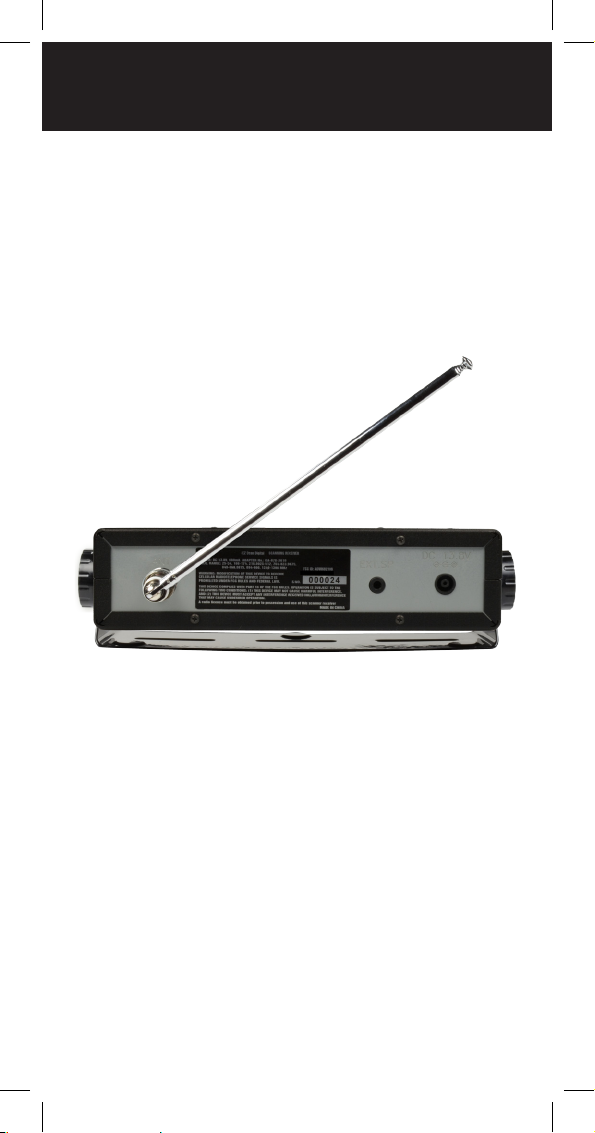
Antenna
To connect the included antenna:
1. Align the slots around the antenna’s connector
with the tabs on the antenna jack.
2. Press the antenna down over the jack and turn the
antenna’s base clockwise until it locks into place.
3. Mobile use requires an external antenna.
You can use a variety of antennas. To connect an
external antenna, follow the installation instructions
supplied with the antenna. Always use 50-ohm coaxial
cable, such as RG-58 or RG-8 low-loss dielectric coaxial
cable. You may also need a BNC adapter.
8

CONNECTING ANTENNA
WARNING: Use extreme caution when installing or
removing an outdoor antenna. If the antenna starts
to fall, let it go! It could contact overhead power
lines. If the antenna touches a power line, touching
the antenna, mast, cable, or guy wires can cause
electrocution and death. Call the power company to
remove the antenna. DO NOT attempt to do so yourself.
WARNING: Outdoor antennas must be properly
grounded to prevent static buildup and lightning
damage. Article 810 of the National Electrical
Code, ANSI/NFPA 70, provides information about
proper grounding of the antenna mast, connection
of coaxial cable to an lightning arrestor, size of
grounding conductors, location of the lightning
arrestor and connection of grounding conductors to
grounding electrodes.
Disconnect your radio from the outdoor antenna
during electrical storm activity to prevent damage.
9

EARPHONES, HEADPHONES, SPEAKER
Connecting an Earphone or Headphones
For private listening, you can plug an 1/8-inch (3.5 mm)
mini-plug earphone or headphones (not supplied) in
the Headphone jack on the front of the WS1095. This
automatically disconnects the internal speaker.
Connecting an Extension Speaker
In noisy areas, or if you install the scanner in a vehicle,
an extension speaker (not supplied) may provide more
comfortable listening. Plug the speaker cable’s 1/8 inch
(3.5mm) mini-plug into your scanner’s EXT. SP jack,
located on the rear panel of the radio.
Listening Safely
To protect your hearing, follow these guidelines when
you use headphones:
• Do not connect headphones to the external speaker
jack located on the rear panel of the radio.
• Set the volume to zero before putting on
headphones. With the headphones on, adjust the
volume to a comfortable level.
• Avoid increasing the volume once you set it. Over
time, your sensitivity to a volume level decreases, so
volume levels that do not cause discomfort might
damage your hearing.
• Avoid or limit listening at high volume levels.
Prolonged exposure to high volume levels can cause
permanent hearing loss.
Trac Safety
Wearing headphones while operating a motor vehicle
can create a trac hazard and is illegal in most areas.
Even though some headphones let you hear some
outside sounds when listening at normal volume
levels, they still can present a trac hazard. Exercise
extreme caution!
10
FEATURE DESCRIPTION
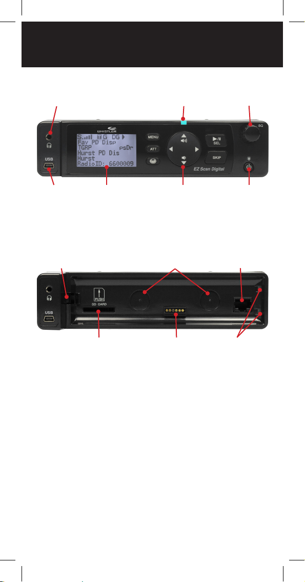
Getting Familiar With Your WS1095
Headphone
Jack
Alert LED
Rotary
Encoder
USB
Connector
LCD
Display
WS1095 Base Unit
Remote Head
Latch
SD Card Slot
Keypad Power
Magnet
Sockets
Remote Head
Connector
Remote Head
Attachment Slots
Button
LAN Cable
Jack
11

ATTACHING REMOTE AND BASE UNIT
Detaching and Attaching Remote
Head and Base Unit
To detach the (Remote Head Unit) from the (Base Unit),
turn the scanner o then press and hold the release
button on the left side of the base unit. A gap will
appear between the base unit and the remote head
unit. Grasp the remote head and carefully remove it
from the base unit.
To link the base unit and remote head unit, connect
them using the supplied 8P8C Type B Straight Cable.
To reattach the remote head to the base, unplug the
LAN cable from both units and align the guide pins
on the right side of the remote head with the slots on
the base unit. Then, carefully press the remote head
into the base unit, keeping your ngers out of the gap
between the remote head and the base. The magnets
will “grab”, holding the remote head in place. The
remote head unit can be attached to an AMPS mount
(not included) if desired.
Base Unit
Press Here
WARNING: Always install the remote head with care,
keeping your ngers clear; the magnets are very
powerful. Always keep the magnets well away from
persons wearing electrical medical devices such as
pacemakers, as the magnets may cause the devices to
malfunction, endangering the wearer’s life.
Remote Head
12

ATTACHING REMOTE AND BASE UNIT
Always keep the magnets well away from
magnetic media such as discs and tapes, and from
magnetically sensitive equipment such as computer
monitors and watches to avoid deleting data or
damaging the equipment.
The rare earth magnets can be damaged by heat;
avoid temperatures greater than 175 degrees
Fahrenheit (80 degrees Celsius), such as in parked
cars. Hotter temperatures will permanently weaken
the magnets.
LAN Cable Specication:
Interface: RS-485 compatible
Interface cable: 8P8C modular plug, Type B,
Straight cable, 6½ feet
WARNING: Use only the supplied 8P8C Type B straight
cable to connect the remote head to the base unit.
Other types of cable including crossover cables may
damage both the remote head and base unit.
13
KEYPAD
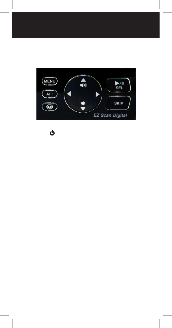
Understanding the Keypad
Your WS1095 features a simplied backlit keypad with
9 keys as shown below in addition to the power button
located at the front of the remote control head.
POWER/Backlight
The POWER key is located to the bottom right of
the remote head. Press and hold for one second to
turn the WS1095 on and o. Press briey to conrm
the backlight level. When the backlight level appears,
rotate rotary encoder to increase/ decrease the
backlight level.
MENU Key
The MENU key provides access to additional
functions related to the current operating mode of
the scanner, and provides access to the Main Menu,
where the main WS1095 functions are controlled.
SKIP Key
When pressed while the WS1095 is monitoring or
paused on an Object, the SKIP key will temporarily
disable reception on the Object. Pressing SKIP again
while the Object is selected will resume normal
monitoring. Skipped Objects can also be restored
using the Restored Skipped option from the Main
Menu. The SKIP key can also be programmed to
permanently lockout an object if selected in the
settings menu. When editing text, pressing the SKIP
key clears all text at and to the right of the cursor.
When in Playback mode, the SKIP key stops playback
of the current recording, and when playing multiple
recordings, advances to the next recording.
14

KEYPAD
When in Weather mode, the SKIP key toggles between
Normal weather radio mode and SAME Standby mode.
In many Menu functions, the SKIP key is used to cancel
or abort a pending change.
SCAN/PAUSE/SELECT Key
The SCAN/PAUSE/SELECT key /II/SEL controls WS1095’s
Scan, Pause and Playback modes, and is used in menus to
select, enable or disable options.
UP Arrow Key
The UP Arrow key is used to increase the volume when
the WS1095 is scanning or monitoring Objects. When
browsing Objects, the key scrolls up through Objects
in a Scanlist. When using menus, recordings or the
Library, the scrolls up through the available items.
DOWN Arrow Key
The DOWN Arrow key is used to decrease the
volume when the WS1095 is scanning or monitoring
Objects. When browsing Objects, the key scrolls
down through Objects in a Scanlist. When using
menus, recordings or the Library, the scrolls down
through the available items.
RIGHT Arrow Key
The RIGHT Arrow key is used to resume scanning
when the WS1095 is scanning or monitoring Objects
and is stopped on an active Object while scanning
without locking out or skipping the Object. When
browsing Objects, the key scrolls up through the
Scanlists. When using menus or the Library, the
navigates forward, or in, to the next menu or Library
listing or level. In Playback mode, the key advances
ve seconds forward in the recorded le being played.
LEFT Arrow Key
The LEFT Arrow key is used to resume scanning when
the WS1095 is scanning or monitoring Objects and is
stopped on an active Object while scanning without
locking out or skipping the Object. When browsing
Objects, the key scrolls down through the Scanlists.
When using menus or the Library, the navigates
backward, or out, to the previous menu or Library
listing or level. In Playback mode, the key moves ve
seconds back in the recorded le being played.
15

ROTARY ENCODER
ATT Key
The Attenuator ATT key provides front panel control
of the radio’s attenuator function. Pressing the ATT key
cycles between per object attenuation mode, Global
attenuation mode, and Global attenuation on.
SKY Key
When pressed, the SKY key provides instant access to
NOAA Weather Radio broadcasts, and is used to access
Dedicated SAME Weather Alert Receiver mode, which
allows the WS1095 to remain silent while monitoring
for severe weather conditions in the area you specify
by entering NOAA SAME codes. Pressing the SKY
key a second time selects the SKYWARN Scanlist for
monitoring and temporarily disables all other Scanlists.
Skywarn requires one - time programming.
Rotary Encoder
The WS1095 is equipped with a multi-function control
knob, mounted on the top-right of the remote head.
You can turn the knob right and left, and press it to click.
The rotary encoder functions are “context sensitive”.
You can select the desired rotary encoder operating
mode (volume or squelch) in the Settings menu under
Knob Dt. Set the desired rotary encoder timeout time
in seconds in the Settings menu under Knob T/Out.
Factory default function is volume control during
scanning. Pressing the knob once temporarily changes
to squelch control. After 5 seconds (settable) of
inactivity the knob reverts to its default function.
In squelch mode the default function is to scroll
through squelch levels while scanning. Pressing the
knob once temporarily changes to volume control. After
5 seconds (settable) of inactivity the knob reverts to its
default function.
16

ROTARY ENCODER
Use the squelch function to optimize reception. When
the squelch level is high, only stronger signals will pass
through the squelch gate, and weaker signals may not
be received. When the squelch level is low, the squelch
gate will be open even when no signal is present, causing
WS1095 to scan slowly or to stop on Objects even when
no transmission is present, playing noise only. The WS1095
works best when the squelch gate is set so that it is closed
when no transmissions are present, but able to open when
a desired transmission occurs. The ideal setting for the
squelch level is between 9 and 11.
If you nd that the WS1095 seems to be scanning very
slowly or stopping on frequencies with noise only, increase
the squelch level until normal scanning resumes.
In menus, the rotary encoder scrolls up and down through
the menu items and a single press selects the indicated
menu option. When entering alphanumeric data such as
Scan List names the rotary encoder scrolls up and down
the character list (letters, numbers, punctuation); a single
press selects the indicated character.
The rotary encoder can be used to adjust the backlight
level. Press POWER briey with backlight illuminated, then
rotate the encoder to increase or decrease brightness.
17

DISPLAY
Understanding the Display
Your WS1095 features a high contrast, backlit Liquid
Crystal Display (LCD) to provide you with information
about the status of the WS1095 while you are using
it. A menu-driven user interface provides access to
the settings that control what the WS1095 monitors.
Figure 3 shows an example of an WS1095 menu.
-Main MenuScan
Scanlists
Set Location
Browse Library
Browse Objects
Figure 3 - WS1095 Main Menu
A “Scan” display shows a scrolling list of enabled
Scanlists while the WS1095 is scanning, and displays
attenuator and trunking control channel status. Figure 4
provides an example of the WS1095’s Scanning display.
Scan T G
Fire
County Police
Sheriff
City Police
State Police
Figure 4 - WS1095 Scanning Display
Individual Object displays are shown when the
scanner is monitoring activity on an enabled
Object. The LCD includes a row of icons at the top
that provides information about the status of the
WS1095 while monitoring an Object. The amount of
information displayed is congured using the Simple
Display option in the Settings menu. For example,
with Simple Display set to “on”, the following data is
displayed for trunking talkgroups:
• Icons
• Scanlist
• Object type and “psDr” status
• Trunking system
• Scanlist
18

DISPLAY
Figure 5 provides an example of an individual Object
display with Simple Display set to “on”.
S
T G
County Police
Group: psDR
Police North
Figure 5 - WS1095 Channel Object
Display showing reception of a trunking talkgroup
with Simple Display set to “on”. With Simple Display set
to “o”, additional data is displayed on the screen. The
amount and type of data displayed can be customized
using the Show options in the Settings menu. For
example, Figure 6 shows the same Object displayed
with Simple Display set to “o” and Show Radio ID set
to “on”:
• Icons
• Scanlist
• Object type and “psDr” status
• Object name
• Trunking system
• Radio ID
Figure 6 - WS1095 Channel Object
Public Safety
G
S
County Police
TGRP psDR
Police North
Public Safety
Radio ID: 18249
T
Display showing reception of a trunking talkgroup with
Simple Display set to “on” and Show Radio ID enabled.
There are many combinations of data that can be
shown on the Object display using the Show options
in the Settings menu. You can learn more about these
options in the Settings Menu section of the manual.
19

DISPLAY ICONS
“psDr” Indicators
In the Individual Object displays there are four
characters on the right hand side of the display that
indicate the status of priority, skip/lockout, delay
and recording for the selected or active object. The
following indicators are possible:
p= priority o, P= priority on
s= skip o, S= skip on, L= lockout on
d= delay o, D= delay on
r= recording o, R= recording on
Display Icons
In the Individual Object displays, a row of icons at the
top of the display provides status information about the
scanner. The top row of icons are dened as follows:
WS1095’s squelch circuit (or “gate”) is open
S
When present, the attenuator is set for Global mode
G
When present, the attenuator is active
A
When present, Global attenuator is on, and the
GA
attenuator is active
AM mode is active
AM
FM mode is active
FM
Narrow FM mode is active
NF
The radio is receiving P25 digital audio with AGC
DG
The radio is receiving P25 digital audio without AGC
Dg
The radio is receiving P25 Phase II digital audio, with
D2
or without AGC
20

DISPLAY ICONS
WS1095 is in Scan mode (scanning)
WS1095 is in Pause mode (monitoring a single Object)
Audio is being recorded on the active or selected
Object
Audio recording is enabled but recording is suspended.
The SD card is almost out of space. Delete or archive
F
older audio les to make room for new recordings.
Signal meter indicating strength of the received
signal
The scanner is currently receiving trunking
control channel data, or, when monitoring a
voice channel, ashes to indicate reception of
T
embedded low-speed trunking data from the
voice channel
Encrypted digital trac detected
E
21
 Loading...