

The Whistler Group BU01C, BU01M User Manual
WBU-900
User Guide
Product Marketing Name: Camera
Hardware Version Identification Number: WBU-900C
Product Marketing Name: Monitor
Hardware Version Identification Number: WBU-900M
B
ACK-UP CAMERA
INSTALLS IN MINUTES

INTRODUCTION
Welcome
Thank you for choosing a Whistler product. We are dedicated
to providing products that represent both quality and value.
Please read the User Guide carefully before using this product.
If you have additional questions, please visit the FAQ page on
our website at
www.whistlergroup.com
or call Toll Free (800) 531-0004 / Tel (479) 273-6012,
8am to 5pm CT, Monday through Friday
to speak to a Customer Service Representative.
The Back-Up Camera displays images behind the vehicle, and
can be used when backing up or anytime you need to view
behind the vehicle even when the vehicle is in park.
2

FEATURES
Features
• 4.3" Color monitor with backlit capacitive touch buttons
• Weatherproof camera with 110° viewing angle
• Solar Cells for extended battery life
• Modular design can be placed above or below your license
plate
• Adjustable vertical camera tilt angle
• Suction Cup with adjustable arm for windshield or
dashboard mounting
• Dash Disk provides smooth surface for suction cup to be
dash mounted
• Back-up assist guidelines
• Image Rotation / Mirroring
3
1
5 6
7
10
9
FEATURES
2 3 4
8
17
11
18
12 13 14 15 16
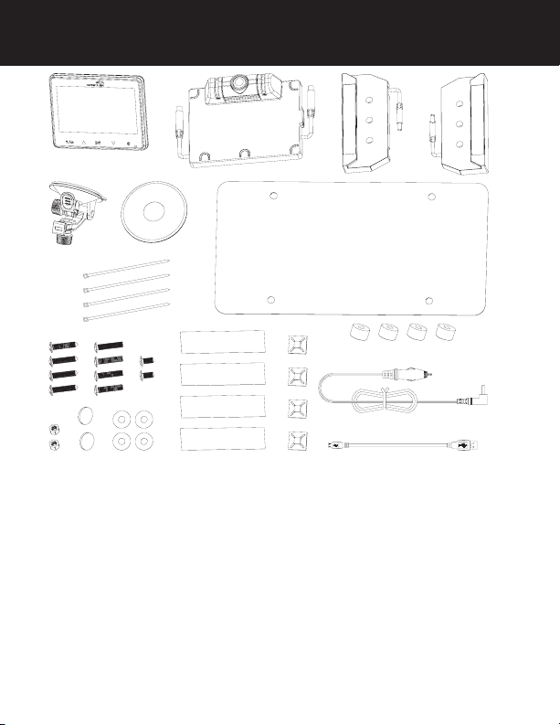
1. Monitor
2. Camera
3. Solar cell
4. Solar cell
5. Suction cup mount
6. Dash disk
7. Tie wraps
8. License back-plate
9. 4 Long screws (Domestic)
10. 4 Long screws (Import)
4
19
11. 2 Short Machine screws
12. 2 Machine nuts
13. 2 Cushions
14. 4 Adhesive disks
15. 4 Adhesive strips
16. 4 Cable tie mount
17. 4 Spacers
18. Power cord
19. USB cord

CHARGING CAMERA ASSEMBLY
The Camera under normal use, will maintain a charge with
exposure to sunlight. A battery status indicator is provided
on the monitor when the camera is in use. If you’re storing
your vehicle in a garage for more than a one month, or are
otherwise not exposing the Camera to sunlight on a regular
basis, you may need to recharge it via the Micro USB charge
port.
To recharge the Camera:
1. If attached to vehicle, please remove.
2. Connect the supplied USB cord to the Micro USB port of
the camera assembly.
3. Plug the USB cable into any standard USB charger with an
output rating of 500ma or higher.
4. Charge 4 to 5 hours if the battery was completely depleted
5. Once charged, Re-install the Camera assembly to your
vehicle.
NOTE: It is recommended to fully charge your Camera before
installing on the vehicle.
Tips to optimize the solar charge:
1. Be sure that the solar panels are are clean, and dust/dirtfree.
2. Park in a location where the sun is or will be shining directly
on the solar panels for at least 1-2 hours a day.
3. One hour of good sunlight daily offsets the daily power
consumption of the Camera.
5
ASSEMBLY / INSTALLATION
Notice
Some states or local governments may have regulations or
laws that restrict the use of anything that might impair the
clear view of a license plate. Check local laws for compliance
These instructions are only meant as a general guide due to
the number of different makes and models of vehicles.
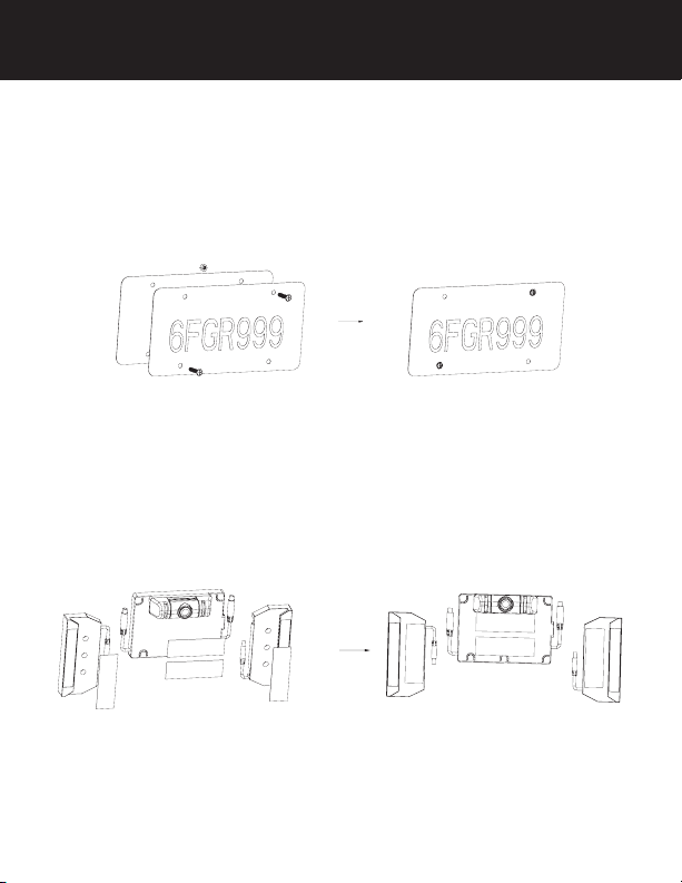
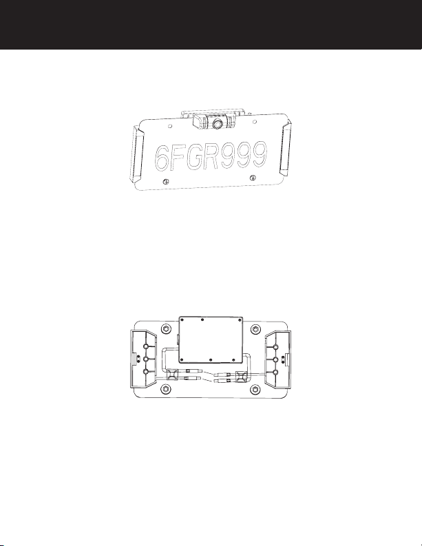
1. Remove license plate from vehicle and place on top of
the supplied license backplate.
2. Insert 2 short machine screws into 2 of the mounting holes
and finger tighten 2 machine nuts onto them in order to
hold the plates together for steps 3 thru 6.
3. Apply an adhesive strip to each of the solar panel bases
and two adhesive strips to the camera base as shown
below.
4. Peel the backing from the adhesive strips on the solar
panel bases and carefully slide onto each side (left and
right) of the plate assembly being careful not to make
contact with the adhesive until the base is fully inserted.
6
ASSEMBLY / INSTALLATION
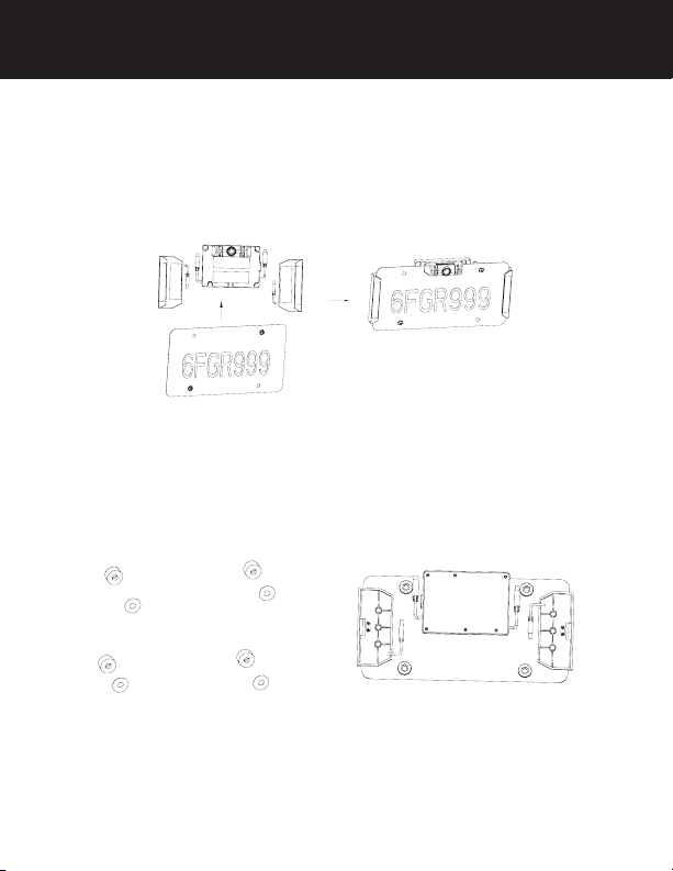
5. With the solar mounts centrally positioned, apply pressure
to set the adhesive tape.
6. Peel the backing from the adhesive strips on the camera
base and carefully slide onto the long edge of the license
plate assembly positioned centrally between the license
plate mounting holes.
7. Remove the 2 short machine screws and nuts used earlier
and set aside.
8. Apply the 4 adhesive disks to the flat side on each of the
4 spacers.
9. Peel the backing from the adhesive disks and apply one
spacer over each license plate mounting holes.
10. Apply pressure to set the adhesive tape.
7
ASSEMBLY / INSTALLATION
11. Reinsert the 2 short machine screws into the 2 holes if
these are not used to attach to your vehicle, insert the
machine nuts, then tighten.
12. If needed, 2 cushions are provided to protect your
vehicle. Attach to the back of the spacers containing the
machine nuts.
13. Connect the solar panel connectors to the mating
connectors from the main camera housing and place
the tie wrap adhesive pads as shown. Use 2 tie wraps to
neatly hold the cables in place and cut the excess length
of the tie wrap if desired.
14. Attach the assembly to the vehicle with the appropriate
license plate mounting screws for your vehicle type.
NOTE: Domestic and Import license plate screws are included
and should be compatible with the vast majority of vehicles.
Should your vehicle require a special diameter or thread,
please consult your dealer.
8

ASSEMBLY / INSTALLATION
The camera angle should be adjusted to provide an optimal
view of objects behind the vehicle.
15. Adjust the camera angle as required:
• To adjust the camera angle, tilt the camera to the correct
angle.
• The camera should be adjusted to a horizontal position
relative to the ground, so as to provide optimal view of
objects behind the vehicle.
• Carefully tighten the 2 screws ½ turn to prevent the
camera angle from moving during vibrations from driving.
16. Find a mounting surface inside the vehicle for the monitor
where it can be easily seen, and does not obstruct your
vision when driving.
NOTE: To maximize the effectiveness of the suction mount,
the mounting location surface temperature should be between
50° and 100°F. Avoid application below 50°F.
NOTE: Before permanently mounting the monitor, test the
reception of the camera signal in several selected locations
within easy reach as one may have better reception than
another. If mounting to the dashboard, the dash disk must
be used to ensure a smooth surface for the suction cup to
attach.
9
 Loading...