

Page 1

DSP 204, DSP 206, DSP 306, DSP 408
Digital speaker management system
user manual
Page 2

Musikhaus Thomann
Thomann GmbH
Hans-Thomann-Straße 1
96138 Burgebrach
Germany
Telephone: +49 (0) 9546 9223-0
E-mail: [email protected]
Internet: www.thomann.de
14.06.2018, ID: 435191, 435192, 435193, 435194
Page 3

Table of contents
1 General information.............................................................................................................. 4
1.1 Further information........................................................................................................ 4
1.2 Notational conventions................................................................................................. 4
1.3 Symbols and signal words........................................................................................... 5
2 Safety instructions................................................................................................................. 6
3 Features....................................................................................................................................... 7
4 Installation and starting up............................................................................................... 8
5 Connections and controls................................................................................................ 10
6 Operating on the unit........................................................................................................ 12
7 Control on the computer.................................................................................................. 18
8 Technical specifications.................................................................................................... 29
9 Plug and connection assignment................................................................................. 30
10 Protecting the environment........................................................................................... 31
Table of contents
DSP 204, DSP 206, DSP 306, DSP 408
3
Page 4

1 General information
This manual contains important instructions for the safe operation of the unit. Read
and follow the safety instructions and all other instructions. Keep the manual for
future reference. Make sure that it is available to all those using the device. If you sell
the unit please make sure that the buyer also receives this manual.
Our products are subject to a process of continuous development. Thus, they are
subject to change.
1.1 Further information
On our website (www.thomann.de) you will find lots of further information and
details on the following points:
Download This manual is also available as PDF file for you to download.
Keyword search
Use the search function in the electronic version to find the
topics of interest for you quickly.
Online guides
Our online guides provide detailed information on technical
basics and terms.
Personal
consultation
For personal consultation please contact our
technical hotline.
Service
If you have any problems with the device the
customer service will gladly assist you.
1.2 Notational conventions
This manual uses the following notational conventions:
The letterings for connectors and controls are marked by square brackets and italics.
Examples: [VOLUME] control, [Mono] button.
Texts and values displayed on the device are marked by quotation marks and italics.
Examples: ‘24ch’, ‘OFF’.
Text inputs that are carried out on the device are indicated by typewriter font.
Example:
2323
Letterings
Displays
Text input
General information
Digital speaker management system
4
Page 5

The individual steps of an instruction are numbered consecutively. The result of a
step is indented and highlighted by an arrow.
Example:
1. Switch on the device.
2. Press [Auto].
ð
Automatic operation is started.
3. Switch off the device.
1.3 Symbols and signal words
In this section you will find an overview of the meaning of symbols and signal words
that are used in this manual.
Signal word Meaning
DANGER! This combination of symbol and signal word indicates
an immediate dangerous situation that will result in
death or serious injury if it is not avoided.
NOTICE! This combination of symbol and signal word indicates
a possible dangerous situation that can result in material and environmental damage if it is not avoided.
Warning signs Type of danger
Warning – danger zone.
Instructions
General information
DSP 204, DSP 206, DSP 306, DSP 408
5
Page 6

2 Safety instructions
This device is intended to be used for amplification, mixing and playback of signals
from musical instruments and microphones. Use the device only as described in this
user manual. Any other use or use under other operating conditions is considered to
be improper and may result in personal injury or property damage. No liability will be
assumed for damages resulting from improper use.
This device may be used only by persons with sufficient physical, sensorial, and intellectual abilities and having corresponding knowledge and experience. Other persons
may use this device only if they are supervised or instructed by a person who is
responsible for their safety.
DANGER!
Danger for children
Ensure that plastic bags, packaging, etc. are disposed of properly and
are not within reach of babies and young children. Choking hazard!
Ensure that children do not detach any small parts (e.g. knobs or the
like) from the unit. They could swallow the pieces and choke!
Never let children unattended use electrical devices.
NOTICE!
Risk of fire
Do not block areas of ventilation. Do not install the device near any
direct heat source. Keep the device away from naked flames.
NOTICE!
Operating conditions
This device has been designed for indoor use only. To prevent damage,
never expose the device to any liquid or moisture. Avoid direct sunlight,
heavy dirt, and strong vibrations.
Intended use
Safety
Safety instructions
Digital speaker management system
6
Page 7

3 Features
n Digital mixer
n
Inputs:
– DSP 204 (item no. 435191): 2 mono channels (XLR chassis sockets) for signals
with line level
– DSP 206 (item no. 435192): 2 mono channels (XLR chassis sockets) for signals
with line level
– DSP 306 (item no. 435193): 3 mono channels (XLR chassis sockets) for signals
with line level
– DSP 408 (item no. 435194): 4 mono channels (XLR chassis sockets) for signals
with line level
n
Outputs:
– DSP 204 (item no. 435191): 4 mono channels (XLR chassis plugs) for signals
with line level
– DSP 206 (item no. 435192): 6 mono channels (XLR chassis plugs) for signals
with line level
– DSP 306 (item no. 435193): 6 mono channels (XLR chassis plugs) for signals
with line level
– DSP 408 (item no. 435194): 8 mono channels (XLR chassis plugs) for signals
with line level
n
Comprehensive setting options for optimal sound:
– Parametric equalizer
– Graphic equalizer
– High- and low-pass filters
– Noise Gate
– Limiter
– Phase inversion
n
USB port for computer control using the supplied software
n
D-Sub socket for remote control or for the cascading of several devices
n
Network connection for integrating the device in a local network
n
Operation of the device via buttons, jog wheel and display
Features
DSP 204, DSP 206, DSP 306, DSP 408
7
Page 8

4 Installation and starting up
Unpack and carefully check that there is no transportation damage before using the
unit. Keep the equipment packaging. To fully protect the device against vibration,
dust and moisture during transportation or storage use the original packaging or
your own packaging material suitable for transport or storage, respectively.
Create all connections while the device is off. Use the shortest possible high-quality
cables for all connections. Take care when running the cables to prevent tripping
hazards.
The unit has been designed for rack mounting in a standard 19-inch rack; it occupies
one rack unit.
The figure schematically shows how the device can be controlled via a computer's
USB port.
Rack mounting
Configuration example 1
Installation and starting up
Digital speaker management system
8
Page 9

The figure schematically shows how one or more devices can be integrated into a
local network (LAN).
The figure schematically shows how one or more devices can be connected in a row
via the serial interface (cascading).
Configuration example 2
Configuration example 3
Installation and starting up
DSP 204, DSP 206, DSP 306, DSP 408
9
Page 10

5 Connections and controls
1 [INPUTS]
Level indicator for the input channels. The number of channels depends on the device design.
The red [CLIP] LEDs indicate overload (clipping). In this case the level of the input signal is too high.
2 [EDIT]
Buttons for selecting the edit mode for the respective input channel. The set parameters of the selected channel
appear in the display.
3 [MUTE]
Buttons for muting or unmuting the respective input channel.
4 [OUTPUTS]
Level indicator for the output channels. The number of channels depends on the device design.
The red [CLIP] LEDs indicate overload (clipping). In this case the level of the output signal is too high. The red [LIMIT]
LEDs indicate that the built-in limiter has been tripped.
5 [EDIT]
Buttons for selecting the edit mode for the respective output channel. The set parameters of the selected channel
appear in the display.
6 [MUTE]
Buttons for muting or unmuting the respective output channel.
7 Display
8 [ENTER / PARAMETER]
Jog wheel
9 Buttons for direct selection of a parameter. Use the [EXIT] button to leave the edit mode.
10 [USB]
USB port
Front panel
Connections and controls
Digital speaker management system
10
Page 11

11 Plug for mains cable with fuse holder
12 [POWER]
Main switch. Turns the device on and off
13 [ETHERNET]
RJ45 socket as a LAN port to connect with your network
14 [RS232/485PORT]
D-Sub socket for remote control or for the cascading of several devices
15 [OUTPUTS]
XLR chassis plugs for the output channels. The number of channels depends on the device design.
16 [INPUTS]
XLR chassis sockets for the output channels. The number of channels depends on the device design.
Rear panel
Connections and controls
DSP 204, DSP 206, DSP 306, DSP 408
11
Page 12

6 Operating on the unit
Connect the device to the power grid and turn it on with the main switch to start
operation. After a few seconds, the display indicates that a reset is in progress. The
device is then ready for use. The display shows the model name and the user preset
that's currently active.
The device can only be operated directly with the buttons if it is not being controlled
via USB, LAN or the serial interface.
The buttons that can currently be used light up continuously, and the most previously used ones flash on and off. Buttons that cannot be used at the moment
remains dark.
1. Keep pressing [UTIL] until the parameter you want appears in the display.
The table below shows the available parameters and their ranges.
2. Use the jog wheel to set the desired value of the parameter. Press the jog
wheel to confirm.
3. Press [EXIT].
Parameter Selection range Meaning
‘ID Number Select’ ‘1’ …‘254’ Unique identification of the device when connected serially (in
a cascade configuration). If several devices are connected serially, each of them must have a unique ID number.
‘Manual IP Set’ If the device is connected to a local network, its IP address can
be set individually. The initial IP address is
192.168.1.101
.
‘Unit Lock PassWord’ ‘0000’ …‘ZZZZ’ Four-character device password. Any combination of letters or
numbers can be set. The initial password is
1234
.
‘Input Source Select’ ‘ANALOG INPUT’ , ‘PINK NOISE’ ,
‘WHITE NOISE’ , ‘SINE xx’
Selection of the signal source: Either the analogue inputs or
the internal test tone generator. The test tone generator can
produce either: pink noise, white noise or a sine wave of
20 Hz…20 kHz.
‘Copy CH select’ Copies the settings from one channel to another.
‘Delay Units Select’ ‘ms’ , ‘m’ , ‘ft’ Selects the unit for displaying the delay: Milliseconds, metres
or feet.
Starting the device
Default settings
Operating on the unit
Digital speaker management system
12
Page 13

All device settings can be saved in up to 20 different user presets and then recalled as
needed. That way you can easily restore your settings for different rooms or stage
set-ups.
1. Press [SAVE].
ð
The ‘Store Preset’ menu opens.
2. Use the jog wheel to select a user preset between ‘U01’ and ‘U20’. Press the
jog wheel to confirm.
3. Using the jog wheel, enter the name of the user preset by changing the
Default Preset
standard value.
ð
The settings are saved.
4. Press [EXIT].
1. Press [RECALL].
ð
The ‘Load preset’ menu opens.
2. Use the jog wheel to select a user preset between ‘U01’ and ‘U20’ or the basic
setting ‘F00’. Press the jog wheel to confirm.
ð
The settings are loaded.
User presets
Save use preset
Call up user preset
Operating on the unit
DSP 204, DSP 206, DSP 306, DSP 408
13
Page 14

1. Press the [EDIT] button assigned to the desired channel.
ð
The settings menu for the desired channel will open. The display shows
‘GAIN’ .
2. In the basic state of the menu, you can set the level of the channel within a
range of –60 dB…+12 dB using the jog wheel.
3. Press the respective button to set further parameters for the channel.
Use the jog wheel to set the desired value of the parameter. Press the jog
wheel to confirm.
The table below shows the available parameters and their ranges.
Parameter
Button Selection range Meaning
‘PEQ’ 1 ×
[PEQ/GEQ]
‘PEQ’ : ‘1’ …‘9’
‘F’ : ‘20Hz’ …‘20kHz’
‘Q’ : ‘0.4’ …‘128’
‘G’ : ‘-12dB’ …‘+12dB’
‘Style’ : ‘PEAK’ , ‘L-SHLF’ , ‘H-SHLF’, ‘LP6dB’,
‘LP12dB’ , ‘HP6dB’ , ‘HP12dB’ , ‘A-PAS1’, ‘A-PAS2’
‘ON’ , ‘BP’
For 9 frequency bands (numbered with the
parameter ‘PEQ’), the parameters of the parametric equalizer can be set individually: Centre
frequency, filter quality, slope, filter type, bypass
‘GEQ’ 2 ×
[PEQ/GEQ]
‘Freq’ : ‘20Hz’ …‘20kHz’
‘Gain’ : ‘-12dB’ …‘+12dB’
Graphic equalizer parameters: The frequency
range is divided into 31 fixed preset areas (numbered with the parameter ‘GEQ’), which can be
set separately for boost or cut.
‘INLINK’ [LINK] The settings of several input channels can be
linked to each other. The number of input channels depends on the device design.
‘DELAY’ [DELAY] ‘0ms’ … ‘680ms’
‘0m’ …‘234m’
‘0ft’ …‘766ft’
Delay time. The units that are displayed depends
on the device's default setting.
‘X-OVER’ [X-OVER] ‘HP’ : ‘20Hz’… ‘20kHz’
‘LP’ : ‘20Hz’ …‘20kHz’
‘BUTTER-xx’ (Butterworth), ‘BESSEL-xx’ (Bessel),
‘LINK/R-xx’ (Linkwitz-Riley), ‘BYPASS’ (Filter
switched off)
Parameters for digital high pass and low pass:
Cut-off frequency, slope and filter type
Input settings
Operating on the unit
Digital speaker management system
14
Page 15

Parameter
Button Selection range Meaning
‘GATE’ [COMP/
GATE]
‘T’ : ‘-90dB’ …‘-0dB’
‘HT’ : ‘10’ …‘999’ (in milliseconds)
‘AT’ : ‘1ms’ …‘999ms’
‘RT’ : ‘10ms’ …‘3000ms’
Parameters for the noise gate: Threshold, hold,
attack, release
‘PHASE’ [PHASE] ‘0’ , ‘180’ Inversion of phase length
Operating on the unit
DSP 204, DSP 206, DSP 306, DSP 408
15
Page 16

1. Press the [EDIT] button assigned to the desired channel.
ð
The settings menu for the desired channel will open. The display shows
‘GAIN’ .
2. In the basic state of the menu, you can set the level of the channel within a
range of –60 dB…+12 dB using the jog wheel.
3. Press the respective button to set further parameters for the channel.
Use the jog wheel to set the desired value of the parameter. Press the jog
wheel to confirm.
The table below shows the available parameters and their ranges.
Parameter
Button Selection range Meaning
‘PEQ’ 1 ×
[PEQ/GEQ]
‘PEQ’ : ‘1’ …‘9’
‘F’ : ‘20Hz’ …‘20kHz’
‘Q’ : ‘0.4’ …‘128’
‘G’ : ‘-12dB’ …‘+12dB’
‘Style’ : ‘PEAK’ , ‘L-SHLF’ , ‘H-SHLF’, ‘LP6dB’,
‘LP12dB’ , ‘HP6dB’ , ‘HP12dB’ , ‘A-PAS1’, ‘A-PAS2’
‘ON’ , ‘BP’
For 9 frequency bands (numbered with the
parameter ‘PEQ’), the parameters of the parametric equalizer can be set individually: Centre
frequency, filter quality, slope, filter type, bypass
‘INLINK’ [LINK] The settings of several output channels can be
linked to each other. The number of output channels depends on the device design.
‘DELAY’ [DELAY] ‘0ms’ … ‘680ms’
‘0m’ …‘234m’
‘0ft’ …‘766ft’
Delay time. The units that are displayed depends
on the device's default setting.
‘X-OVER’ [X-OVER] ‘HP’ : ‘20Hz’… ‘20kHz’
‘LP’ : ‘20Hz’ …‘20kHz’
‘BUTTER-xx’ (Butterworth), ‘BESSEL-xx’ (Bessel),
‘LINK/R-xx’ (Linkwitz-Riley), ‘BYPASS’ (Filter
switched off)
Parameters for digital high pass and low pass:
Cut-off frequency, slope and filter type
‘MATRIX’ 1 ×
‘MATRIX’
Selection of the assignment of the input channels
to the respective output channel. Each output
channel can be freely assigned to one input
channel or a mix of several input channels. The
selected input channels are marked with ‘X’.
‘MATRIX
Output’
2 ×
‘MATRIX’
‘-60dB’ …‘+0dB’ One level adjustment can be set for each of the
input channels assigned to the respective output
channel.
Output settings
Operating on the unit
Digital speaker management system
16
Page 17

Parameter
Button Selection range Meaning
‘GATE’ 1 ×
[COMP/
GATE]
‘T’ : ‘-90dB’ …‘-0dB’
‘HT’ : ‘10ms’ …‘999ms’
‘AT’ : ‘1ms’ …‘999ms’
‘RT’ : ‘10ms’ …‘3000ms’
Parameters for the noise gate: Threshold, hold,
attack, release
‘LIMIT’ 2 ×
[COMP/
GATE]
‘TH’ : ‘-90dB’ …‘+20dB’
‘AT’ : ‘1ms’ …‘999ms’
‘RT’ : ‘10ms’ …‘3000ms’
Parameters for the limiter: Threshold, attack,
release
‘PHASE’ [PHASE] ‘0’ , ‘180’ Inversion of phase length
Operating on the unit
DSP 204, DSP 206, DSP 306, DSP 408
17
Page 18

7 Control on the computer
1. Place the CD with the software into the CD drive of a computer with a Win-
dows operating system and start the installation programme that matches the
device you have.
2. Follow the instructions of the installation programme until it is finished.
3. Connect your computer via a USB cable to the device and switch the device on.
ð
The operating system recognizes the newly added USB device.
4. Open the computer programme. It automatically recognized the attached
device.
ð
The ‘Online’ marking will appear in the upper right corner of the programme window.
1. Click on the ‘Online’ button in the programme window.
2. Close the programme window.
Installing and starting the software
Closing the software
Control on the computer
Digital speaker management system
18
Page 19

All of the programme window tabs have a similar design and are grouped into the
following areas:
1 Tabs for selecting a function group
2 Main menu
3 Button for the status of the connection to the computer
4 Display area
5 Control area
6 Buttons for quick access to the important presets
Menu item Meaning
‘File’ Load user presets and save them on the computer
‘Link’ Assign input and output channels
‘Copy’ Copy parameter settings from one input or output channel to another
‘Lock’ Change device password
‘Setting ID/IP’ Change unique ID of the device in a serial configuration or IP address for integrating into a local net-
work
‘Test tone’ Setting of the internal test tone generator: Pink noise, white noise, sine wave 20 Hz…20 kHz.
‘Channel name’ Rename the input and output channels
‘Language’ Language selection for the programme user interface (English or Chinese)
‘Help’ Display of the control code for the serial interface
‘About’ Information about the programme version
Parts of the programme window
Main menu
Control on the computer
DSP 204, DSP 206, DSP 306, DSP 408
19
Page 20
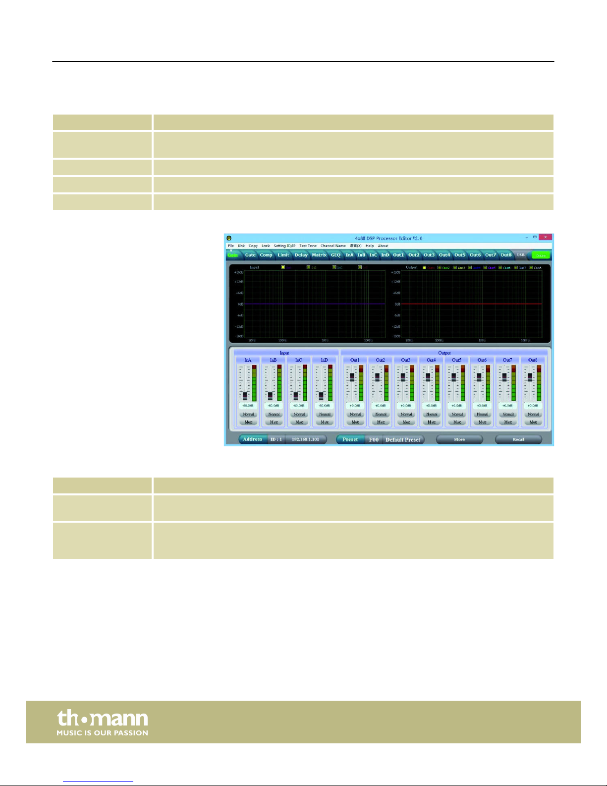
Range Meaning
Address Display of the ID of the device in a serial configuration or IP address for integrating into a local net-
work
Preset Display of the current user preset
Store Save user preset
Recall Call up user preset
Range Meaning
Display area The signal curve of the input and output channels is displayed graphically. Use the ‘Inx’ and ‘Outx’
option fields to set the inputs and outputs that should be displayed.
Control area Drag the fader with the mouse to set the limits for the input and output channels: The ‘Mute’ button
mutes or unmutes the respective channel. The ‘Normal’/ ‘Inverse’ button inverts the phase of the
respective channel by 180° if needed.
Buttons for quick access to the important presets
“Gain” tab
Control on the computer
Digital speaker management system
20
Page 21

Range Meaning
Display area Shows the current settings of the noise gate for the respective channel, with a symbolic level indi-
cator symbol appearing next to it for the input channels. The red dot on the curve represents the cur-
rent signal.
Control area Drag the fader with the mouse to set the noise gate parameters for all input and output channels:
Threshold, hold, attack, release
“Gate” tab
Control on the computer
DSP 204, DSP 206, DSP 306, DSP 408
21
Page 22
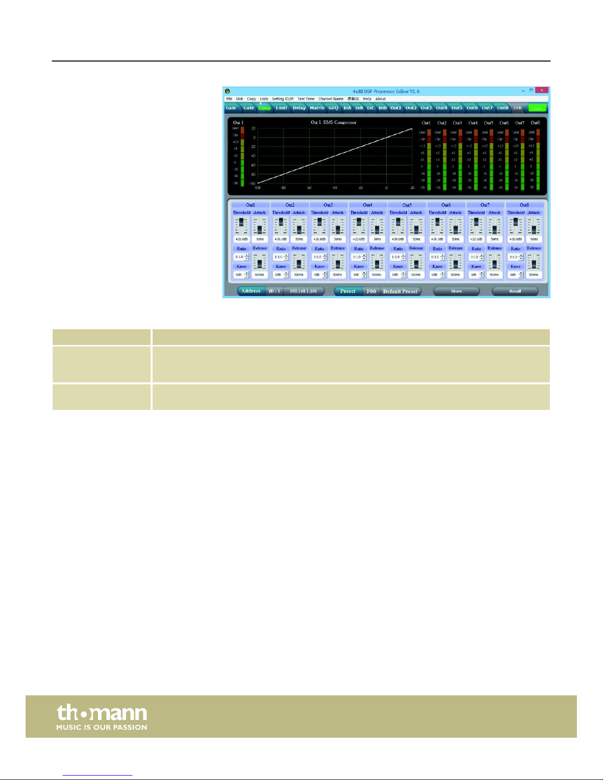
Range Meaning
Display area Shows the current settings of the compressor function for the respective output channel, with a sym-
bolic level indicator symbol appearing next to it for the input channels. The red dot on the curve rep-
resents the current signal.
Control area Drag the fader with the mouse to set the compressor function parameters for all output channels:
Compression, threshold, ratio, attack, release
“Comp” tab
Control on the computer
Digital speaker management system
22
Page 23
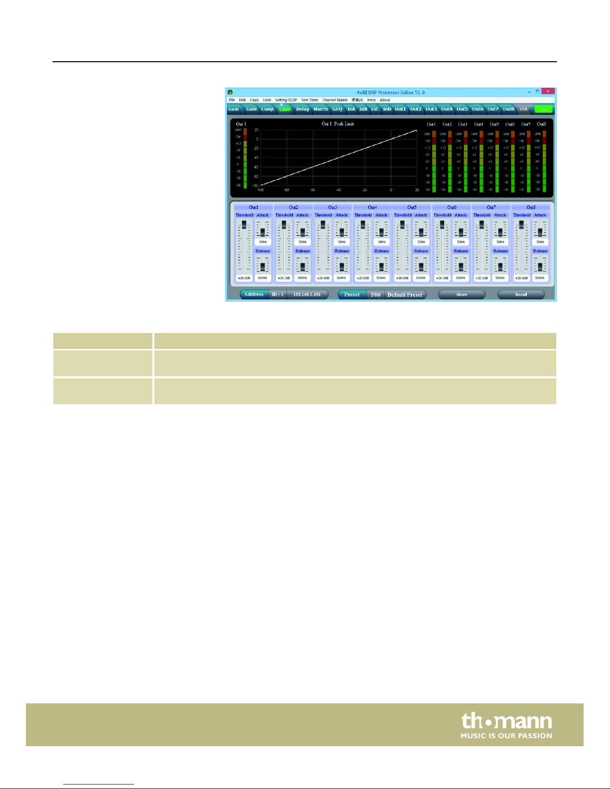
Range Meaning
Display area Shows the current settings of the limiter for the respective channel, with a symbolic level indicator
symbol appearing next to it for all channels.
Control area Drag the fader with the mouse to set the limiter parameters for all input and output channels:
Threshold, attack, release
“Limit” tab
Control on the computer
DSP 204, DSP 206, DSP 306, DSP 408
23
Page 24

Range Meaning
Display area Shows the set delays for all input and output channels.
Control area Drag the fader with the mouse to set the delay for the respective channel. Press one of the buttons
‘ms’ , ‘m’ or ‘ft’ to select the unit to use.
“Delay” tab
Control on the computer
Digital speaker management system
24
Page 25

Range Meaning
Display area Shows the current configuration of input to output channels.
Output and input channels can be renamed. Click on a function area (e.g. ‘GEQ’ or ‘DELAY’) to open
the tab in which you can directly enter the corresponding parameters.
Control area By clicking with the mouse you can connect any input channel to any output channel. Each output
channel can be freely assigned to one input channel or a mix of several input channels. The input
channels with a green background are assigned to the respective output channel. You can set a level
adjustment for any combination of input and output channel.
“Matrix” tab
Control on the computer
DSP 204, DSP 206, DSP 306, DSP 408
25
Page 26
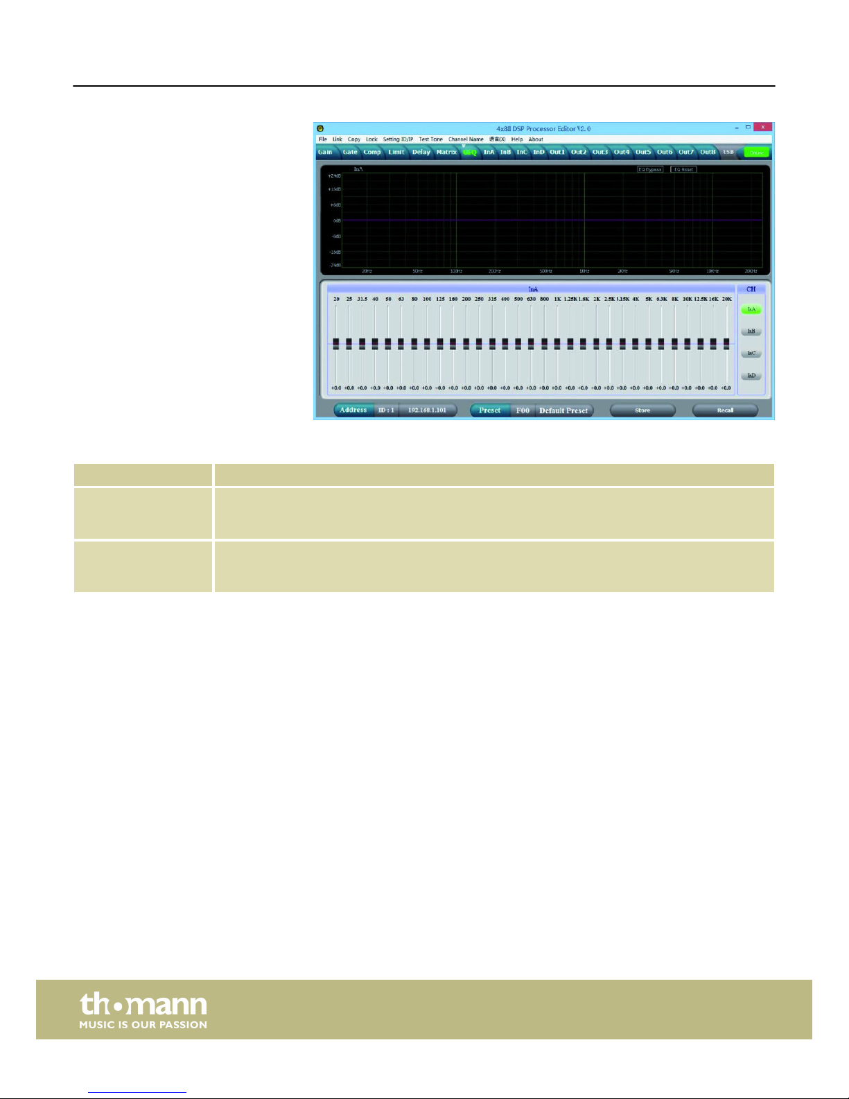
Range Meaning
Display area Shows the setting of the graphic equalizer for the selected input channel. Click on the ‘EQ Bypass’
button to temporarily switch off the equalizer function for this channel or on the ‘EQ Reset’ button to
return the equalizer to its basic status.
Control area Drag the fader with the mouse to set the boost or cut for each of the available frequency bands. To
select a channel, click on the buttons ‘InA’… ‘InD’. The number of input channels depends on the
device design.
“GEQ” tab
Control on the computer
Digital speaker management system
26
Page 27

Range Meaning
Display area Use the option fields ‘Mag’ and ‘PHASE’ to switch the diagram from Cartesian coordinates (level vs.
frequency) to polar coordinates (angle vs. frequency).
Use the option field ‘SHOW ALL EQ’ to show the parameters for all nine of the frequency bands.
Control area You can enter the parameters of the parametric equalizer for each input channel and all nine fre-
quency bands (numbered with ‘PEQ’) in the left part of the window directly as numerical values:
Centre frequency, filter quality, slope, filter type. With the ‘Bypass’ button, the equalizer for the
respective frequency band and the respective channel can be temporarily switched off.
In the middle part of the window ( ‘PEQ Parameter’) you can set the parameters centre frequency, filter
quality, and slope unit using the faders. The setting is based on the frequency band that is high-
lighted green in the left part of the window.
You can select the cut-off frequency and the filter type for the low pass and the high pass filter. Use
the ‘Bypass’ button to temporarily switch off the filter.
Drag the fader into the right part of the window using the mouse to set the level for the input
channel. The ‘Mute’ button mutes or unmutes the respective channel. The ‘Normal’/ ‘Inverse’ button
shifts the phase of the respective channel by 180° if needed.
“In” tab
Control on the computer
DSP 204, DSP 206, DSP 306, DSP 408
27
Page 28

Range Meaning
Display area Use the option fields ‘Mag’ and ‘PHASE’ to switch the diagram from Cartesian coordinates (level vs.
frequency) to polar coordinates (angle vs. frequency).
Use the option field ‘SHOW ALL EQ’ to show the parameters for all nine of the frequency bands.
Control area You can enter the parameters of the parametric equalizer for each input channel and all nine fre-
quency bands (numbered with ‘PEQ’) in the left part of the window directly as numerical values:
Centre frequency, filter quality, slope, filter type. With the ‘Bypass’ button, the equalizer for the
respective frequency band and the respective channel can be temporarily switched off.
In the middle part of the window ( ‘PEQ Parameter’) you can set the parameters centre frequency, filter
quality, and slope unit using the faders. The setting is based on the frequency band that is high-
lighted green in the left part of the window.
You can select the cut-off frequency and the filter type for the low pass and the high pass filter. Use
the ‘Bypass’ button to temporarily switch off the filter.
Drag the fader into the right part of the window using the mouse to set the level for the input
channel. The ‘Mute’ button mutes or unmutes the respective channel. The ‘Normal’/ ‘Inverse’ button
shifts the phase of the respective channel by 180° if needed.
“Out” tab
Control on the computer
Digital speaker management system
28
Page 29

8 Technical specifications
Inputs Type XLR
Level +18 dBu (max.)
Impedance 1 MΩ (stereo), 500 kΩ (mono)
Outputs Type XLR
Level +20 dBu (max.)
Impedance < 500 Ω
Frequency response 20 Hz … 20 kHz
Distortion (THD) < 0.005 % (1 kHz, 0 dBu)
Signal-to-noise ratio > 115 dBu
Crosstalk < 100 dB
Digital signal processor Resolution 24 bit
Sampling rate 96 kHz
Voltage supply
100 – 240 V 50/60 Hz
Power consumption 20 W
Fuse 5 mm × 20 mm, 2 A, 250 V, slow-blow
Dimensions (W × H × D) 480 × 45 × 24.5 mm
Weight 2.62 kg
Block diagram
Technical specifications
DSP 204, DSP 206, DSP 306, DSP 408
29
Page 30

9 Plug and connection assignment
This chapter will help you select the right cables and plugs to connect your valuable
equipment in such a way that a perfect sound experience is ensured.
Please note these advices, because especially in ‘Sound & Light’ caution is indicated:
Even if a plug fits into the socket, an incorrect connection may result in a destroyed
power amp, a short circuit or ‘just’ in poor transmission quality!
1 Ground, shielding
2 Signal (in phase, +)
3 Signal (out of phase, –)
4 Shielding on plug housing (option)
Introduction
XLR plug (balanced)
Plug and connection assignment
Digital speaker management system
30
Page 31

10 Protecting the environment
For the transport and protective packaging, environmentally friendly materials have
been chosen that can be supplied to normal recycling.
Ensure that plastic bags, packaging, etc. are properly disposed of.
Do not just dispose of these materials with your normal household waste, but make
sure that they are collected for recycling. Please follow the notes and markings on
the packaging.
This product is subject to the European Waste Electrical and Electronic Equipment
Directive (WEEE) in its currently valid version. Do not dispose with your normal
household waste.
Dispose of this device through an approved waste disposal firm or through your local
waste facility. When discarding the device, comply with the rules and regulations
that apply in your country. If in doubt, consult your local waste disposal facility.
Disposal of the packaging material
Disposal of your old device
Protecting the environment
DSP 204, DSP 206, DSP 306, DSP 408
31
Page 32

Notes
Digital speaker management system
32
Page 33

Notes
DSP 204, DSP 206, DSP 306, DSP 408
33
Page 34

Notes
Digital speaker management system
34
Page 35

Page 36

Musikhaus Thomann · Hans-Thomann-Straße 1 · 96138 Burgebrach · Germany · www.thomann.de
 Loading...