

Thetford 24571 Installation Instructions Manual
24571 Wire Replacement Package
Installation Instructions
Aqua-Magic IV High/Low Foot-Pedal Flush
manufactured after 10/19/92. (Date on Product ID
Label reads 921019 or higher.)
Tools Required
• Phillips Screwdriver
• Flat-Blade Screwdriver
•7/16" Combination Open-End, Box-End Wrench
•Needlenose Pliers
•Wire Cutters
•Allen Wrench (included in Wire Collar Package)
•Permanent Ink Marker
•Paper Towels (or shop rag to wipe grease)
Caution
Human waste contains harmful organisms which can lead to
serious diseases. Avoid exposure and always wash with an
antibacterial soap following exposure. We also recommend
safety glasses when working on this and all mechanical projects.
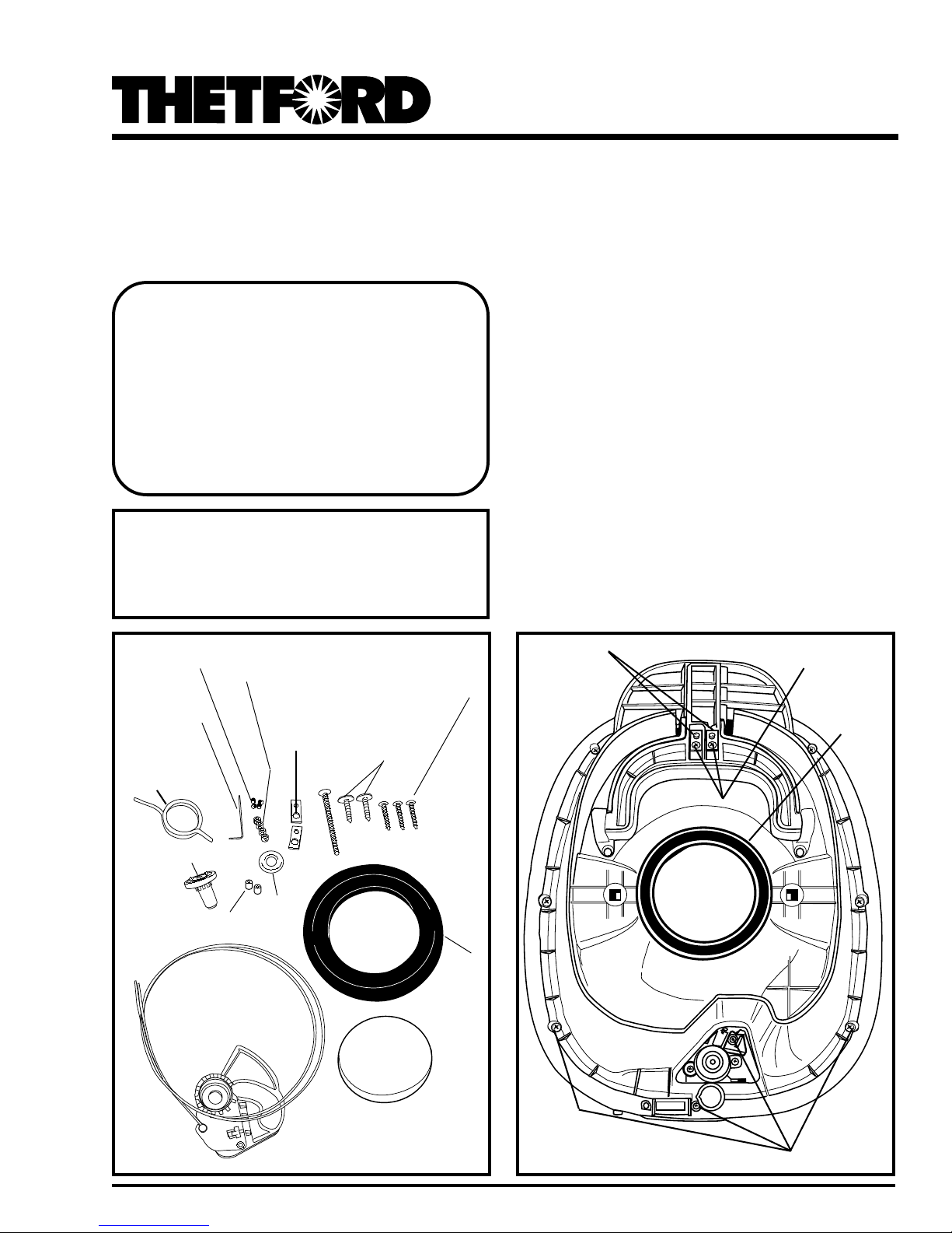
Set Screws (4)
Allen Wrench/
Clé hexagonale
Lever Return
Spring
Bearing
Wire End
Caps (2)
Lever Arm Assembly
Wire Retainer Collars
(4)
Ball Retainers
(2)
Washer
Mechanism Cover
Ball Retainer
Screws (2)
Long Screw
Outlet Cap
Screws (3)
Closet
Flange
Seal
Ball Retainers
Ball Retainer Screws
Closet Flange
Seal
Fig. 1
Parts In This Package
Fig. 2 Underside of Toilet
1
Mechanism
Cover Screws
Rev . 12/99
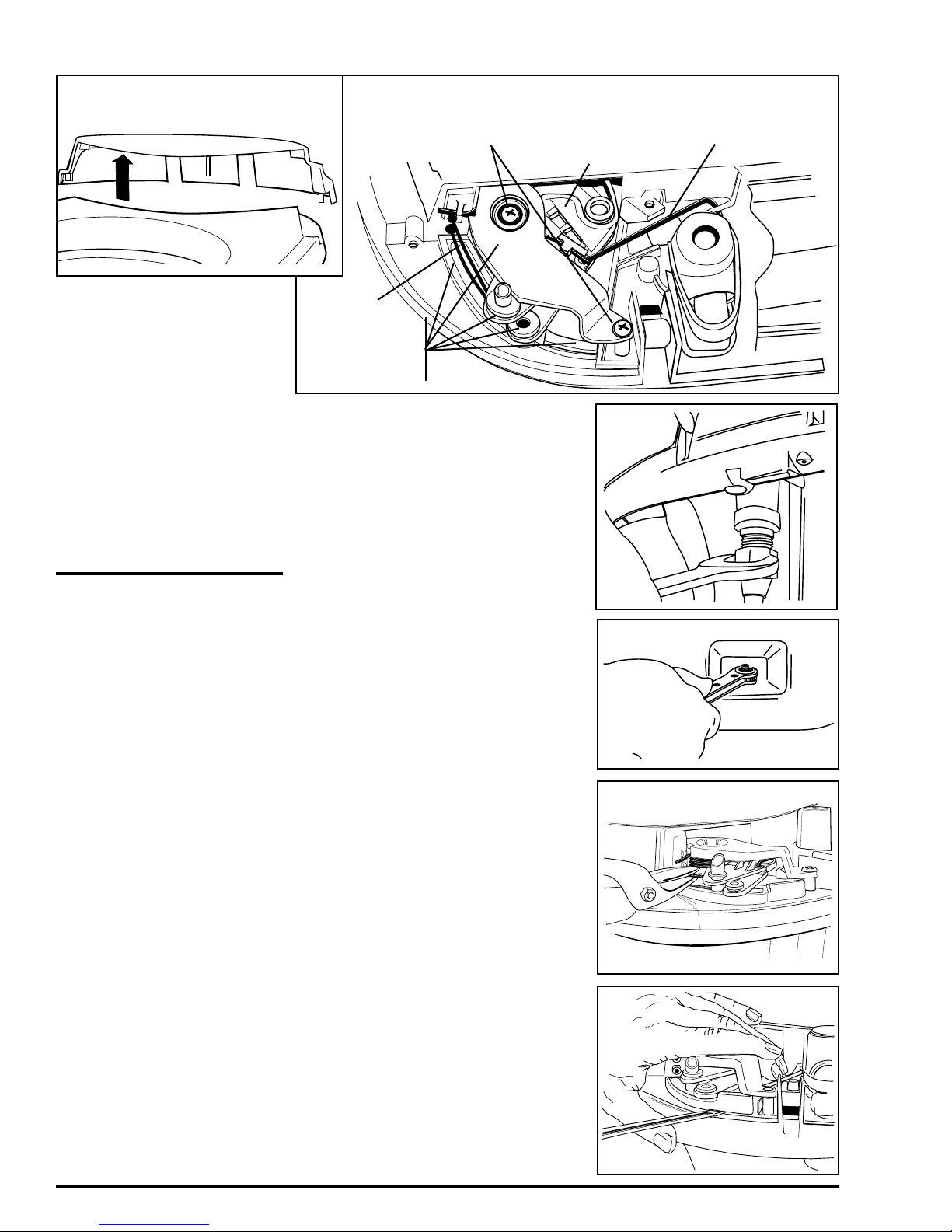
Fig. 3 – Mechanism Cover
Fig. 4 – Mechanism (Under Cover)
Lever Arm Assembly Screws
Lever Arm
Water Valve Drive Link
Section I – Removal Of
Toilet From Coach
1. Turn off water supply to toilet (see vehicle Owner’s Manual).
2. Disconnect water supply line from water valve in rear of unit
fully loosen fitting on water line avoiding excessive force and bending, which
may crack or damage water valve.
not use channel locks on Water Valve
Assembly.
3. Remove nuts from closet flange bolts
(Fig. 6)
.
4. Carefully lift and remove toilet from
closet flange.
5. Remove and discard Closet Flange Seal.
Replace with Outlet Cap.
(Fig. 5)
. Care-
Do
Section II –
Toilet Disassembly
1. Turn toilet upside down with back facing you. Place on a soft surface.
2. Remove 4 Mechanism Cover Screws
(Fig. 2)
.
3. Remove 2 Ball Retainer Screws and 2
Ball Retainers from Foot Pedals
Turn toilet upright.
4. Remove Seat and Cover (grasping both
parts together from front – lifting parts
past the normal open position).
5. Remove Mechanism Cover
(Fig. 7)
6. Cut 2 wires
7. Remove wires by tilting toilet backwards. Pull down on Foot Pedals. Push
Foot Pedals back up to expose ball ends
of wires. Pull on ball ends to remove
wires. Discard. Turn toilet upright.
8.
Release Watervalve Drive Link
Place flat blade screwdriver
derside of Link and top side of Lever
Arm Assembly. Pry upward.
9.
Remove 2 Lever Arm Assembly Screws
(Fig. 4)
.
10.
Remove (and discard) Lever Arm Assembly. Place flat blade screwdriver
tween Lower Plate of Lever Arm Assembly and flat surface of
(Fig. 8). Caution: Spring located in
ter of Lever Arm Assembly is loaded and
can release uncon
eration. Place a shop rag,
Lever Arm Assembly. Apply slight
downward pressure to shop rag while
prying up on Lever Arm Assembly.
.
Bowl. Pry upward
rollably during this op-
(Fig. 2)
(Fig. 3)
.
(Fig. 4)
between un-
be-
cen-
etc., over
Wires
Lever Arm
Assembly
Fig. 5
Fig. 6
.
Fig. 7
.
Fig. 8
2
 Loading...