

Page 1

Installation and Owner’s Instructions
Water Dispenser
This refrigerator is equipped with an optional water dispenser . The Installation Manual and the Owner’s
Manual do not include instructions about this option. Please use these instructions for the Installation and
the Operation of the water dispenser. Keep these instructions with the refrigerator Inst allation Manual
and Owner’s Manual for future use.
NORCOLD, Inc.
P.O. Box 4248
Sidney, OH 45365-4248
English
French
Norcold Customer Support Dept.
Telephone: 800-543-1219
Fax: 937-497-3183
Web Site: www.norcold.com
Part No. 629485A (8-06)
Page 2

Table of Contents
At temperatures below 0° F, store the water dispenser as
written in the “Water Dispenser Storage” section of these
instructions.
Owner’s Instructions ................................................................ 2
Water Dispenser ..................................................................... 2
Water dispenser operation ................................................. 2
Water dispenser shut off ..................................................... 3
Task light ............................................................................. 3
Drain grid and drip cup ....................................................... 3
Water dispenser cleaning and disinfecting ........................ 3
Water Dispenser Storage ................................................... 4
Replacement Parts ................................................................. 4
Wiring Pictorial ........................................................................ 4
Wiring Diagram ....................................................................... 5
Troubleshooting ..................................................................... 6
Installation Instructions ............................................................ 7
Install the Water Dispenser Components (non-metal
door models) ....................................................................... 7
Install the Water Dispenser Components (metal door
models) ............................................................................... 7
Install Decorative Door Panels (non-metal door models) ..... 7
Connect the Water Dispenser ................................................ 8
Owner’s Instructions
Water Dispenser
CAUTION: The water line heater does not protect the
water supply line from the vehicle shut off valve to the
solenoid valves on the back of the refrigerator.
Do not allow the temperature inside the refrigerator fresh food
compartment to be less than 32° F. At this temperature, the
water inside the reservoir will freeze and damage the reservoir.
If the vehicle is to shut down during cold weather, store the
water dispenser as written in the “Water Dispenser Storage”
section of these instructions.
The water dispenser operates on:
12 Volts DC.
- Potable water at a pressure of 15 psi - 125 psi.
CAUTION: Connect the water dispenser only to a
potable water supply. The dispenser system does not
make untreated water potable.
The dispenser is made to operate with water. Do not
connect the dispenser to any other beverage source.
The convenient features of the water dispenser are:
- one hand operation.
- a task light which comes on while the water dispenser is
on.
The water dispenser is assembled to the refrigerators at the
factory as optional equipment. If the refrigerator does not have
a factory installed water dispenser, one cannot be added to the
refrigerator at a later time.
The water dispenser has a water reservoir that is built into the
rear of the refrigerator fresh food compartment. As water is
dispensed, the reservoir automatically refills with water. The
reservoir allows the supply water to cool to the same temperature as the inside of the refrigerator fresh food compartment.
Most vehicle manufacturers have a water filter installed in the
plumbing system to remove odor, taste, chlorine, and sediment
from the water. If the vehicle does not already have a water filter
installed, Norcold recommends that you install one before
operating the water dispenser. Contact your dealer.
The water dispenser operates only on demand and will operate
in ambient temperatures as low as 0° F. To allow operation at
temperatures between 0° F and 32° F., the water dispenser has
a heater on the solenoid water valves and on the water line
between the solenoid valves and the water dispenser.
- a drain grid and drip cup which are removable for easy
cleaning.
- a message center, on non-metal door models) which
provides a location for notes, reminders, etc.
Water dispenser operation:
First time operation:
The first operation of the water dispenser removes the air from
the water dispenser system.
1. Remove the label from the water dispenser.
NOTE: Do not pull on the dispenser arm. If you accidently pull
the dispenser arm off of the water dispenser, make
sure the coil spring is over the round stud of the water
dispenser and press the dispenser arm onto the water
dispenser until it “snaps” into position.
2. Open the water shut off valve of the vehicle.
3. Hold a glass below the dispenser nozzle.
Owner’s Manual 2
Page 3
4. Push in and hold the dispenser arm [189] until the water flows
out in a steady stream and does not sputter (See Art01817).
NOTE: This may take a minute for the built-in reservoir to fill for the
first time and to eliminate the air from the system. You
should discard and not use the first several glasses of
water from the dispenser. New plumbing connections and/
or impurities in the water supply line from the first use or
after winterizing can cause the first glasses of water to be
discolored or have an odd flavor.
5. Release the paddle to stop the water flow.
6. Remove the glass from below the dispenser nozzle.
Continued operation:
1. Allow the water in the dispenser to cool before using the dispenser.
- The cooling time will vary with the supply water temperature.
- A complete refill of the built-in reservoir will take longer
2. Make sure that the air inside the refrigerator can freely circulate around
the water reservoir which is located at the rear of the fresh food compartment.
NOTE: Do not stack food tightly in front of the water reservoir. If the air
inside the refrigerator can not circulate around the water reservoir,
the water in the dispenser will not cool correctly. Do not set hot
food against the front of the water reservoir.
190
189
Art01817
3. Hold a glass below the dispenser nozzle.
4. Push in and hold the dispenser arm to start the water flow.
5. Release the paddle to stop the water flow.
6. Remove the glass from below the dispenser nozzle.
Water dispenser shut off:
If the water dispenser does not shut off when you release the paddle:
- Push the refrigerator ON/OFF button to turn the refrigerator off.
- See the “Troubleshooting” section of these instructions to find the
cause of the problem.
T ask light:
The task light comes on whenever the water dispenser is on.
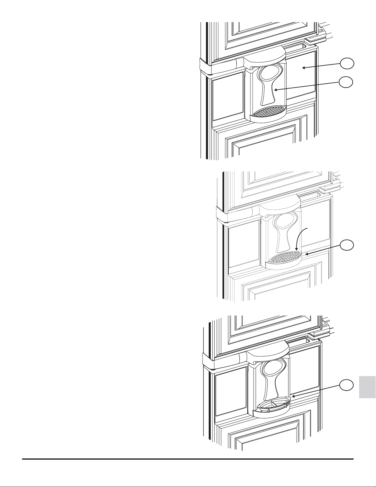
Drain grid and drip cup:
The drain grid and drip cup are located below the water dispenser
arm.
To remove the drain grid [191], push down on the center of the rear
edge of the drain grid to raise up the front edge so you can grasp it
(See Art01818).
191
Art01818
192
To remove the drip cup [192], grasp the handle area inside the drip
cup and lift it out of the well (See Art01819).
Art01819
Owner’s Manual 3
Page 4

Water dispenser cleaning and disinfecting:
To clean the drain grid and the drip cup:
- Remove the drain grid and the drip cup from the well.
- Wash the water dispenser, the drain grid, and the drip cup with a mild cleaner or a solution of liquid dish detergent and warm
water.
- Rinse with clean water.
- Dry with clean cloth.
NOTE: Do not use abrasive cleaners, chemicals, or scouring pads because they can damage the finish of the parts.
- Put the drain grid and drip cup back in the original positions.
- Follow the instructions of the RV manufacturer to disinfect the drinking water supply of the vehicle.
Occasionally food or liquid spills may fall into the reservoir area. For ease of removal and cleaning, the cover is attached to the
inside of the refrigerator with velcro. To clean the cover [194] and reservoir [195] (See Art01821):
- Remove the wire shelves and the crisper bins from the refrigerator.
- Remove the reservoir cover.
- Put your finger through the cover at a corner and gently pull the
cover forward to loosen the velcro tab at the corner.
194
- Slide your finger around the back of the cover to the next velcro
t
ab.
- Gently pull the cover forward to loosen the velcro tab.
- Repeat until the cover is removed.
- Wash the reservoir, the cover, and the area around the reservoir
with a mild cleaner or a solution of liquid dish detergent and warm
water.
- If you need to clean behind the reservoir, remove the two screws
41] that attach the reservoir to the refrigerator cabinet.
[
- Gently clean behind the reservoir.
- Put the two screws back in the original position.
41
195
Art01821
Owner’s Manual 4
Page 5

Water Dispenser Storage
43
Art01822
44
To prepare the water dispenser for seasonal storage (See Art01822):
CAUTION: Do not operate the water dispenser when the ambient air tem-
perature is 0° F. or lower. Damage to the water solenoid valves and the water
supply line can occur.
1. Close the vehicle water supply valve to the refrigerator.
2. Remove the water supply line [43] from the water solenoid valve [44].
3. Remove the water dispenser line from the water solenoid valve.
- Do not remove the foil heaters from around the water solenoid valve and the water
dispenser line
CAUTION: Drain the water dispenser. Failure to drain the dispenser can
cause damage to the dispenser components and result in leaks.
4. Drain all of the water from the water supply line and the water dispenser line.
NOTE: Make sure to use a large enough container to catch the water that drains from the dispenser water line. The water dispenser
contains almost a quart of water.
5. Put the ends of the water lines and the water solenoid valve each into a clean plastic bag.
6. Use tape to close each plastic bag around the water lines and the water solenoid valve.
To use the water dispenser after seasonal storage:
1. Remove the tape and plastic bags from the end of the water lines and the water solenoid valve.
2. Connect the dispenser water line to the water solenoid valve.
3. Connect the water supply line to the water solenoid valve.
4. Open the vehicle water supply valve to the refrigerator.
5. Push and hold the dispenser arm until the water comes out in a steady stream and does not sputter.
NOTE: You should discard and not use the first seven glasses of water from the water dispenser.
Replacement Parts
You may purchase replacement parts through your local RV dealer or authorized Norcold Service Center.
Owner’s Manual 5
Page 6

Troubleshooting
melborP
nseodretawehT
noituloS
:kcehC
-
.mrawootsiretawehT
:kcehC
.esnepsidtonseodretawehT
.ffotuhsto
:kcehC
nsidooftahT-
repmetrotaregirferehttahT-
.yltcerrocgniloocsirotaregirferehttahT-
aedruoyeeS-
posiresnepsidehtotevlavylppusretawtahT-
elosehttahT-
.yleerfsevommraresnepsidehttahT-
awelcihevehtffonruT
ehttahT-
lcevlavehttahT-
.yleerfsevomelddapresnepsid
.dezigrene-edsitinehwseso
.riovreserehtfotnorfniylthgitdekcatsto
.riovreserehtfotnorfehttsniagatonsidooftohtahT-
.retneCecivreSdlocroNdezirohtuarorel
.ne
.CDV21otdetcennocyltcerrrocsievlavretawdion
.retneCecivreSdlocroNdezirohtuarorelaedruoyeeS-
.slortnocrotaregirferehtta"FFO"rotaregirferehtnruT
.slortnocrotaregirferehtta"NO"rotaregirferehtnruT
.retneCecivreSdlocroNdezirohtuarorelaedruoyeeS-
.dellifsawriovreserresnepsidehtecnissruoh4tsaeltaneebsahtitahT
.doofhtiwgnidaolerofebsruoh8rofdetareposahrotaregirferehttahT-
.erutarepmethguonedlocaottessilortnoceruta
.nepoyllufro/dnanosiecruosretawropmupretawelcihevehttahT-
.deggolctonsimetsysylppusretawelcihevehtforetlifretawehttahT-
.
sevlavdionelosretawehtotdetcennocsienilylppusretawehttahT-
.resnepsidotecruosretawevomerropmupret
.tuodnaniyleerfsevomelddapresnepsidehtdnihebnottubdnuorllamsehttahT-
:kcehC
.d
eggolctonsimetsysylppusretawelcihevehtforetlifretawehttahT-
awehttahT-
rokaewsiwolfretawehT
.gnirettups
rodonasahretawehT
.etsatdabro
.noemoctonseodthgilksatehT
.ffoogtonseodthgilksatehT
tahT-
.htolctfosrobaws
ocroNdezirohtuarorelaedruoyeeS-
:kcehC
evehttahT-
orelaedruoyeeS-
:kcehC
-
:kcehC
idehttahT-
.yleerfsevommraresneps
.woltonsielcihevehtoterusserpretawehttahT-
.dekniktonerarotaregirferehtdnihebsenilret
.nepoylluferaresnepsidehtehtgnidaelsevlavretawyna
.senilretawelcihevehtmorfdegrupsirialla,retlifretawehtgnicalperrogniziretniwretfatahT-
osfI.stisopedlarenimpudliubevahtonseodelzzonresnepsidehtfopitehttahT-
.retneCecivreSdl
.decalperebotdeenyamretlifretawelcih
.dellatsniebotdeenyamretlifretawelcihevatahT-
.dezitinasebotdeenyammetsysretawelcihevehttahT
.retawfosessalglarevestuogninnurybdegrupsiriovreserresnepsidehttahT-
.retneCecivreSdlocroNdezirohtuar
.CDV21otdetcennocyltcerrrocsievlavretawdionelosehttahT
.retneCecivreSdlocroNdezirohtuarorelaedruoyeeS-
.retneCecivreSdlocroNdezirohtuarorelaedruoyeeS-
ahtiwnaelc
31710trA
Owner’s Manual 6
Page 7

Installation Instructions
Install the W ater Dispenser Component s (non-metal door models)
1. Install the back splash assembly (See
Art01820):
- Put the hook on the bottom of the back splash
assembly [193] down into the slot [157] of the
water dispenser panel.
- Align the two (2) rectangular mounting studs on
the rear of the back splash assembly with the
two (2) mounting lugs [196] on the water
dispenser panel.
- Using equal pressure, push both mounting
studs into the mounting lugs at the same time.
- The mounting studs should engage and lock
into the mounting lugs with a “click” sound.
Install the W ater Dispenser Components (metal door models)
1. Install the back splash assembly (See
Art01820):
- Put the hook on the bottom of the back splash
assembly [193] down into the slot [157] of the
water dispenser panel.
- Align the two (2) rectangular mounting studs on
the rear of the back splash assembly with the
two (2) mounting lugs [196] on the water
dispenser panel.
- Using equal pressure, push both mounting
studs into the mounting lugs at the same time.
- The mounting studs should engage and lock
into the mounting lugs with a “click” sound.
193
196
157
Art01820
Owner’s Manual 7
Page 8

Install Decorative Door Panels (non-metal door models)
NOTE: The doors are made to accept decorative panels. The decora-
tive panels must be 3/16 inch or less in thickness. Install the
decorative door panels in the refrigerator doors before installing the refrigerator in the vehicle.
1. Make two upper door panels that are 17 1/4 inches wide x 23 1/8
inches high:
- Raised panels must be centered on each door and no larger than
16 1/2 inches wide x 22 3/8 inches high.
2. Make a lower RH door panel that is 17 1/4 inches wide x 42 5/16
inches high:
- Raised panels must be centered on the lower RH door and no
larger than 16 1/2 inches wide x 41 9/16 inches high.
3. Make a lower LH door panel that is 17 1/4 inches wide x 34 5/8
inches high:
- Raised panels must be centered on the lower LH door and no larger
than 16 1/2 inches wide x 33 7/8 inches high.
4. Install the decorative door panels:
- Pull the panel retainer [37] off of each door [39] (See Art01804).
- Push a decorative door panel [38] into the slots of each door.
38
39
37
Art01804
37
- Make sure that each panel retainer is correctly positioned and push the
curved snap [125] of the panel retainer [37] inside of the curved snap
[126] of the door (See Art01805).
- Make sure that the decorative door panel [36] of the lower LH refrigera-
tor door is behind the water dispenser panel.
125
Art01805
126
Owner’s Manual 8
Page 9

Connect the Water Dispenser
43
Art01822
44
The water dispenser is assembled to the refrigerator at the factory as optional equipment. If the refrigerator does not have a factory
installed water dispenser, one can not be added to the refrigerator at a later time.
The refrigerator installer must connect a cold water supply line to the solenoid valve at the rear of the refrigerator. The following are
necessary to connect the water dispenser.
- 1/4 in. OD copper tubing for the water supply line.
OR
- 1/4 in. OD plastic tubing for the water supply line.
- 1/4 in. shut off valve in the water supply line. This should be easily accessible through the lower intake vent.
Connect the water supply line:
Install a 1/4 in. OD water supply line [43] from the water shut off valve of the vehicle to
the solenoid water valve [44] at the rear of the refrigerator (See Art01822):
NOTE: A brass compression nut [45], a brass sleeve, a plastic sleeve [46], and a
brass insert [47] are supplied and attached to the rear of the refrigerator (See
Art01702).
- Put the compression nut and then the sleeve onto the water supply line [43].
- For copper tubing, use the brass sleeve.
- For plastic tubing, use the plastic sleeve [46].
- For plastic tubing with .040 in. wall thickness, also use the brass insert [47].
- Flush the water supply line until the water is clear.
- Put the water supply line into the compression fitting of the solenoid valves.
- Tighten the compression nut by hand (hard finger tight).
- Using two wrenches, tighten the compression nut 1 ½ to 2 turns.
- Open the water shut off valve of the vehicle.
- Examine the connections for leaks.
47
46
45
Art01702
43
Owner’s Manual 9
Page 10

Owner’s Manual 10
 Loading...