

Page 1
Motor Replacement Package
RV Toilet Service Parts
for Aria/Aria Deluxe
Tools needed
• Flat-blade screwdriver • Adjustable Wrench
• Small Flat-blade screwdriver • Pliers
Note:
• Read all instructions before beginning work.
To Remove Toilet From Floor
1. Turn off RV water supply per RV Owner’s Manual.
2. Press both keypad buttons at the same time, twice, to open
blade and drain bowl of water.
you will have to open the valve manually. Remove the Sound
Deadening insulation (if present) from the back of the
mechanism to access the mechanism lead screw. Use a
5/16” socket wrench to turn the screw and open the valve.
3. Pry off Bolt Caps with Flat-blade screwdriver. Use wrench
to remove 1/2-inch Lag Screws.
4. Swivel Toilet to gain access to back.
5. Turn off RV’s power supply to the Toilet.
6. Disconnect Toilet’s 12-volt power hookup to RV.
7. Disconnect Water Supply Line from elbow connector by
hand. Use Adjustable Wrench if necessary, with care.
8. Place an old towel or soft cloth on work surface. Remove
Toilet from floor and place upside-down on work surface.
9. Remove old Closet Flange Seal (may be found in toilet or in
floor at Closet Flange). Discard.
10. Cover Holding Tank opening to contain odor.
If mechanism does not work,
To Remove Old Part
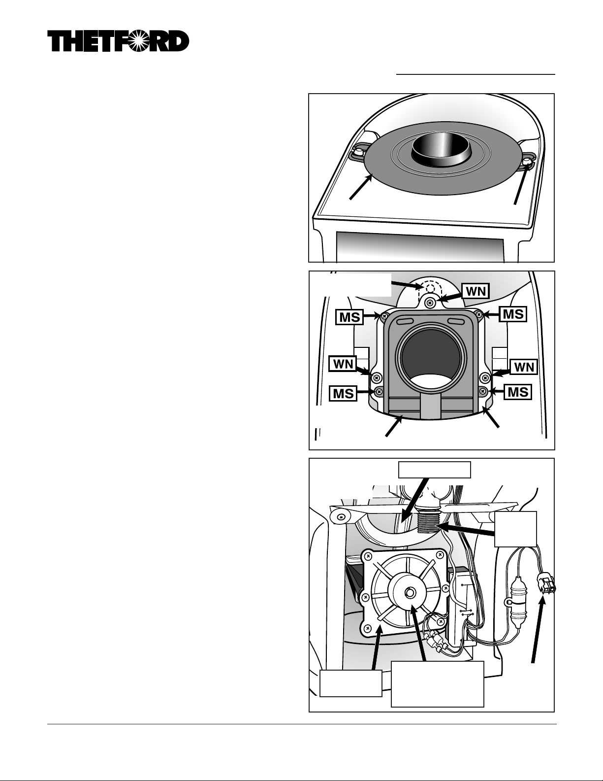
1. Tap out 2 Mounting Bushings (Fig. A).
2. Remove Mounting Flange (Fig. A).
3.
High Profile models only:
be found connected to Mounting Flange or to the Mechanism. Remove Tube Seal (Fig. G).
(You may want to turn the toilet right side up to continue.)
4. Remove and save Sound Deadening Kit insulation from
around mechanism. The cylindrical pad at the rear of the
Mechanism may be left in place (Fig. C).
5.
Remove 4 Mechanism Screws (without Washers) (MS, Fig. B).
6. Disconnect 2 green/yellow wires from Mechanism Assembly at spade connectors. Use pliers if necessary.
7. Lift Mechanism Assembly off. Pull carefully out through back
of Toilet.
8. Remove Overflow Tube from Mechanism Assembly (Fig. C).
9. Remove, save 6 End Cap Bolts. Remove End Cap (Fig. C).
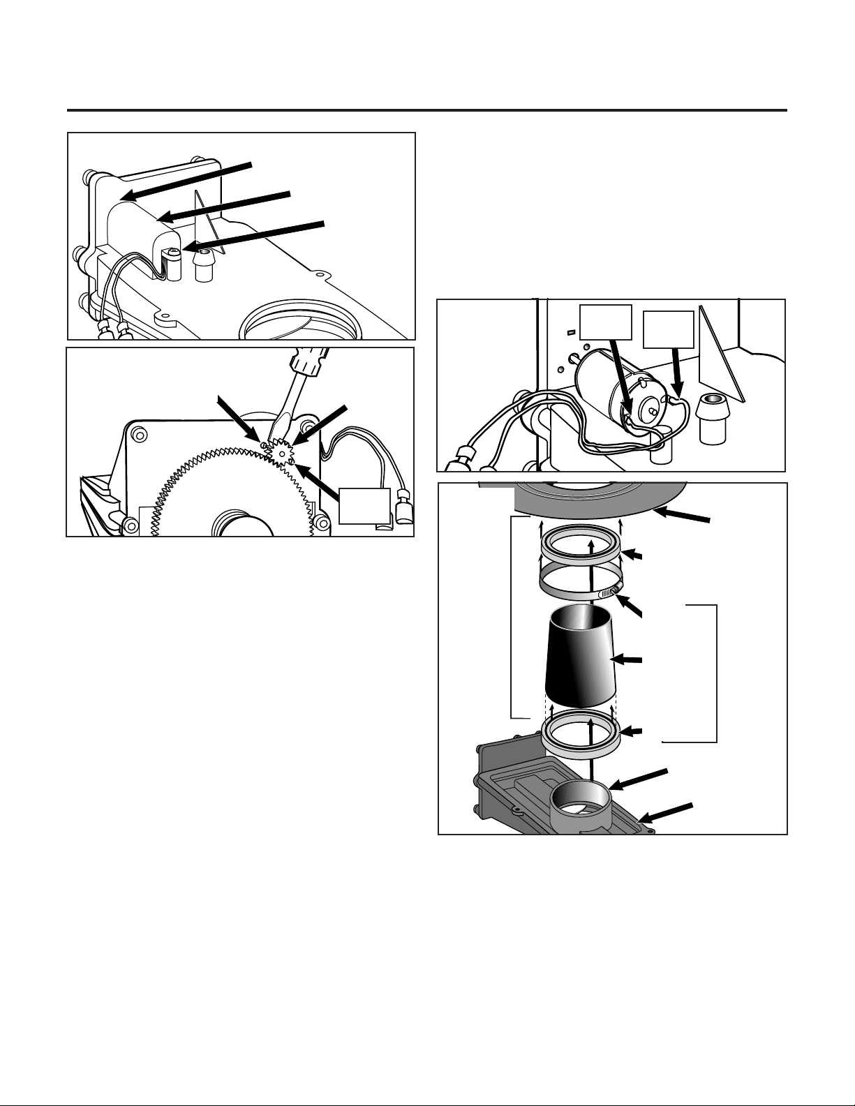
10. Remove screw to remove Motor Cover (Fig. D).
11.
Using Screwdriver, gently pry off small Pinion Gear (Fig. E). Discard.
Remove Extension Tube. It may
Fig. A
Mounting Flange
newer plates have
a 2nd hole at front
Fig. B
Mechanism
Fig. C
Mechanism
End Cap
Part #19622
Mounting Bushing
White Mechanism Plate
Overflow Tube
Sound Deadening
Cylindrical Insulator
(not present on all
models)
Water
supply
hookup
Power
supply
connector
Form #19640 Rev. 10.1.01
Page 2
Part #19622
Motor Replacement Package
Continued
Fig. D
Fig. E
Small
screw
Motor Cover Tab
Motor Cover
Screw
Small
screw
Pinion
Gear
cone Grease.
f. Install Mounting Flange and Seal assembly on Extension
Tube. Make sure there is at least a 1/2” overlap between the
Extension Tube and Mounting Flange Seal.
Low Profile:
of the Mounting Flange. Install Mounting Flange to Mechanism. (No extension tube is used.)
10. Replace 2 Mounting Bushings with flat surface out.
Fig. F
Fig. G
Replace the Mounting Flange Seal onto the lip
Green
Wire
Yellow
Wire
Mounting
Flange
12. Using small, Flat-blade screwdriver, remove 2 Screws that
connect Motor to Front Flange. Remove Motor. Discard.
To Replace Part
1. Position new Motor, lining up 2 Screw holes and with wires
as shown in Fig. F . Replace Screws and tighten.
2. To replace Pinion Gear, line up D shape of Motor shaft and
Gear. Rotate Drive Gear slightly to align teeth of Pinion Gear.
Press on. Must be fully engaged with Drive Gear.
3. Replace Motor Cover, lining up tab with slot (Fig. D). Do not
pinch wires. Reinstall Motor Cover Screw.
4. Reinstall End Cap. Secure 6 Screws.
5. Reattach Overflow Tube to Mechanism.
6.
Reattach 2 Wire Motor Leads, yellow to yellow and green to green.
7. Position Blade Seal over Mechanism Plate.
8. Insert Mechanism into Toilet, tucking wires behind Mechanism. Line up and secure 4 Mechanism Screws (Fig. B).
9.
High Profile:
a. Lubricate sealing surface of Extension Tube Seal with silicone grease.
b. Install Extension Tube Seal on Extension Tube.
c. Install Extension Tube and seal assembly on Mechanism.
Make sure that seal is seated at least 1/2 inch below Mechanism tube lip.
d. Ensure Hose Clamp on Mounting Flange Seal is tight.
e. Lubricate Mounting Flange Seal sealing surface with Sili-
To install Extension Tube (Refer to Fig. G):
Shown
separate
Mounting
Flange Seal
for clarity
– these
items
Clamp
normally
remain
as-
sembled
Extension
Tube
Extension
Tube Seal
Mechanism
Tube Lip
HIGH
PROFILE
ONLY
Mechanism
To Replace Toilet To Floor
1. Secure new Closet Flange Seal, lip side up, to Toilet.
2. Position Toilet over flange.
3. Reconnect Water Supply Line.
4. Reconnect 12-volt power supply to Toilet.
5. Reconnect RV’s power supply to the Toilet.
6. Secure to floor with Lag Screws. Tighten.
7. Turn on RV’s water supply. Press Toilet flush button to close
blade and to flush test.
8. Resecure Bolt Caps.
 Loading...