

Page 1
RV Toilet Service Parts
for
Aria Deluxe II
Tools needed
• Flat-blade screwdriver • Pliers
• Adjustable Wrench
• DAP Dynaex Caulk or equivalent (available at most hardware
stores)
Note:
• Read all instructions before beginning work.
•
You may not need to replace all the Seals in this package.
• All replacements will require removing toilet from oor.
• Use gloves when handling parts that may have come in contact
with waste.
To Remove Toilet From Floor
1. Turn off RV water supply per RV Owner’s Manual.
2. Press both keypad buttons at the same time, twice, to open blade
and drain bowl of water.
3. Pry off Bolt Caps with Flat-blade screwdriver. Use wrench to
remove 1/2-inch Lag Screws.
4. Swivel Toilet to gain access to back.
5. Turn off RV’s power supply to the Toilet.
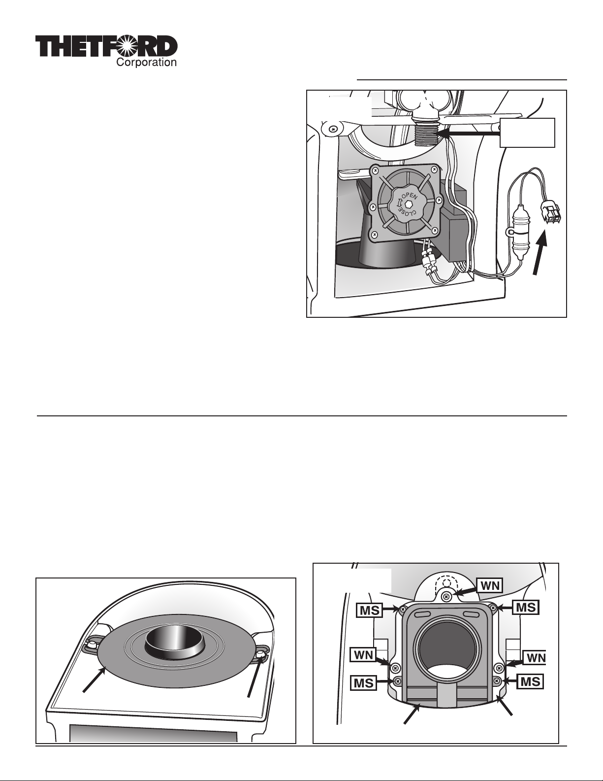
6. Disconnect Water Supply Line with Adjustable Wrench (Fig. A).
7. Disconnect Toilet’s 12-volt power hookup to RV.
Seal Replacement Package
Part #19621
Fig. A
Water supply
hookup
Power supply
connector
8.
Place an old towel or soft cloth on work surface. Remove Toilet from oor
and place upside down on work surface.
9. Remove old Closet Flange Seal (may be found in toilet or in oor
at Closet Flange). Discard.
10. Cover Holding Tank opening to contain odor.
Replacement of Blade Seal, O Ring Seal and Hopper Seal
To Remove Parts
1. Tap out 2 Mounting Bushings (Fig. B).
2. Remove Mounting Flange and Flange Seal.
3. High Prole models only: Remove Extension Tube. It may
be found connected to Mounting Flange or to the Mechanism.
Remove Tube Seal.
4.
if you need to replace the Blade Seal, remove 4 Mechanism Screws
without Washers (MS, Fig. C). If not, remove the three screws shown
with washers (no arrows).
Fig. B
Mounting Flange
Mounting Bushing
5. Lift Mechanism Assembly off Seal. Pull out carefully through back
of toilet, just far enough to gain access to the seal(s) to be replaced.
(No need to disconnect/remove motor wiring, Overow Tube or
Sound Deadening Insulation – if present – from Mechanism.)
To Replace Blade Seal
1. Remove Blade Seal (may be attached to white Mechanism Plate).
Discard. Fit new seal in its place.
Fig. C
Form #19639B
Mechanism
White Mechanism Plate
Rev. 01/22/08
Page 2
Part #19621
Seal Replacement Package Page 2
To Replace O-Ring Seal
If you do not need to replace this seal, skip down to Re-install Mechanism sec-
tion below.
It is not necessary to remove Mechanism from toilet to install this seal. If you decide
to remove it, disconnect the Overow tube from top of Mechanism by twisting it off.
Then disconnect the yellow and green Motor Lead, using pliers if necessary.
1. Remove the Sound Deadening Kit insulation (if present) from Mechanism by
unwrapping the VelcroTM strap.
2. R
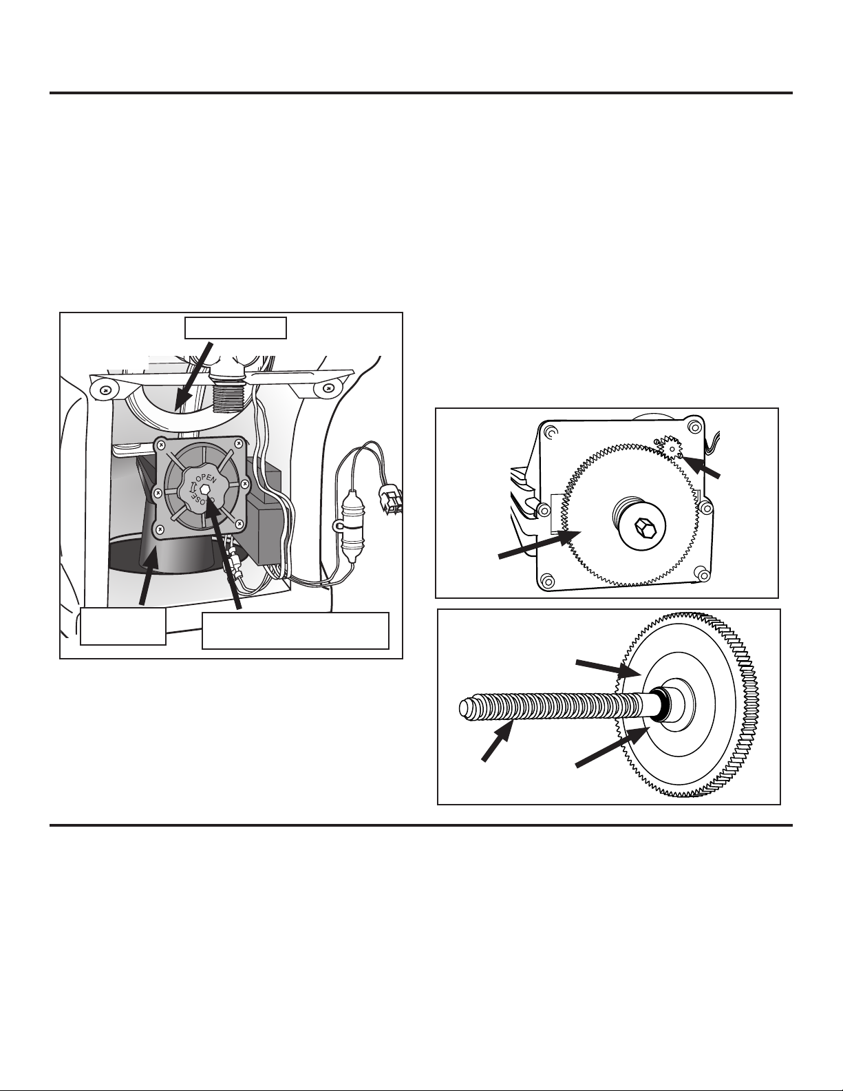
emove 6 End Cap Bolts from Mechanism. Remove End Cap (Fig. D).
3.
Grasp Gear/Clutch Assembly (Fig. E) and pull it out of the housing. This retracts
Fig. D
Overow Tube
Lead Screw into the Valve Blade. Release the Valve Blade. (Caution: wear
gloves when handling Valve Blade or anything that may have
come in contact with waste.)
7. Re-engage the large gear with the small pinion gear (Fig .E) and slide the Gear/
Clutch/Lead Screw Assembly fully into the housing.
8. Make sure curved washer is in place on the Lead Screw, concave side facing
toilet. Reinstall End Cap and secure 6 Screws.
9. Replace the Sound Deadening Kit insulation (if present) onto Mechanism, securing
it with the VelcroTM strap.
If you have removed Mechanism from toilet, do these steps now:
1. Reattach Overow Tube to Mechanism.
2.
Reattach 2 Wire Motor Leads, yellow to yellow and green to green.
Fig. E
Pinion
Gear
Mechanism
End Cap
the Valve Blade fully. The Lead Screw (Fig. F) is engaged in the Lead Screw
Boss on the Valve Blade (not shown).
4.
Turn Lead Screw counterclockwise until it releases from the Valve Blade.
Withdraw the entire Gear/Clutch/Lead Screw Assembly.
5. On the back side of the Gear/Clutch subassembly (Fig. F) you will nd a small
black “O” Ring. Slide it off and replace it with the new one.
6. Slide the Gear/Clutch/Lead Screw Assembly back into the housing. Holding
the Valve Blade, turn Lead Screw clockwise enough turns to fully engage the
Mechanism Lead Screw (knob
shown not on all units)
To Replace Hopper (Bowl Opening) Seal
If you do not need to replace this seal, skip down to Re-install Mechanism
section below.
1. Unscrew 3 Well Nut Screws with Washers (shown without arrows in Fig. C, page
1) to free white Mechanism Plate.
2. Scrape off old Seal on china with sharp tool. Use mineral spirits to remove
residue.
3. Apply a generous ring of caulk sealant around Bowl Drain opening (Fig. G, next
page).
4. Apply Flat Foam Seal to caulk sealant. Press down in place, center the seal, and
Gear/clutch assembly
Fig. F
Gear/clutch assembly
Lead
Screw
wipe away any excess sealant squeezed into opening.
To Replace Mechanism
1. Wet blade seal with clean water.
2. Fully seat new blade seal, lip up, onto Mechanism Plate (Fig. G).
3. To avoid damaging blade seal, make sure blade in new mechanism is fully closed.
Turn mechanism lead screw counter-clockwise to close valve (Fig. D).
4. Connect 2 Motor Leads, yellow-yellow, green-green (Fig. A).
5. Working from the back, position Mechanism in Toilet. NOTE: on
“O” Ring
Seal
Page 3

Part #19621
Seal Replacement Package Page 3
some low-prole units, it may be a tight squeeze. Align mechanism over Mecha-
nism Plate, press down and secure with four screws (MS, Fig. D).
6. Turn toilet over to check centering. Loosen well-nuts to re-center if needed.
Do the permanent tightening down of the well-nut screws at this
time by hand. Tighten in a diagonal pattern to get an even seal. Be
careful not to overtighten and cause deection of the plate at the
edges. Wipe off excess sealant when done.
7. Cut approximately 1” off Overow Tube. Forming a full loop, reattach to
Mechanism. Tuck in and away from lead screw.
8. If you removed the Controller Assembly and/or the Switch Box, re-install
now, using the adhesive foam pads provided. If you removed Metal
Bracket, reinstall.
9. High Prole: To install Extension Tube (Refer to Fig. H):
a. Lubricate sealing surface of Extension Tube Seal with silicone
grease.
b. Install Extension Tube Seal on Extension Tube.
Fig. H
Shown
separate for
Mounting
Flange Seal
Mounting
Flange
clarity – these
items nor-
mally remain
Clamp
assembled
Extension
Tube
HIGH
PROFILE
ONLY
Extension
Tube Seal
Mechanism
Tube Lip
Fig. G
Blade
Seal
Mechanism
Lead Screw
Mechanism
Plate
Well-nut
ass’y
Flat Foam
Seal
Sealant
c. Install Extension Tube and seal assembly on Mechanism. Make sure
that seal is seated at least 1/2 inch below Mechanism tube lip.
d. Ensure Hose Clamp on Mounting Flange Seal is tight.
e. Lubricate Mounting Flange Seal sealing surface with Silicone
Grease.
f. Install Mounting Flange and Seal assembly on Extension Tube. Make
sure there is at least a 1/2” overlap between the Extension Tube
and Mounting Flange Seal.
Low Prole: Replace the Mounting Flange Seal onto the lip of the
Mounting Flange. Install Mounting Flange to Mechanism. (No extension
tube is used.)
10. Replace 2 Mounting Bushings with at surface out.
Mechanism
Replacing Flush Nozzle Seals
This does not require removing the Mechanism.
To Remove Old Parts
1. Disconnect 2 upper Tubes from outside Nozzle Connectors (Fig.
I).
2. Cut Tie Strap securing Solenoid Valve to Metal Bracket (Fig. J).
3. Being careful not to bend Metal Bracket, slide Solenoid Valve out
of slot in Bracket. Swing entire Valve/Hose Assembly down and to
right out of the way. Support it to avoid putting stress on the Wire
Harness.
4. Pop up Seat/Lid Bolt Covers (hinged from rear).
Fig. I
Hinge Post Bolts
Locking
Nut
Outside Nozzle Connectors
Page 4

Part #19621
Seal Replacement Package Page 4
5. Holding Hinge Post Nuts from inside (Fig. J), turn screwdriver
counterclockwise to unscrew Hinge Posts. Remove Nuts and Bolts
(but not Seat/Lid).
6. Take note of Overow Tube position for future reference. Pull
Overow Tube off center Nozzle Connector.
7. To remove 2 outside Nozzle Connectors (Fig. I), push them in,
twist counterclockwise and pull back. (They may be caulked tight
and difcult to remove. Use pliers if necessary.)
8. Remove Locking Nut from center Nozzle by turning counterclock-
wise until it releases. Save Locking Nut.
9. Scrape away 3 Seals and Sealant with a sharp-edged tool. Use
mineral spirits to remove all residue from china.
To Replace Parts (Fig. K)
1. Push small Foam Seal over Flush Cover barb. Position new Flush
Cover/Nozzle Assembly in bowl. (Be sure Foam Seal is stuffed
completely/ush into opening.)
2. Place Locking Nut on center Nozzle. Holding Nozzle Assembly
rmly in position from inside Toilet Bowl, Turn Locking Nut clock-
wise to lock. (Note: all 4 prongs must mate with locking ears to
achieve proper lock.)
3. Adhere Nozzles to Connectors. Again Holding Nozzle Assembly
rmly, push in hard and rotate clockwise (you will feel it lock).
4. Reattach center Overow Tube. Tuck in Tube. To form a water
trap, it must be curved at approximately same position as when
removed.
5. Align/adjust Flush Cover/Nozzle Assembly level to Toilet inside
bowl.
6. Align Seat/Cover Assembly. Replace Hinge Posts and reattach
Nuts. Tighten rmly (Fig. J).
7. Swing entire Valve/Hose Assembly upright. Holding Metal Bracket
rmly to avoid bending it, slide Solenoid Valve back into slot in
Bracket. Rearrange Wire Harness.
8. Reconnect Hoses to outside Flush Nozzles. Push on rmly (Fig.
J).
9. Attach new Tie Strap holding Solenoid Valve to Metal Bracket (Fig.
K).
Fig. J
Overow Tube
Fig. K
Nozzle As-
sembly
Back wall of
china bowl
Hinge
Post
Bolts
Nozzle
Gasket
Nozzle Connector
Water Solenoid Valve
Tie Strap
Metal Bracket
Foam
Nozzle
Seal
Nozzle Con-
nector
Locking Nut
To Replace Toilet To Floor
1. Secure new Closet Flange Seal, lip side up, to Toilet.
2. Position Toilet over ange.
3. Reconnect Water Supply Line.
4. Reconnect 12-volt power supply to Toilet.
5. Reconnect RV’s power supply to the Toilet.
6. Turn on RV’s water supply. Press Toilet ush button to close blade
and to ush test.
7. Secure to oor with Lag Screws. Tighten.
8. Resecure Bolt Caps.
 Loading...