

Page 1

E4-130, E4-250
power amplier
user manual
Page 2

Musikhaus Thomann
Thomann GmbH
Hans-Thomann-Straße 1
96138 Burgebrach
Germany
Telephone: +49 (0) 9546 9223-0
E-mail: info@thomann.de
Internet: www.thomann.de
10.04.2019, ID: 348232, 348233 (V3)
Page 3

Table of contents
1 General information................................................................................................................................. 4
1.1 Further information........................................................................................................................... 5
1.2 Notational conventions.................................................................................................................... 6
1.3 Symbols and signal words............................................................................................................... 6
2 Safety instructions..................................................................................................................................... 8
3 Features....................................................................................................................................................... 13
4 Installation and starting up................................................................................................................ 14
5 Connections and operating elements........................................................................................... 19
6 Technical specications....................................................................................................................... 25
7 Plug and connection assignment.................................................................................................... 30
8 Cleaning....................................................................................................................................................... 33
9 Protecting the environment.............................................................................................................. 34
Table of contents
E4-130, E4-250
3
Page 4

1 General information
This user manual contains important information on the safe operation of the device. Read and
follow all safety notes and all instructions. Save this manual for future reference. Make sure
that it is available to all persons using this device. If you sell the device to another user, be sure
that they also receive this manual.
Our products and user manuals are subject to a process of continuous development. We there‐
fore reserve the right to make changes without notice. Please refer to the latest version of the
user manual which is ready for download under www.thomann.de.
General information
power amplier
4
Page 5
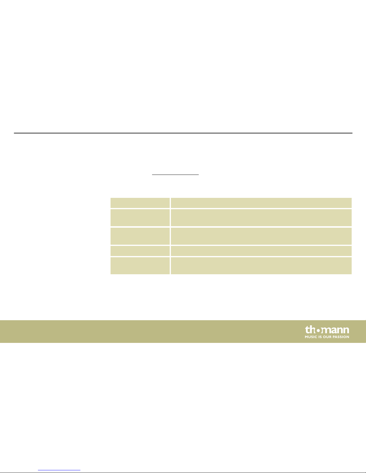
1.1 Further information
On our website (www.thomann.de) you will nd lots of further information and details on the
following points:
Download This manual is also available as PDF le for you to download.
Keyword search
Use the search function in the electronic version to nd the topics of
interest for you quickly.
Online guides
Our online guides provide detailed information on technical basics
and terms.
Personal consultation For personal consultation please contact our technical hotline.
Service
If you have any problems with the device the customer service will
gladly assist you.
General information
E4-130, E4-250
5
Page 6

1.2 Notational conventions
This manual uses the following notational conventions:
The letterings for connectors and controls are marked by square brackets and italics.
Examples: [VOLUME] control, [Mono] button.
1.3 Symbols and signal words
In this section you will nd an overview of the meaning of symbols and signal words that are
used in this manual.
Letterings
General information
power amplier
6
Page 7
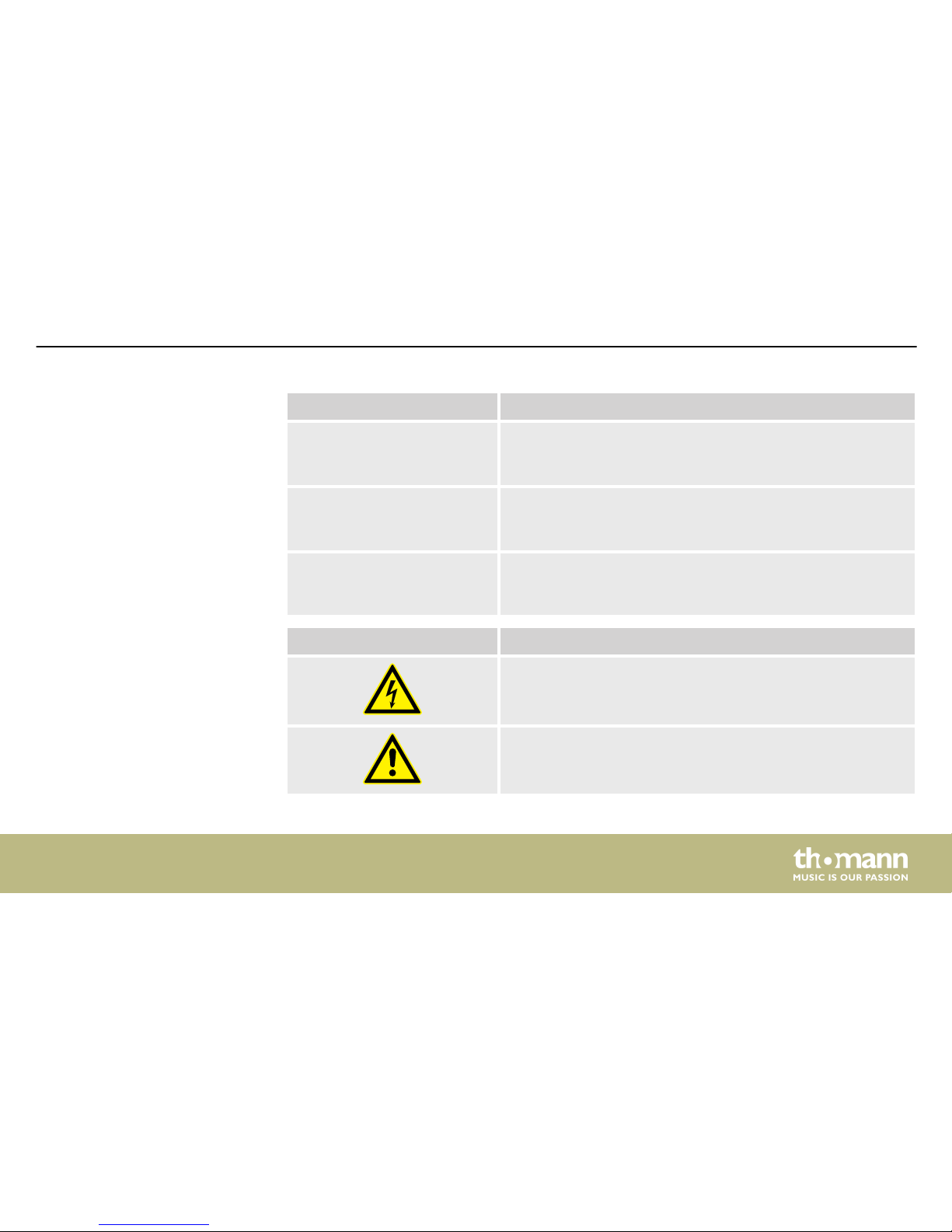
Signal word Meaning
DANGER! This combination of symbol and signal word indicates an
immediate dangerous situation that will result in death or
serious injury if it is not avoided.
CAUTION! This combination of symbol and signal word indicates a pos‐
sible dangerous situation that can result in minor injury if it
is not avoided.
NOTICE! This combination of symbol and signal word indicates a pos‐
sible dangerous situation that can result in material and
environmental damage if it is not avoided.
Warning signs Type of danger
Warning – high-voltage.
Warning – danger zone.
General information
E4-130, E4-250
7
Page 8
2 Safety instructions
This device amplies electric audio frequency signals to operate passive speakers. Use the
device only as described in this user manual. Any other use or use under other operating con‐
ditions is considered to be improper and may result in personal injury or property damage. No
liability will be assumed for damages resulting from improper use.
This device may be used only by persons with sucient physical, sensorial, and intellectual
abilities and having corresponding knowledge and experience. Other persons may use this
device only if they are supervised or instructed by a person who is responsible for their safety.
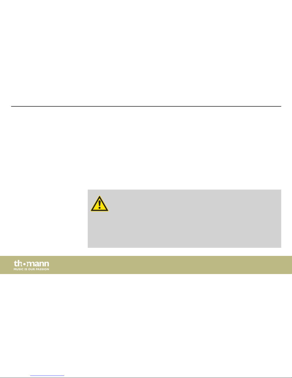
DANGER!
Danger for children
Ensure that plastic bags, packaging, etc. are disposed of properly and are not
within reach of babies and young children. Choking hazard!
Ensure that children do not detach any small parts (e.g. knobs or the like) from
the unit. They could swallow the pieces and choke!
Never let children unattended use electrical devices.
Intended use
Safety
Safety instructions
power amplier
8
Page 9
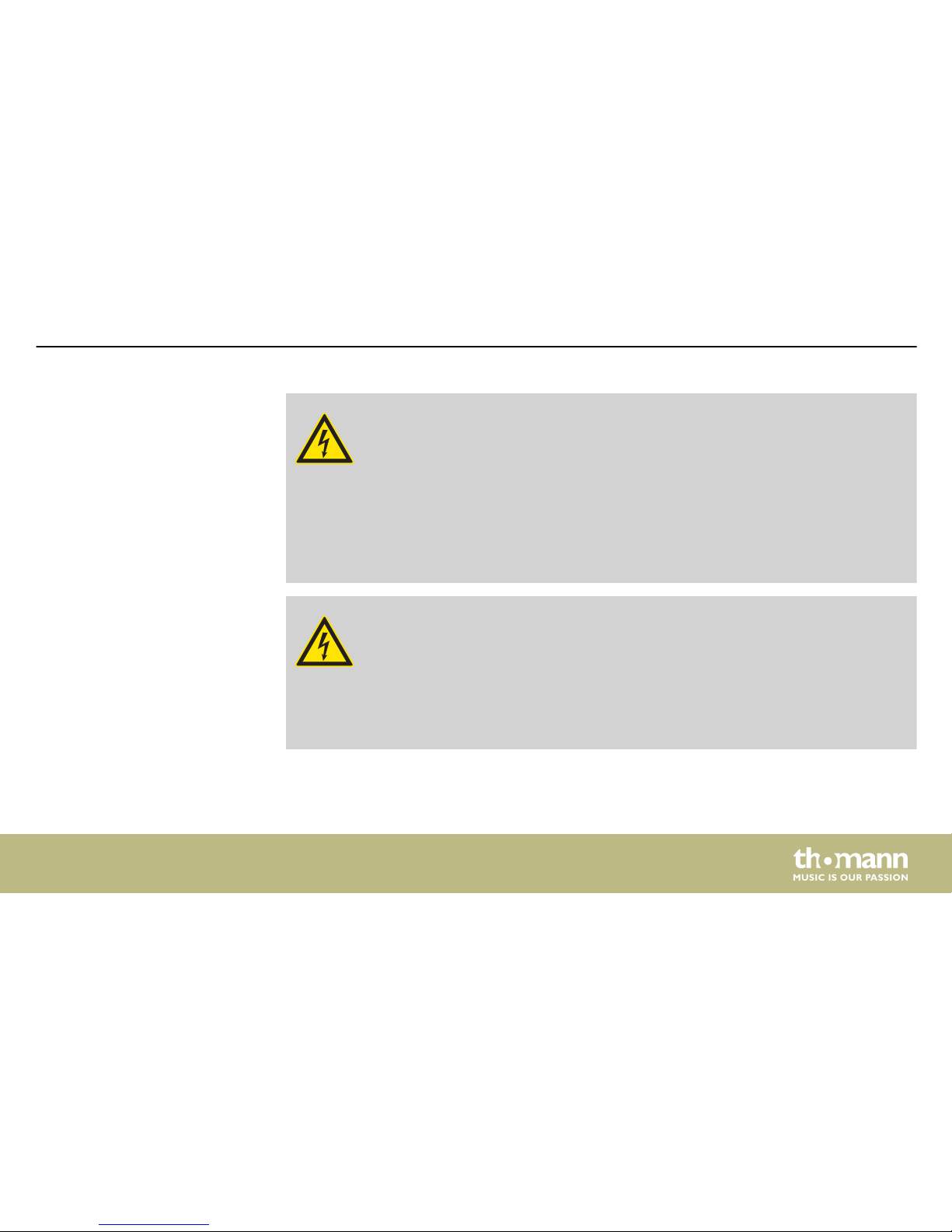
DANGER!
Electric shock caused by high voltages inside
Within the device there are areas where high voltages may be present. Never
remove any covers.
There are no user-serviceable parts inside.
Do not use the device if covers, protectors or optical components are missing or
damaged.
DANGER!
Electric shock caused by short-circuit
Always use proper ready-made insulated mains cabling (power cord) with a pro‐
tective contact plug. Do not modify the mains cable or the plug. Failure to do so
could result in electric shock/death or re. If in doubt, seek advice from a regis‐
tered electrician.
Safety instructions
E4-130, E4-250
9
Page 10
CAUTION!
Possible hearing damage
With loudspeakers or headphones connected, the device can produce volume
levels that may cause temporary or permanent hearing impairment.
Do not operate the device permanently at a high volume level. Decrease the
volume level immediately if you experience ringing in your ears or hearing
impairment.
NOTICE!
Risk of re
Do not block areas of ventilation. Do not install the device near any direct heat
source. Keep the device away from naked ames.
Safety instructions
power amplier
10
Page 11

NOTICE!
Operating conditions
This device has been designed for indoor use only. To prevent damage, never
expose the device to any liquid or moisture. Avoid direct sunlight, heavy dirt, and
strong vibrations.
Only operate the device within the ambient conditions specied in the chapter
‘Technical specications’ of this user manual. Avoid heavy temperature uctua‐
tions and do not switch the device on immediately after it was exposed to tem‐
perature uctuations (for example after transport at low outside temperatures).
Dust and dirt inside can damage the unit. When operated in harmful ambient
conditions (dust, smoke, nicotine, fog, etc.), the unit should be maintained by
qualied service personnel at regular intervals to prevent overheating and other
malfunction.
Safety instructions
E4-130, E4-250
11
Page 12

NOTICE!
Power supply
Before connecting the device, ensure that the input voltage (AC outlet) matches
the voltage rating of the device and that the AC outlet is protected by a residual
current circuit breaker. Failure to do so could result in damage to the device and
possibly injure the user.
Unplug the device before electrical storms occur and when it is unused for long
periods of time to reduce the risk of electric shock or re.
NOTICE!
Magnetic elds
The device generates strong magnetic elds that can interfere with the function
of poorly shielded devices. The strongest magnetic elds are directly above and
below the power amplier. Therefore, never place sensitive devices such as pre-
ampliers, radio transmission systems, or tape decks directly above or below the
power amplier. When installing the power amplier into a rack, you should place
it in the lowest position, and further equipment such as pre-ampliers in the
highest position.
Safety instructions
power amplier
12
Page 13

3 Features
n Low mounting depth of only 408 mm
n Output power
– the t.amp E4-130 (item no. 348232):
4 × 130 W @ 8 Ω, 4 × 200 W @ 4 Ω
– the t.amp E4-250 (item no. 348233):
4 × 400 W @ 4 Ω, 4 × 250 W @ 8 Ω
n Inputs: XLR
n Outputs: NL4 (speakON) connectors for speakers
n Protection circuits: DC, short circuit, overtemperature, limiter, soft start
n Defeatable standby function
Features
E4-130, E4-250
13
Page 14

4 Installation and starting up
Unpack and check carefully there is no transportation damage before using the unit. Keep the
equipment packaging. To fully protect the product against vibration, dust and moisture during
transportation or storage use the original packaging or your own packaging material suitable
for transport or storage, respectively.
Create all connections while the device is o. Use the shortest possible high-quality cables for
all connections. Take care when running the cables to prevent tripping hazards.
DANGER!
Electric shock caused by high voltages at the power amplier output
The output voltages of modern high-performance ampliers may result in death
or serious injury.
Never touch the bare ends of loudspeaker cables when the amplier is on.
Installation and starting up
power amplier
14
Page 15

NOTICE!
Magnetic elds
The device generates strong magnetic elds that can interfere with the function
of poorly shielded devices. The strongest magnetic elds are directly above and
below the power amplier. Therefore, never place sensitive devices such as pre-
ampliers, radio transmission systems, or tape decks directly above or below the
power amplier. When installing the power amplier into a rack, you should place
it in the lowest position, and further equipment such as pre-ampliers in the
highest position.
The following section explains the possible operating modes of the device. Channels 1 and 3
are marked there with ‘A’ and channels 2 and 4 are marked with ‘B’.
Installation and starting up
E4-130, E4-250
15
Page 16

Depending on the individual application, the amplier can be used in dierent operation
modes:
Stereo mode
Both power amp channels operate independently of each other, each input (A
and B) is amplied by one channel, speakers are connected to both channels,
the volume for both outputs can be controlled separately.
Parallel mode
Both power amp channels amplify the signal from input A, speakers are con‐
nected to both channels, the volume controls of channels A and B are used to
control the volume.
Bridged mode
Available operating modes
Installation and starting up
power amplier
16
Page 17
Both power amp channels are internally wired for providing double the output
power. Only the signal from input A is amplied, speakers are only connected to
the accordingly labelled output. The controls for channel A and channel B are
used to adjust the volume.
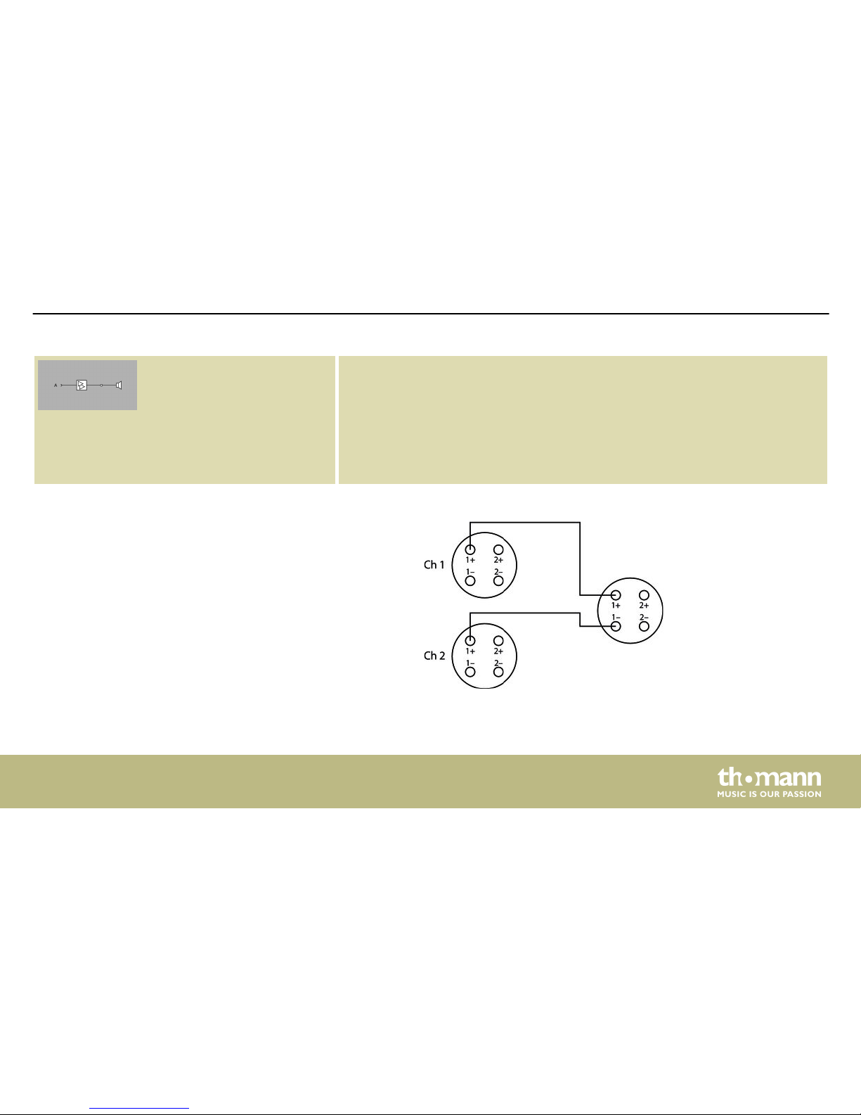
The phase of the second or fourth channel is reversed. The speaker must be
operated using a Y-adapter cable to CH1 1+ to 1+ and CH2 1+ to 1–, see gure
below.
Speaker connection in bridged
mode
Installation and starting up
E4-130, E4-250
17
Page 18

On each output of the amplier, the overall impedance resulting from the individual impe‐
dances of the connected speakers must not fall below the minimum allowable impedance of
the amp's output. If you want to connect multiple speakers to one amplier output, note the
following:
n when connecting speakers in series, the impedances add up.
n when connecting speakers in parallel, the reciprocal value of the total impedance is equal
to the sum of the reciprocal values of the individual impedances.
This means, for example with two speakers with the same impedance: In series connection,
impedance is doubled. In parallel connection, it's halved.
Detailed information on this topic can be found in our online guide ‘Speakers’
(
www.thomann.de).
The device has been designed for rack mounting in a standard 19-inch rack; it occupies two
rack units.
Total impedance
Rack mounting
Installation and starting up
power amplier
18
Page 19

5 Connections and operating elements
Front panel
Connections and operating elements
E4-130, E4-250
19
Page 20

1 [POWER]
Mains switch. Turns the device on and o. The corresponding LED lights up green when the device is turned on.
In standby mode, the LED lights red. As soon as the unit receives a signal, it switches back to normal mode and the LED
will light up green again.
2 [CH-1], [CH-2],
[CH-3], [CH-4]
Volume control for the respective channel
3 [PAR] Lights up when the respective channel pair is operated in Parallel mode.
4 [BRI] Lights up when the respective channel pair is operated in Bridged mode.
5 [SIG] Indicates the presence of an input signal.
Connections and operating elements
power amplier
20
Page 21

6 [CLIP] Lights under the following conditions:
n Channel overload.
Reduce in this case the volume until the LED goes out.
n Output short circuit.
Turn o the device immediately, correct the short circuit and turn on the device again.
7 [PRO] Lights under the following conditions:
n Three to ve seconds after switching on or o when the device is in an unstable condition.
n No speaker connected.
n The temperature of the power amp blocks has reached 85 °C.
n One or more protection circuits have been triggered, or the device is faulty.
Connections and operating elements
E4-130, E4-250
21
Page 22

Rear panel
Connections and operating elements
power amplier
22
Page 23

8 IEC chassis connector for the power supply of the device.
9 [BREAKER]
Resettable electronic fuse. If the fuse is triggered, x the cause and then push the button to reset the fuse.
10 [INPUT]
XLR chassis sockets as inputs for channels 1 to 4
11 [OUTPUT]
Speaker Twist chassis connectors for speaker outputs (1+, 2+: positive; 1, 2–: negative) for channels 1 to 4
12 Selector switch for the operating mode of the respective channel pair
n Par: Parallel mode
n Str: Stereo mode
n Bri: Bridged mode
13 [LIMIT]
Limits the output level so that the distortion is at most 5%.
Connections and operating elements
E4-130, E4-250
23
Page 24

14 [Gnd / Lift]
Ground / lift switch. If hum is caused by a ground loop, you can use this switch to disconnect the connection
between the earth pin of the device and the signal ground of the device.
15 [Stand-by ON | OFF]
On / o switch for standby function. If the standby function is enabled, the device automatically switches to standby
mode after thirty minutes without any input signal.
Connections and operating elements
power amplier
24
Page 25

6 Technical specications
Amp class AB
Input impedance
20 kΩ (balanced)
10 kΩ (unbalanced)
Output power 8 Ω, stereo 4 × 130 W RMS
4 Ω, stereo 4 × 200 W RMS
8 Ω, bridged 2 × 400 W RMS
Frequency response, ±0,5 dB 20 Hz … 20 kHz
Signal-to-noise ratio ≥ 94 dB
Total harmonic distortion (THD) ≤ 0,05 %
Crosstalk (at rated power @ 8 Ω, 1 kHz) > 64 dB
Damping factor (at rated power @ 8 Ω, 1 kHz) > 200
E4-130 (item no. 348232)
Technical specications
E4-130, E4-250
25
Page 26

Slew rate 15 V / µs
Sensitivity 1000 mV
Gain -55 dB … 30 dB
Power consumption 1500 W
Operating supply voltage
230 V 50 Hz
Dimensions (W × H × D) 482 mm × 88 mm × 408 mm
Weight 12.9 kg
Ambient conditions Temperature range 0 °C…40 °C
Relative humidity 50 %, non-condensing
Technical specications
power amplier
26
Page 27

Amp class AB
Input impedance
20 kΩ (balanced)
10 kΩ (unbalanced)
Output power 8 Ω, stereo 4 × 250 W RMS
4 Ω, stereo 4 × 400 W RMS
8 Ω, bridged 2 × 800 W RMS
Frequency response, ±0,5 dB 20 Hz … 20 kHz
Signal-to-noise ratio ≥ 94 dB
Total harmonic distortion (THD) ≤ 0,05 %
Crosstalk (at rated power @ 8 Ω, 1 kHz) > 64 dB
Damping factor (at rated power @ 8 Ω, 1 kHz) > 200
Slew rate 15 V / µs
Sensitivity 1000 mV
E4-250 (item no. 348233)
Technical specications
E4-130, E4-250
27
Page 28

Gain -52 dB … 33 dB
Power consumption 2700 W
Operating supply voltage
230 V 50 Hz
Dimensions (W × H × D) 482 mm × 88 mm × 408 mm
Weight 15.0 kg
Ambient conditions Temperature range 0 °C…40 °C
Relative humidity 50 %, non-condensing
Technical specications
power amplier
28
Page 29
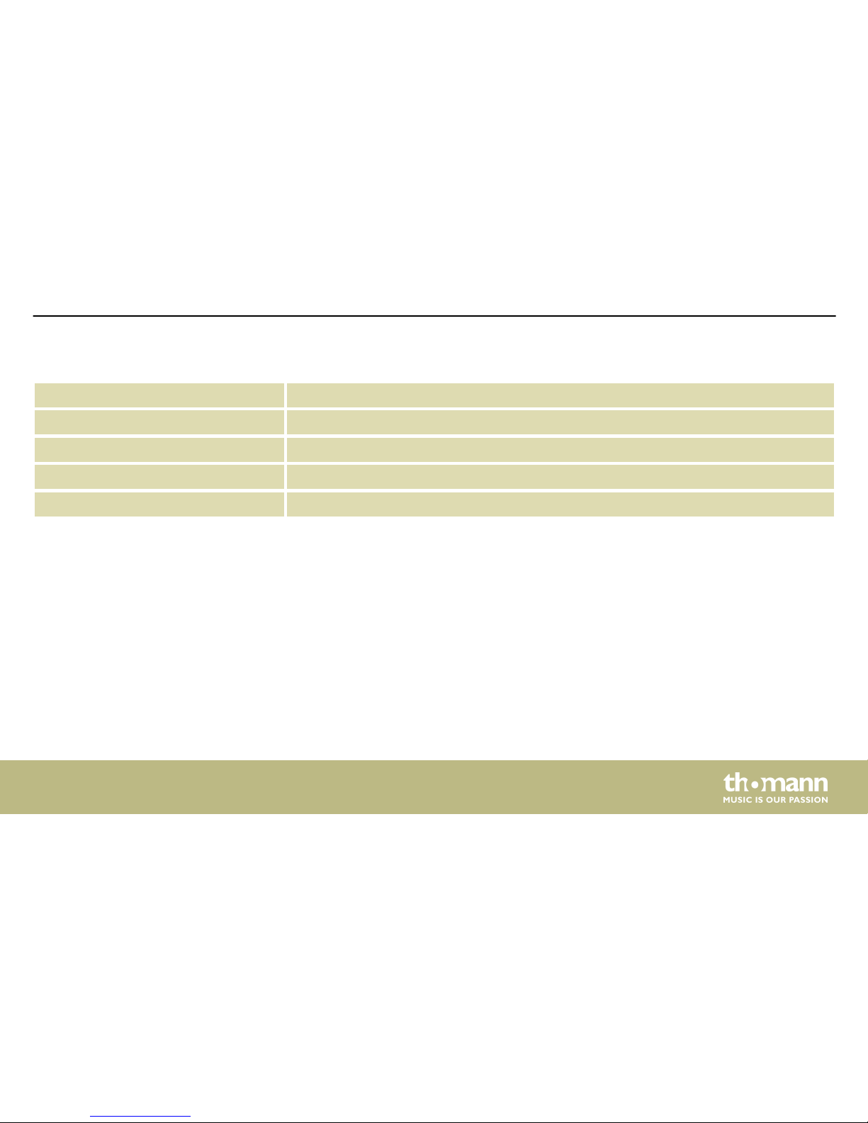
Channels 4
19" installation height 2 RU
2 Ω stable No
DSP / crossover No
Convection cooling No
Further information
Technical specications
E4-130, E4-250
29
Page 30

7 Plug and connection assignment
This chapter will help you select the right cables and plugs to connect your valuable equip‐
ment in such a way that a perfect sound experience is ensured.
Please note these advices, because especially in ‘Sound & Light’ caution is indicated: Even if a
plug ts into the socket, an incorrect connection may result in a destroyed power amp, a short
circuit or ‘just’ in poor transmission quality!
Unbalanced transmission is mainly used in semi-professional environment and in hi use.
Instrument cables with two conductors (one core plus shielding) are typical representatives of
the unbalanced transmission. One conductor is ground and shielding while the signal is trans‐
mitted through the core.
Unbalanced transmission is susceptible to electromagnetic interference, especially at low
levels, such as microphone signals and when using long cables.
In a professional environment, therefore, the balanced transmission is preferred, because this
enables an undisturbed transmission of signals over long distances. In addition to the conduc‐
tors ‘Ground’ and ‘Signal’, in a balanced transmission a second core is added. This also transfers
the signal, but phase-shifted by 180°.
Introduction
Balanced and unbalanced trans‐
mission
Plug and connection assignment
power amplier
30
Page 31

Since the interference aects both cores equally, by subtracting the phase-shifted signals, the
interfering signal is completely neutralized. The result is a pure signal without any noise inter‐
ference.
1 Ground, shielding
2 Signal (in phase, +)
3 Signal (out of phase, –)
4 Shielding on plug housing (option)
XLR plug (balanced)
Plug and connection assignment
E4-130, E4-250
31
Page 32

1 Ground, shielding
2 Signal
3 Bridged to pin 1
1, + Signal 1 (in phase)
1, – Signal 1 (out of phase)
2, + NC (not connected)
2, – NC (not connected)
XLR plug (unbalanced)
Speaker Twist connector
Plug and connection assignment
power amplier
32
Page 33

8 Cleaning
The fan grids of the device must be cleaned of any contamination, such as dust, etc. on a reg‐
ular basis. Before cleaning, switch o the device and disconnect mains-operated devices from
the mains. Only use pH-neutral, solvent-free and non-abrasive cleaning agents. Clean the unit
with a slightly damp lint-free cloth.
Fan grids
Cleaning
E4-130, E4-250
33
Page 34

9 Protecting the environment
For the transport and protective packaging, environmentally friendly materials have been
chosen that can be supplied to normal recycling.
Ensure that plastic bags, packaging, etc. are properly disposed of.
Do not just dispose of these materials with your normal household waste, but make sure that
they are collected for recycling. Please follow the notes and markings on the packaging.
This product is subject to the European Waste Electrical and Electronic Equipment Directive
(WEEE) in its currently valid version. Do not dispose with your normal household waste.
Dispose of this device through an approved waste disposal rm or through your local waste
facility. When discarding the device, comply with the rules and regulations that apply in your
country. If in doubt, consult your local waste disposal facility.
Disposal of the packaging mate‐
rial
Disposal of your old device
Protecting the environment
power amplier
34
Page 35

Page 36

Musikhaus Thomann · Hans-Thomann-Straße 1 · 96138 Burgebrach · Germany · www.thomann.de
 Loading...