

Theta Casablanca Owner's Manual

CORPORATION
Casablanca
Owner’s Manual
Digital Done Right
™

PREFACE
CONGRATULATIONS
You have just acquired the most advanced component for the control and processing of audio and video ever
to have been developed.
IMPORTANT
Save all packaging in a dry place away from fire hazards. Your Casablanca is a precision electronic
instrument and should be properly packaged any time shipment is made. In the unlikely event that you have
to return your Casablanca to the factory for service, or if you send it to us for updating, the original packaging
will best protect the unit from shipping damage.
In order to achieve the fullest flexibility and enjoyment from your Casablanca, we at Theta recommend that
you read this manual in full before connecting the unit to your audio/video system.
WARNING
United Stated law prohibits disposition of these commodities to Libya, Laos, North Korea, Cambodia or Cuba
unless otherwise authorized by the United States.
NOTE:
This equipment has been tested and found to comply with the limits for a Class B digital device, pursuant to
Part 15 of the FCC rules. These limits are designed to provide reasonable protection against harmful
interference in a residential installation. This equipment generates, uses and can radiate radio frequency
energy and, if not installed and used in accordance with the instructions, may cause harmful interference to
radio communications. However, there is no guarantee that interference will not occur in a particular
installation. If this equipment does cause harmful interference to radio and television reception, which can be
determined by turning the equipment off and on, the user is encouraged to try to correct the interference by
one or more of the following measures:
* Reorient or relocate the receiving antenna.
* Increase the separation between equipment and receiver.
* Connect the receiver into an outlet on a circuit different from that which the Casablanca is connected to.
Acknowledgments
Casa Nova is manufactured under license from Dolby Laboratories. “Dolby”, “Pro Logic”, “AC-3”, and the
double-D symbol are trademarks of Dolby Laboratories. Confidential Unpublished Works. Copyright 19921997 Dolby Laboratories, Inc. All rights reserved.
Casablanca is manufactured under license from Digital Theater Systems. Inc. US Pat. No 5,451,942 and
other worldwide patents issues pending. “DTS” and “DTS Digital Surround” are trademarks of Digital Theater
Systems, Inc. 1996 Digital Theater Systems, Inc. All rights reserved.
Casablanca is manufactured under license from SRS Labs, Inc. US Pat No 5,319,713, 5,333,201 and
7,771,295. “Circle Surround
Portions of this product manufactured under a license from Desper Products, Inc. Spatializer
the circle-in-square device are trademarks owned by Desper Products, Inc.
1996-97 Theta Digital Corporation. All rights reserved.
1996-98 Glenn Buckley. All rights reserved.
No part of this publication may be reproduced or transmitted in any form or by any means, electronic or
mechanical, for any purpose, without the express written permission of Theta Digital Corporation.
TM
” and the Circle Surround Logo are trademarks of SRS Labs, Inc. 1994-1998.
, N-2-2, and
ii

Casablanca Identification Record
This information is for your records and for future identification of the Casablanca. Please take a moment to
fill out all pertinent data now, and as upgrades and/or options are installed. Whenever upgrades and/or
changes are requested, the serial number will be required.
SERIAL NUMBER
DATE PURCHASED
DEALER’S NAME
DEALER’S ADDRESS/PHONE
INSTALLED CARDS
(Date of installation)
(Date of installation)
(Date of installation)
(Date of installation)
(Date of installation)
(Date of installation)
(Date of installation)
(Date of installation)
(Date of installation)
(Date of installation)
(Date of installation)
(Date of installation)
iii

SAFETY PRECAUTIONS
Please carefully read each item of the operating instructions and safety precautions before using this product.
Use extra care to follow the warnings written on the product itself and/or in the operating instructions. Keep
the operating instructions and safety precautions for future reference.
CAUTION: TO REDUCE THE RISK OF ELECTRICAL SHOCK, DO NOT REMOVE ANY OF THE COVER
PANELS.
NO USER-SERVICEABLE PARTS INSIDE. REFER ALL SERVICING TO QUALIFIED SERVICE
PERSONNEL ONLY.
TO PREVENT FIRE OR SHOCK HAZARD, DO NOT ALLOW LIQUIDS TO SPILL OR OBJECTS TO FALL
INTO ANY OPENINGS OF THE PRODUCT.
THIS UNIT IS SUPPLIED WITH A 3 PIN GROUNDED AC PLUG. ALWAYS INSERT THE AC PLUG INTO A
GROUNDED OUTLET. DO NOT REMOVE THE GROUND PIN OR DISABLE THE GROUND FOR ANY
PURPOSE.
BEFORE MAKING ANY CONNECTIONS TO THE CASABLANCA, FIRST TURN OFF THE POWER AND
THEN DISCONNECT THE AC POWER CORD.
WHEN INSTALLING THE CASABLANCA IN YOUR SYSTEM, MAKE CERTAIN TO ALLOW A MINIMUM
OF ½ INCH OF VENTILATION ON EACH SIDE OF THE UNIT. ALSO ALLOW AT LEAST 1½ INCH OF
VENTILATION SPACE ABOVE THE UNIT. IMPROPER VENTILATION OF THE UNIT MAY CAUSE
OVERHEATING, WHICH MAY DAMAGE THE UNIT AND CAUSE A FIRE. PLACE THE UNIT ON A SOLID
SURFACE ONLY. I.E. NOT ON CARPET, ETC.
DO NOT PLACE THE CASABLANCA NEAR HEAT SOURCES SUCH AS DIRECT SUNLIGHT, STOVES,
HEAT REGISTERS, RADIATORS OR OTHER HEAT PRODUCING EQUIPMENT.
TO PREVENT DAMAGE TO THE ANALOG OUTPUT CIRCUITRY, BE CERTAIN NOT TO SHORT THE
OUTPUT SIGNAL PIN(S) TO GROUND. ENSURE THAT YOUR AUDIO OUTPUT CABLES DO NOT HAVE
ANY INTERNAL SHORTS BEFORE CONNECTING THEM TO THE CASABLANCA.
IF REPLACEMENT OF THE AC LINE FUSE BECOMES NECESSARY, REPLACE ONLY WITH SAME
VALUE AND TYPE OF FUSE. NEVER BYPASS THE FUSE.
IF THE AC CORD BECOMES DAMAGED, DO NOT USE IT. IMMEDIATELY REPLACE IT WITH A NEW
ONE OF THE SAME OR BETTER RATING.
AFTER MARKET and THIRD PARTY MODIFICATIONS
Please note that any after market and/or third party modifications will void the warranty. In the case of
changing the feet on a unit, in order to prevent any damage (which will also not be covered under warranty),
please verify that the screws being used to secure non Theta feet do not screw any deeper into the chassis
than the original ones. The original screw is 10-32 by 3/8 and goes into the chassis 1/5 of an inch.
iv

Table of Contents
PREFACE ...........................................................................................................................................................ii
Casablanca Identification Record ................................................................................................................... iii
SAFETY PRECAUTIONS ............................................................................................................................. iv
List of Figures ................................................................................................................................................. vi
List of Tables ..................................................................................................................................................vi
INTRODUCTION................................................................................................................................................ 1
IMPORTANT NOTICE.................................................................................................................................... 2
Reference Manual Conventions ..................................................................................................................... 2
Glossary of Terms and Abbreviations ............................................................................................................ 3
Block Diagram - Input and Surround Processing Sections ............................................................................ 4
Block Diagram - DAC and Analog Out Sections............................................................................................. 5
Front Panel Layout ......................................................................................................................................... 6
Rear Panel Layout .......................................................................................................................................... 7
FRONT PANEL OPERATIONS ......................................................................................................................... 9
Main Menu ...................................................................................................................................................... 9
A-D Button .................................................................................................................................................... 10
Priority Switching .......................................................................................................................................... 10
Mode Function .............................................................................................................................................. 11
Tape Out Function ........................................................................................................................................ 14
Standard Tape Out Configuration ............................................................................................................. 14
Optional Upgrade Tape Out Configuration ............................................................................................... 14
Set-Up Function............................................................................................................................................ 15
Set-Up - Speaker Configuration ................................................................................................................ 16
Set-Up - Speaker Levels ........................................................................................................................... 18
Set-Up - Speaker Delays .......................................................................................................................... 19
Set-Up - Analog Input Levels .................................................................................................................... 20
Set-Up - Input Names ............................................................................................................................... 21
Set-Up - Miscellaneous ............................................................................................................................. 22
Set-Up - (Second Page): Dolby Digital...................................................................................................... 23
Balance Function .......................................................................................................................................... 24
REMOTE CONTROL ....................................................................................................................................... 25
Remote Control Layout................................................................................................................................. 26
Remote Control Operations .......................................................................................................................... 27
Input Select Menu and Non Menu Functions................................................................................................ 27
Status Display............................................................................................................................................... 28
Mode Function .............................................................................................................................................. 29
Tape Out Function ........................................................................................................................................ 30
Set-Up Function............................................................................................................................................ 31
Set-Up - Speaker Configuration ................................................................................................................ 32
Set-Up - Speaker Levels ........................................................................................................................... 33
Set-Up - Speaker Delays .......................................................................................................................... 34
Set-Up - Analog Input Levels .................................................................................................................... 35
Set-Up - Input Names ............................................................................................................................... 36
Set-Up - Miscellaneous ............................................................................................................................. 37
Set-Up - (Second Page): Dolby Digital...................................................................................................... 38
Balance Function .......................................................................................................................................... 39
APPENDIXES .................................................................................................................................................. 40
Appendix A Troubleshooting Guide........................................................................................................ 41
Appendix B Wiring Diagrams and Speaker Placement Guides ............................................................. 42
Input and Tape Out Connections ..................................................................................................... 42
Rear Panel Remote and Main power Jacks .................................................................................... 42
Six Channel Single-Ended Output Wiring Diagram ......................................................................... 43
Six Channel Balanced Output Wiring Diagram................................................................................ 44
Nine Channel Balanced Output Wiring Diagram ............................................................................. 45
Appendix C Factory Settings and Blank Setting Charts ......................................................................... 46
Appendix D Remote Extender Jack Technical Description and Protocol............................................... 47
Appendix E Specifications...................................................................................................................... 48
Limited Warranty Terms and Conditions ...................................................................................................... 49
v

List of Figures
Figure 1 - Block Diagram of Input and Surround Processing Sections ..............................................................4
Figure 2 - Block Diagram of DAC and Analog Outputs ...................................................................................... 5
Figure 3 - Front Panel Layout............................................................................................................................. 6
Figure 4 - Rear Panel Layout ............................................................................................................................. 7
Figure 5 - Front Panel Display of the MAIN Menu.............................................................................................. 9
Figure 6 - Front Panel Display of the MODE Menu - First Page ...................................................................... 11
Figure 7 - Front Panel Display of the MODE Menu - Second Page ................................................................. 12
Figure 8 - Front Panel Display of the TAPE OUT Menu .................................................................................. 14
Figure 9 - Front Panel Display of the SET-UP Menu - First Page.................................................................... 15
Figure 10 - Front Panel Display of the SET-UP Menu - Second Page............................................................. 15
Figure 11 - Front Panel Display of the SET-UP: Speaker Configuration Sub Menu ........................................ 16
Figure 12 - Front Panel Display of the SET-UP: Speaker Levels Sub Menu ................................................... 18
Figure 13 - Front Panel Display of the SET-UP: Speaker Delays Sub Menu................................................... 19
Figure 14 - Rear Delay Settings ....................................................................................................................... 19
Figure 15 - Front Panel Display of the SET-UP: Analog Input Levels Sub Menu ............................................ 20
Figure 16 - Front Panel Display of the SET-UP: In Name Sub Menu .............................................................. 21
Figure 17 - Front Panel Display of the SET-UP: Misc Sub Menu..................................................................... 22
Figure 18 - Front Panel Display of the SET-UP: (Second Page): Dolby Digital Sub Menu .............................. 23
Figure 19 - Front Panel Display of the Balance Menu - First Page .................................................................. 24
Figure 20 - Front Panel Display of the Balance Menu - Second Page............................................................. 24
Figure 21 - Remote Control Layout.................................................................................................................. 26
Figure 22 - Video Monitor Display of the INPUT Menu .................................................................................... 27
Figure 23 - Video Monitor Display of the STATUS Display .............................................................................. 28
Figure 24 - Video Monitor Display of the MODE Menu - First Page.................................................................29
Figure 25 - Video Monitor Display of the MODE Menu - Second Page ........................................................... 29
Figure 26 - Video Monitor Display of the Tape Out Menu ................................................................................ 30
Figure 27 - Video Monitor Display of the SET-UP Menu - First Page .............................................................. 31
Figure 28 - Video Monitor Display of the SET-UP Menu - Second Page ......................................................... 31
Figure 29 - Video Monitor Display of the SET-UP: Speaker Configuration Sub Menu .................................... 32
Figure 30 - Video Monitor Display of the SET-UP: Speaker Levels Sub Menu................................................ 33
Figure 31 - Video Monitor Display of the SET-UP: Speaker Delays Sub Menu ............................................... 34
Figure 32 - Video Monitor Display of the SET-UP: Analog Input Levels Sub Menu ......................................... 35
Figure 33 - Video Monitor Display of the SET-UP: Input Names Sub Menu .................................................... 36
Figure 34 - Video Monitor Display of the SET-UP: Miscellaneous Sub Menu.................................................. 37
Figure 35 - Video Monitor Display of the SET-UP: (Second Page): Dolby Digital Sub Menu .......................... 38
Figure 36 - Video Monitor Display of the Balance Menu - First Page ..............................................................39
Figure 37 - Video Monitor Display of the Balance Menu - Second Page ......................................................... 39
Figure 38 - Examples of Input and Tape Out Connections .............................................................................. 42
Figure 39 - Recommended Wiring Scheme Using the Six Channel Single-Ended Output Card ..................... 43
Figure 40 - Recommended Speaker Placement for Six Channel Configuration.............................................. 43
Figure 41 - Recommended W iring Scheme Using Six Balanced Channels .................................................... 44
Figure 42 - Recommended W iring Scheme Using Nine Balanced Channels .................................................. 45
Figure 43 - Recommended Speaker Placement for Nine Channel Configuration ........................................... 45
List of Tables
Table 1 - Glossary of Terms and Abbreviations................................................................................................. 3
Table 2 - Priority Switching Defaults ................................................................................................................ 10
Table 3 - Available Configuration Settings for Each Speaker .......................................................................... 16
Table 4 - Source to Output Routing for Speaker Level Configuration..............................................................18
Table 5 - Available Video Source Names ....................................................................................................... 21
Table 6 - Available Audio Source Names ........................................................................................................ 21
vi

INTRODUCTION
Welcome to a new world of possibilities. Casablanca is by far the most advanced surround sound
processor/home theater controller available today. It offers the advantages of Theta’s legendary mastery in
digital signal processing and sound quality unapproachable by any other equipment.
Getting to know your Casablanca
Despite Casablanca’s great technical sophistication, we believe in making it as easy as possible for you to
use. We think you’ll enjoy the intuitive way the Casablanca works. Rather than offer a frustrating
bewilderment of little used functions in constant view, vying for your attention, Casablanca is structured
systematically by function.
The “user interface” is based on simple logic. For example, when a function button is pressed, you can make
changes within its menu(s) and press the same function button again to store the changes and exit that
function. (The same button that got you in gets you back out). Also, when in a function menu or sub-menu,
other features and functions will not be accessible, as they have no direct relation to the function being edited.
This Casablanca has been put through a rigorous and unique testing procedure that insures that it will last for
many years with minimal service requirements. This procedure includes the following:
• All assembled circuit boards are given a thorough visual inspection and are then tested in a bench-
reference Casablanca.
• The tested assembled circuit boards are then installed in a new Casablanca and the whole unit is
tested for every function and parameter.
• The unit is put on a burn-in torture rack for 100 hours to test for any possible component failures.
• The Casablanca is tested on an audio analyzer for all pertinent parameters.
• The Casablanca is put through a final bench test wherein every possible feature, mode and parameter
is checked.
• The unit has all remaining chassis components installed and then undergoes a complete visual
inspection, which assures that all Casablanca’s meet visual specifications.
Burn In Time
This unit has a break in period of about 1 week during which continuous improvement in sound quality will be
observed. It is recommended that music be played continuously through the unit during this time, to expedite
the break in period.
1

IMPORTANT NOTICE
I. Due to the computer-based circuitry used in Theta products, it is imperative that the Casablanca be
connected to a ground via its three wire AC power cord. It is important that the AC power outlet,
which the Casablanca is plugged into, is actually grounded. Failure to do so will severely
compromise the performance, reliability and safety of use of the Casablanca.
II. It is also important to prevent contact with static electricity when connecting other components and
cables to the Casablanca. When connecting cables, simply place one hand on top of the
Casablanca and then grasp the metal “barrel” of the cable with the other hand and plug (unplug) the
cable into (from) the appropriate jack on the Casablanca.
III. The Casablanca, as with all electronic equipment, is susceptible to static discharges. Resetting the
unit may be required if anomalies occur after receiving a static discharge. In this case, put the unit in
standby and turn off the rear panel power switch for 1 minute, then turn it on again.
IV. Ventilation is an important issue when placing the Casablanca in a system. Make certain that the
Casablanca is placed in a well ventilated area or rack unit.
V. Please take note that some powerline conditioners defeat the AC power ground on their outlets. If
the intention is to plug the Casablanca into a line conditioner, check with your dealer to make certain
that the particular conditioner that is intended for use DOES NOT DEFEAT THE AC GROUND on its
AC outlets.
VI. DO NOT remove any cover panels from the Casablanca, as there are no user serviceable
components inside. Refer servicing and updating to qualified service personnel only.
VII. The Casablanca can be susceptible to excessive RF. Shorting plugs in all unused inputs will improve
the sound quality and may reduce the susceptibility to RF induced anomalies.
Reference Manual Conventions
For clarity purposes, references to buttons, LED’s and display parameters will be shown in bold capital letters.
All functions to be performed from, and in reference to the front panel of the Casablanca will be found in the
front section of this manual, whereas all functions to be performed using the hand held remote and/or viewed
on a video monitor will be found in the back, or last part of this manual.
2
Glossary of Terms and Abbreviations
TERM DEFINITION
AES/EBU (Audio Engineering Society) /
(European Broadcasters Union)
Analog-to-Digital Converter A device that converts analog signals into a digital
Balanced Audio Signals Signals that are carried on three-conductor cables,
dB Decibel, a relative unit of loudness.
Dolby 3 Stereo The Dolby 3 Stereo mode reproduces sound using
Digital-to-Analog Converter A device that converts digital signals into an analog
Hz (Hertz) A unit of frequency.
IR Infrared. A method of wireless transmission of data.
LFE Low Frequency Effect. Commonly a discrete audio
mS milliSecond, or 1\1000 of a second.
Oversampling The process of taking more samples than is required
Phantom Center Mode The Phantom setting for the center speaker redirects
Phantom Surround Mode The Phantom setting for the surround speakers is
Sampling Rate The rate at which an analog (real world) signal is
S/PDIF Interface (Sony/Phillips Digital
Interface format)
TRS Tip, Ring, Sleeve. Names of the 3 connecting
Unbalanced Audio Signals (AKA single-ended) Signals that are carried on two-conductor cables,
Table 1 - Glossary of Terms and Abbreviations
A three wire balanced digital audio standard. This
interface uses a 3-pin XLR type connector and
allows for data communication between digital audio
equipment.
format. Once encoded, all audio is stored or
processed as a series of numbers rather than as the
audio itself.
with two of the conductors carrying the same signal
180° out of phase and the third as ground. Balanced
connections usually cost more than unbalanced
connections, but are less susceptible to picking up
hum and prevent interference with low-level signals.
only the 3 front channels, and is intended to be used
either before surround speakers are installed, or for
programs that might benefit from deriving a center
channel output, but where the quality of the surround
output is unsatisfactory.
format.
track designated for a sub woofer.
in order to more accurately reconstruct a digitized
signal for playback in the analog domain.
the center channel signal equally to the front left and
right outputs, thus creating an illusion of a center
speaker. It is to be used when a center speaker is
not present.
intended to be used when no surround speakers are
present in the system. With this setting active, the
surround information is added to the front channels.
If the current mode is Dolby Pro Logic, the
Casablanca will automatically decode in Dolby 3
Stereo.
converted into digital numeric values.
A digital audio interconnection standard, developed
jointly by Sony and Phillips.
elements of a stereo phono jack or plug.
one “hot”, or signal, and one ground.
3
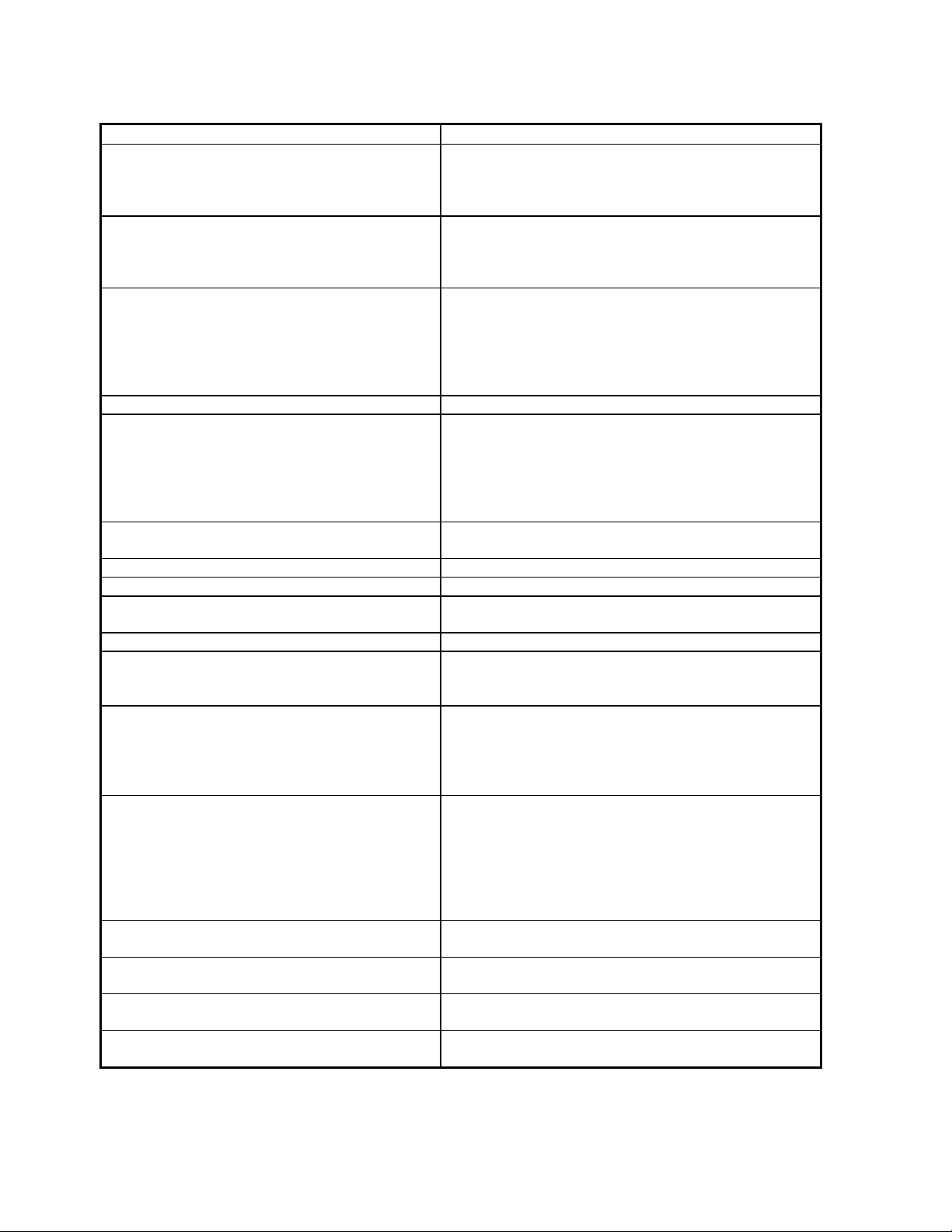
Block Diagram - Input and Surround Processing Sections
Figure 1 - Block Diagram of Input and Surround Processing Sections
4
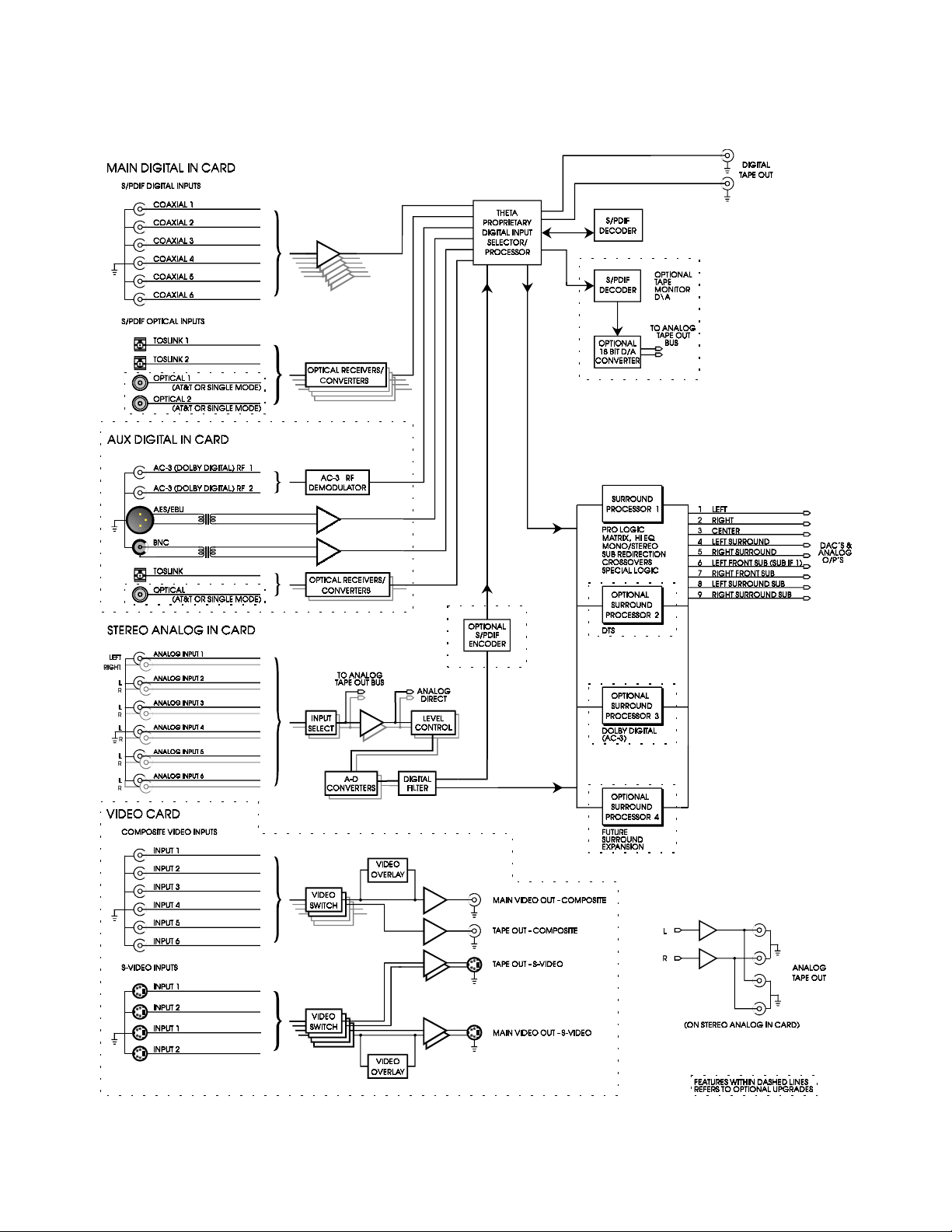
Block Diagram - DAC and Analog Out Sections
Figure 2 - Block Diagram of DAC and Analog Outputs
5
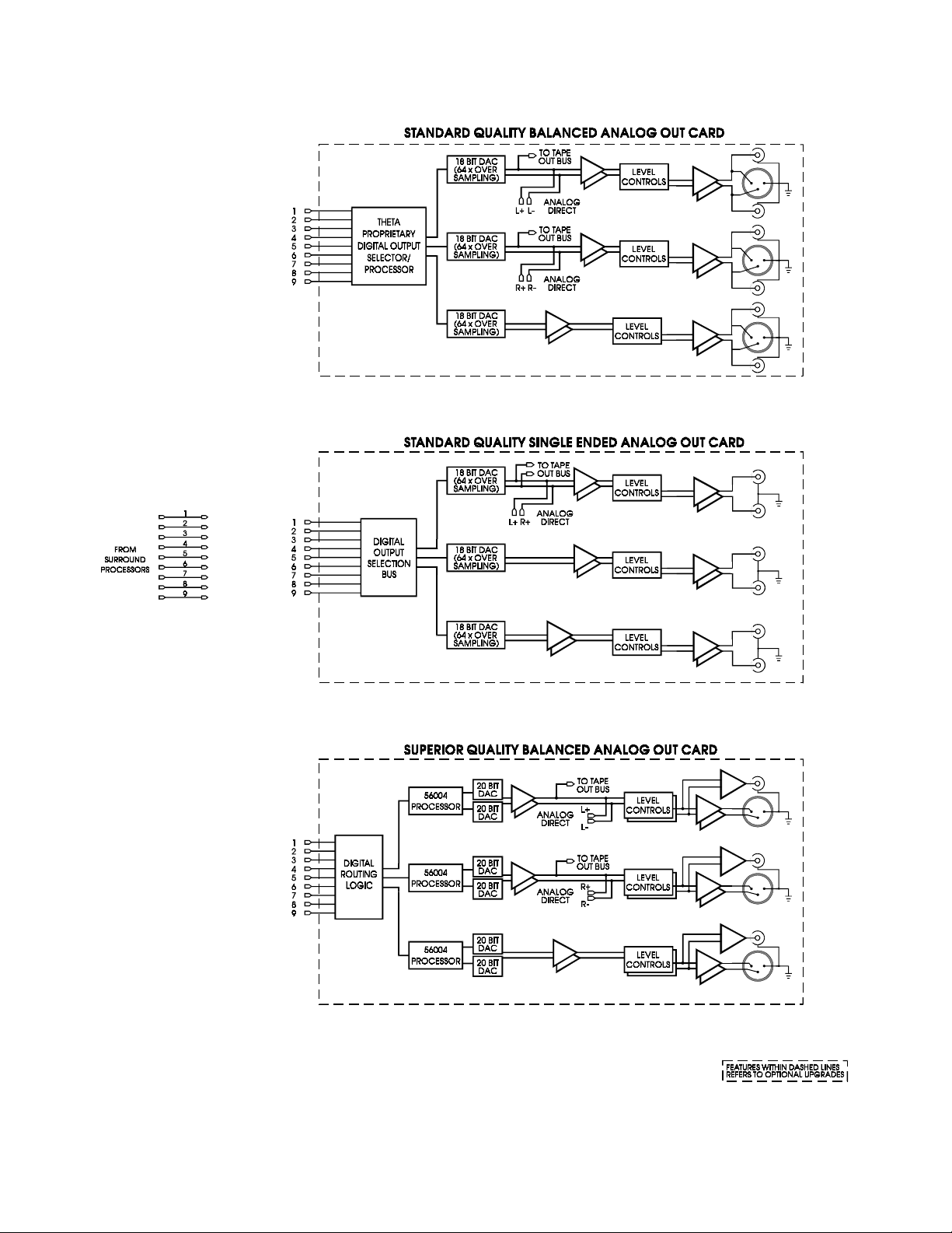
Front Panel Layout
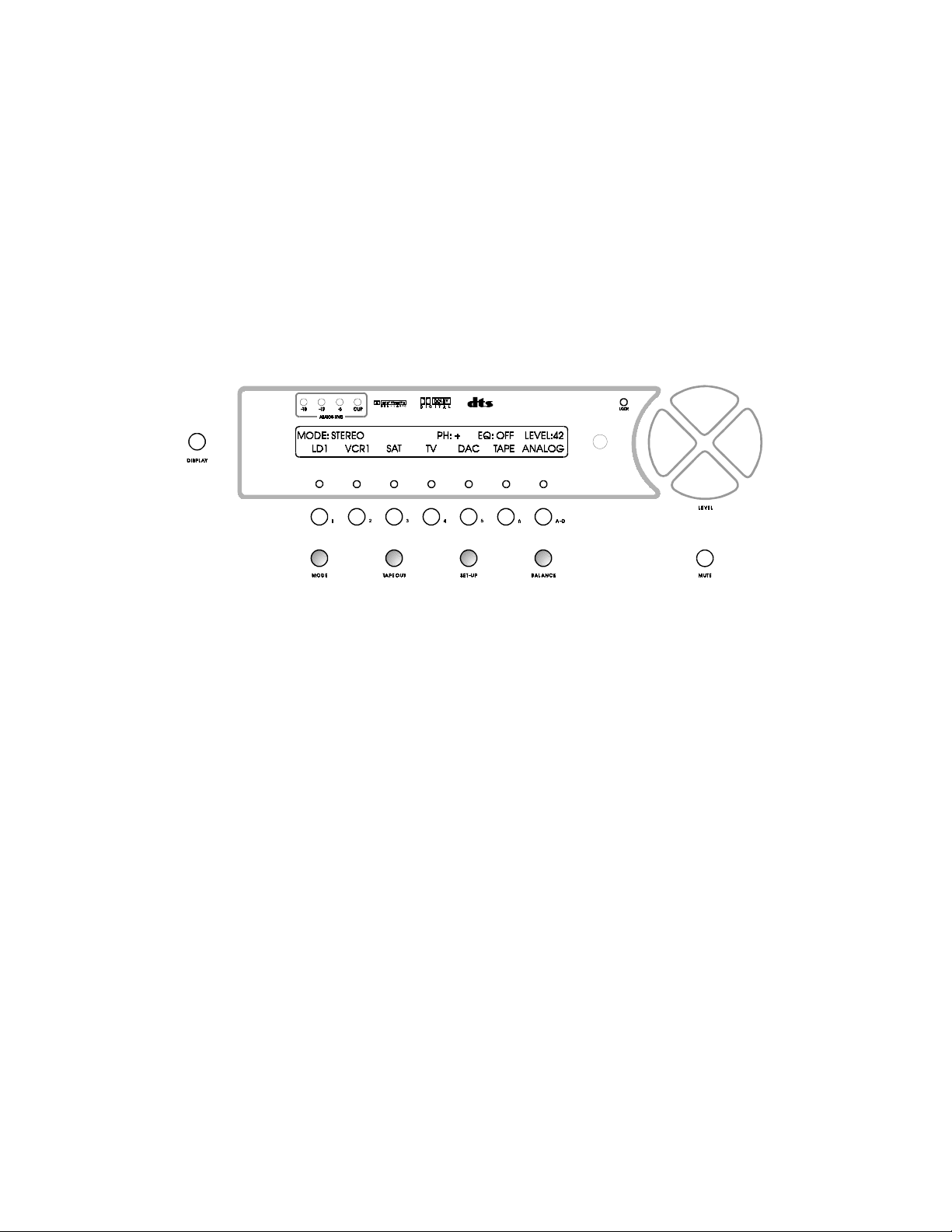
Figure 3 - Front Panel Layout
1. 40 character by 2 row amber or green back lit liquid crystal display (
DISPLAY
2.
POWER
3.
POWER
4.
exit the standby mode. The LCD will display the
Casablanca into standby mode and the LED above the front panel
REMOTE
5.
6. Buttons 1 through 6. Used to select a desired input on the
menu.
MODE
7.
TAPE OUT
8.
SET-UP
9.
the display & remote power jack time-out delays, selecting between NTSC and PAL video sources and accessing
additional Dolby Digital parameters.
BALANCE
10.
A-D
11.
will depend on the current
MUTE
12.
ANALOG LEVEL
13.
button. Press repeatedly to change front panel LCD brightness between off, low, medium and high.
LED. Lights when the Casablanca is in standby mode.
button. After the rear panel
button. Activates/deactivates the
button. Activates the
button. Used for routing audio and video
button. Used for setting speaker configurations/levels/delays, analog input levels, naming inputs, setting
button. Sets a temporary balance configuration to adjust for unique program or room characteristics.
button. Activates either the analog, digital or RF input jack for the selected input channel. Available options
button. Mutes/unmutes all audio outputs with the exception of the
display. Shows input level, in dB, of currently selected analog input.
MODE
MODE
MAIN POWER
REMOTE POWER
select menus for the currently selected input.
, and RF will only be an option if the optional Digital Input board is installed.
switch is turned on press the front panel
MAIN
INPUT
signals to the
LCD).
POWER
menu. Pressing this button again will place the
POWER
jack on the rear panel.
MAIN MENU
button will light.
, or parameter to change when in a sub
TAPE OUT
TAPE OUT
jacks.
jacks.
button to
Dolby Pro Logic
14.
also installed, The
Dolby Digital
15.
DTS
16.
17.
18.
19.
20.1 through 6 LED indicators. Light when buttons 1 through 6 are selected.
indicator. Lights when the DTS feature is installed. It will go out when the display is turned off.
LOCK
light. Lights when a digital source is detected on a selected input.
LEVEL LEFT
selected, adjusts EQ parameter when the
LEVEL UP
in most edit modes, and shifts
indicator. Lights when the Dolby Pro Logic feature is installed only. If Dolby Digital (AC-3) is
Dolby Pro Logic
indicator. Lights when Dolby Digital is installed. It will go out when the display is turned off.
RIGHT
and
and
DOWN
buttons. Shifts audio balance to the left and right when the
buttons. Increases/decreases master volume. Also used to increment/decrement values
indicator will not be lit. It will go out when the display is turned off.
MAIN MENU
FRONT/REAR
audio balance in
is active and adjusts the slope value in the
BALANCE
6
mode.
BALANCE
SET-UP
function is
menu.

Rear Panel Layout
Figure 4 - Rear Panel Layout
Main Power Switch.
1.
this be left ON at all times during regular use with the exception of whenever cables are connected/disconnected
or when the unit is not going to be used for an extended period of time.
Master power switch. Disconnects AC to all circuits past the switch. It is recommended that
AC Power
2.
Remote Power
3.
again.
Main Power 1
4.
Main Power 2
5.
the time parameter value that is stored in the
when the front panel
Main Power 3
6.
represents the time parameter value that is stored in the
deactivated when the front panel
Remote Control Extender
7.
stereo phone jack. Please refer to Appendix D for technical details.
Video
8.
switched with corresponding audio inputs and fed to the main video output. Four S-Video inputs, corresponding to
the first four audio inputs only, are provided for the same functionality as the composite inputs, except in the SVideo format. Video inputs are routed to the video tape output jack through the
input signals can be present at the S-Video
Main Digital Input
9.
S/PDIF format at 32K, 44.1K or 48KHz sampling rates. There are two open spaces provided for optional AT&T
and/or Theta Single Mode Laserlinque optical input modules. There are two RCA digital Tape Out connectors on
this card who’s source can be selected in the
connector: 3 wire, IEC 320 connector with an EMI filter.
jack. Activated/deactivated when associated front panel or remote button is pressed/pressed
jack. Activated/deactivated when front panel
jack. Activated when front panel
POWER
jack. Activated when front panel
card. This optional card, necessary for on-screen display, provides six composite RCA inputs that are
card. Six Coaxial (RCA) and two TosLink inputs are provided for digital audio signals in the
button is pressed again (putting the Casablanca in Standby mode).
POWER
jack. An externally mounted (remote) Infrared (IR) receiver plugs into this miniature
button is pressed again (putting the Casablanca in Standby mode).
POWER
SET-UP: MISC
POWER
Main
and/or
TAPE OUT
POWER
button is pressed once, plus x seconds. X represents
button is pressed once, plus two times x seconds.
SET-UP: MISC
Tape
outputs.
menu.
button is pressed/pressed again.
sub menu,
RPWR
feature. This jack is deactivated
sub menu,
RPWR
TAPE OUT
feature. This jack is
button. Only S-Video
X
Auxiliary Digital Input
10.
(balanced XLR) input , one BNC and one TosLink input. Additionally there is one space provided for an optional
AT&T or Theta Single Mode optical input.
Analog Input
11.
laserdisc, CD and DAT players, phono preamplifiers, external D/A converters, Tape decks, AM/FM tuners, etc.
There are two pairs of analog tape outs for recording purposes.
card. Six stereo RCA inputs are provided for any line level analog output devices such as VCR’s,
card. This optional card provides two RCA Dolby Digital (AC-3) RF inputs, one AES/EBU
7

12. First
Analog Output
channel (L & R) superior quality balanced card loaded in this slot. Configured as a surround processor,
this slot could contain one of the following: A six channel standard quality single ended D/A card (left,
right, center, sub, left surround and right surround) or a three channel balanced card (left, right and
center). A balanced card can be either standard or superior quality. All balanced cards also have single
ended outputs; the standard card has a plus and minus single ended output for each channel whereas
the superior quality balanced card is equipped with one gold plated single ended output jack on each
channel.
card. Configured as a 2 channel D/A converter/preamp there would be a 2
13. Second
standard quality balanced card or a three channel superior quality balanced card. If only two analog
output cards are installed, this slot would contain outputs for sub, left surround and right surround
channels. If three analog output cards are installed, this second slot would contain outputs for left front
sub, left surround and right surround channels.
14. Third
card or a three channel superior quality balanced card, however, it must be the same quality as the
second card. This third slot accommodates additional sub woofers (right front sub, left surround sub
and right surround sub). Figure 4 represents this configuration in standard quality.
Analog Output
Analog Output
card. This slot could contain one of the following options: a three channel
card. This slot could contain either a three channel standard quality balanced
8
FRONT PANEL OPERATIONS
This section describes the functionality of each button on the Casablanca’s front panel only. For remote
functionality descriptions, please refer to the section entitled
manual. Descriptions for front panel buttons/functionality not covered in this section can be found in the
preceding
FRONT PANEL LAYOUT
section.
REMOTE CONTROL OPERATIONS
Main Menu
later in this
When the Casablanca is first powered up via the
default standby mode. Pressing the
start-up routine and then the
turns off. This display will be on all of the time during normal operation and will change only when one of the
function buttons (shown shaded in figure 5) is pressed. The
example only and will most likely differ from the user’s set up.
MAIN MENU
POWER
, shown in figure 5 below. As this menu appears, the
MAIN POWER
button on the front panel will result in the LCD displaying the
* * *
switch on the back panel, it will be in the
POWER
INPUT NAMES
shown in this figure are for
LED
Figure 5 - Front Panel Display of the MAIN Menu
Pressing the
from 0 to 73, relative maximum.
Pressing the
low pass shelf EQ that, at 2KHz, drops by 1.5dB when the parameter value is set at 1, 3dB when set at 2,
6dB when set at 3, and 9dB when set at 4. Being a shelf EQ, the roll off amplitude never drops significantly
below the specified dB value. The EQ is active in all modes except Analog Direct and the front left/right
speakers in Analog Matrix modes. It is designed to roll off excess brightness in different program material.
LEVEL UP/DOWN
LEVEL LEFT/RIGHT
buttons will adjust the master volume for all speakers. This value ranges
buttons will adjust the EQ setting between
OFF, 1, 2, 3
and 4. This is a
MUTE
The
feature is enabled, the
either the
is set to
The
The
off, the red Dolby Pro Logic, Dolby Digital and DTS displays go off, if applicable.
Buttons 1 through 6 are used to select a desired input, or audio source. Each has an LED above it, which will
light when the respective input button is pressed. Note that only inputs 1 through 4 have S-video input jacks
and only inputs 1 and 2 have Dolby Digital (
Pressing the
either analog or digital, whichever corresponds to the signal format being sent to the currently selected input.
See page 10 for additional information on the
Pressing the
value of + means that the audio output phase is at 0° and - (minus) is at 180° out of phase.
button will toggle the audio on and off in all speakers each time it is pressed. When the mute
LEVEL
MUTE
button is pressed again or the
DIGITAL
MUTE
DISPLAY
, the Casablanca will remain muted until it locks on to a valid signal on the selected input.
feature is active in all menus.
button will toggle the LCD brightness between off, low, medium and high. When the display is
A-D
button will toggle the currently selected input between
PHASE
button on the remote when the
value will be replaced with the word
LEVEL UP
AC-3 RF
A-D
button.
) input jacks.
or
MAIN
menu is active will change the
9
MUTING
DOWN
, which will remain displayed until
buttons are pressed. If the
ANALOG
and
DIGITAL
PHASE
A-D
button
. Select
value. A
A-D Button
The primary use of the
channel. For example, Input channel # 1 has several physical input jacks on the rear panel, all of which
accept
A-D
the
Caution
only into an analog input jack. Damage, not covered under warranty, can occur if an analog signal is applied
to a digital input. Additionally, please ensure that a video plug is not inadvertently inserted into a digital audio
jack and visa versa, otherwise, the Casablanca will cease to respond.
Some devices such as LD players feature both analog and digital audio outputs. To avoid rewiring the LD
player outputs to the Casablanca inputs when changing between laser disks with analog only audio tracks, it
is advisable to connect both the analog and digital outputs of the LD player, if featured, to both the
Casablanca’s analog and digital inputs (use the same input channel number). In this way, if the Casablanca’s
LD1
input is set to
A-D
button will instantly reconfigure the Casablanca to play the analog tracks.
When using modes that utilize digital formats only, such as Dolby Digital, DTS, etc., the
deactivated except:
1) In the case of selecting the
digital Dolby Digital signal present on the same input channel. Please refer to page 11 for additional
information on using the
2) When the
mode is only temporary, and not stored. In this case, if the stored
by via the
will become active as soon as the
an analog or a digital signal. When appropriate signals are applied to both of these, pressing
either
button simply selects one of them and ignores the other(s).
: Please take special care to insert only a digital signal into a digital input jack and an analog signal
MODE
A-D
button, the display will show
A-D
button is to select either the analog or digital input jack for a specific input
DIGITAL
is not stored. If the auto-detect feature automatically changes the
and an LD being played contains only analog audio tracks, simply pressing the
AC-3 RF
AC-3 RF
jacks for the Dolby Digital mode when there is both an RF and
jacks with the Dolby Digital mode.
MODE
MODE
ANALOG
reverts back to the stored
and the analog inputs of the current input channel
allows the selection of
MODE
(approximately 15 seconds).
MODE
A-D
button is
, the detected
ANALOG
The Analog Direct and Analog Matrix modes accept an analog input only. Therefore,
in the LCD above the
A-D
button at all times when in either of these modes, thus deactivating the
ANALOG
is displayed
A-D
button.
Priority Switching
The Casablanca’s inputs can support virtually every digital audio data format used in today’s technology.
Since it is most unlikely that one input number will require more than one digital format, some of the input
jacks share the same input channel number. For example, an AES/EBU (balanced) XLR, a glass optical, a
TosLink, and an RCA jack are all assigned to input # 1.
If a digital signal were present at more than one input jack with the same input channel assigned to it, the
Casablanca will automatically select one of them according to a pre-determined priority, since two input
signals cannot share the same channel. This is called
Each input channel has different input jacks assigned to it, as indicated by the channel number next to each
digital input on the rear panel. Table 2 shows the entire priority switching scheme.
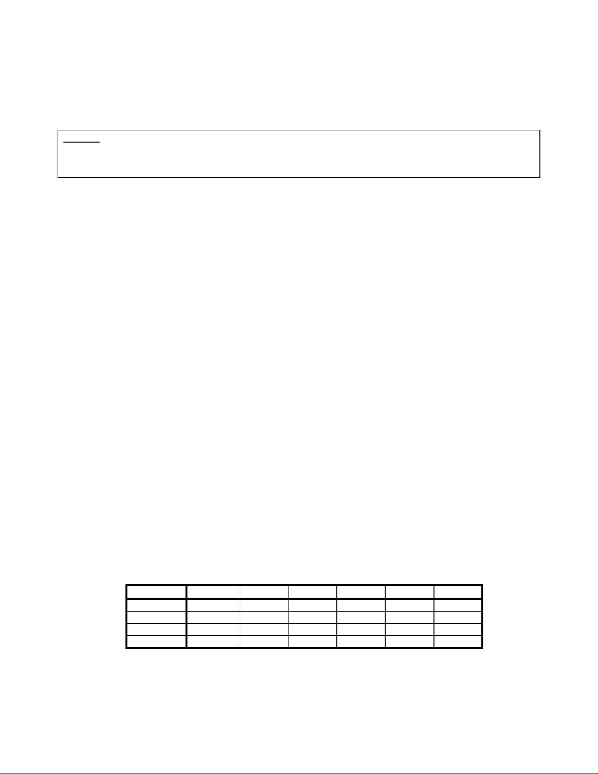
PRIORITY INPUT 1 INPUT 2 INPUT 3 INPUT 4 INPUT 5 INPUT 6
1 AES/EBU BNC TosLink Optical RCA RCA
2 RCA RCA RCA RCA - 3 TosLink TosLink - - - 4 Optical Optical - - - -
Table 2 - Priority Switching Defaults
Priority Switching
.
10
Mode Function
Pressing the
page consists of 6 different signal ‘processing’ modes, one of which can be selected and applied to the
currently selected input. The menu title “
displayed in the lower right corner of the LCD indicating that there are more modes to select from on the next
page. Pressing the
second page the menu title “
below it. This indicates that pressing the
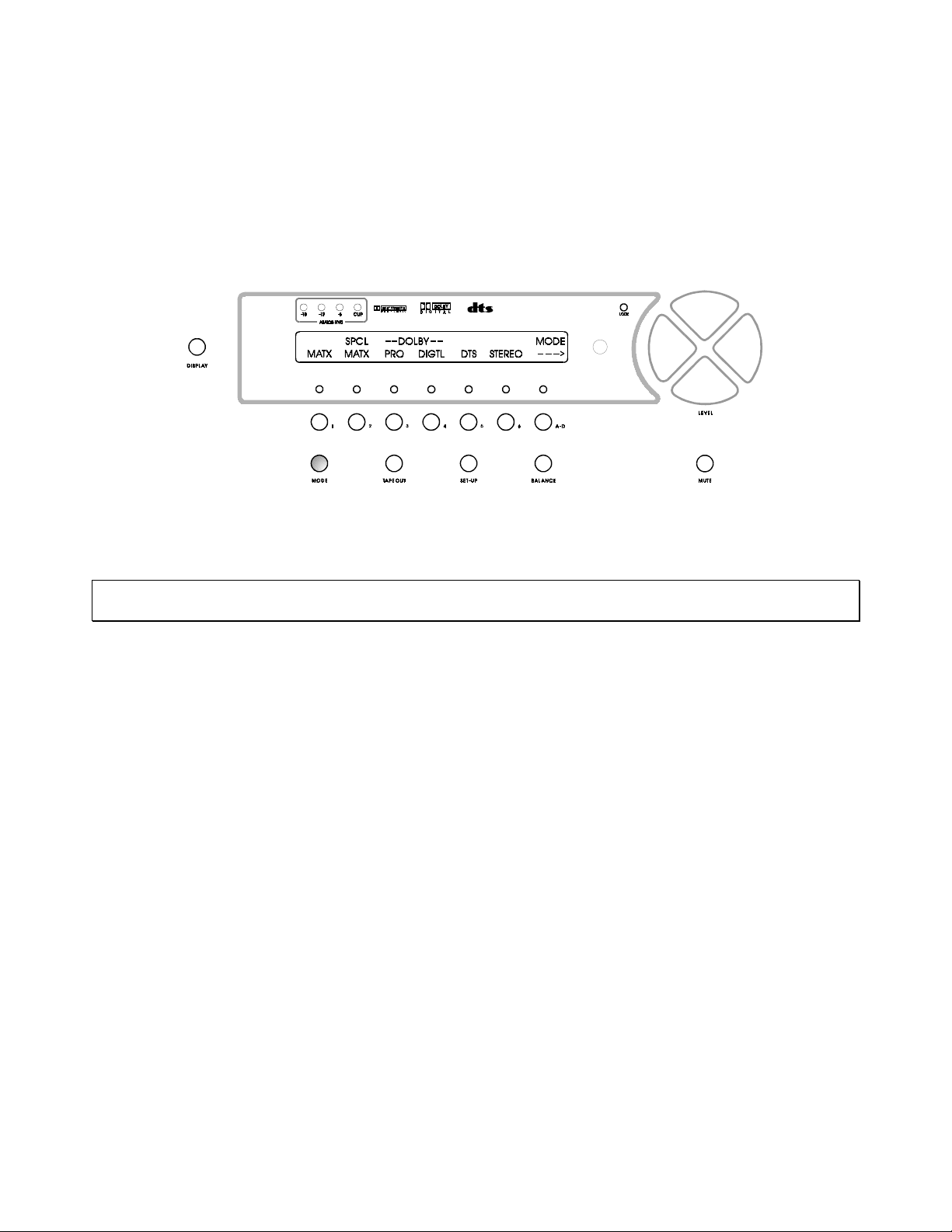
Figure 6 shows the first
MODE
button (shaded in figures 6 and 7) once displays the first page of the
MODE”
A-D
button once will reveal this second page, consisting of additional modes. In the
MODE
MODE”
page and figure 7 shows the second.
is also displayed in the upper right corner with a
A-D
is displayed in the upper right corner and a
button once more will return the user to the first
* * *
MODE
left
menu. This
arrow is
right
arrow displayed
MODE
page.
Figure 6 - Front Panel Display of the MODE Menu - First Page
Press button 1 - 6 to select the desired mode. The corresponding LED above buttons 1 through 6 will
illuminate.
Note
: If a specific feature such as Dolby Digital or DTS is not installed in the Casablanca, its corresponding
selection button (in this case, button 4 or 5) will be disabled.
The first 6 modes shown in figure 6 are described below. The EQ is active in all modes except Analog Direct
and for the front left/right speakers in Analog Matrix.
Simple Matrix (
the signal routed to the surround speakers is equal to left minus right signals. Crossing over any speaker(s)
produces a sub channel.
Special Matrix (
surround speakers.
Dolby Pro Logic (
Dolby Digital (
Please refer to page 22 for additional Dolby Digital options, selectable in the second page of the
menu. If
menu], the Casablanca will automatically search for a valid Dolby Digital signal at both the digital and
input jacks of channels 1 and 2. When detected, the LCD will display
corresponding to the input the signal was detected on. If a Dolby Digital signal is present on both the digital
and RF jacks simultaneously, the Casablanca will lock on to, and display the first one it finds. In this case,
the user can press the
If the Casablanca detects a Dolby Digital signal on a digital input jack of the current channel, the
selection is
message on both the LCD and video monitor:
MATX
): The signal routed to the center speaker is equal to the left plus right input signals and
SPCL MATX
PRO
): When
DIGTL
): (Optional). When this button is selected, Dolby Digital decoding is implemented.
DOLBY DIGITAL
A-D
DIGITAL
, and the
): A mode similar to Dolby Pro Logic with more ambience retrieval in the
PRO
is selected, Dolby Pro Logic decoding is implemented.
SET-UP
is selected, when the
button once to select the other, if desired.
MODE
is
set to
not
**RECEIVING DOLBY DIGITAL SIGNAL**
CHANGING MODE TO DOLBY DIGITAL
MODE
button is pressed once more [to exit the
DOLBY DIGITAL
DIGITAL
, the Casablanca will display the following
or RF above the
A-D
MODE
RF
button,
A-D
and display
15 seconds after the Casablanca ceases to receive this signal, the
DOLBY DIGITAL
as the current mode. However, this is not stored and therefore approximately
11
MODE
will revert back to the previous
 Loading...