

The Speaker Company TTP 248M User Manual

TTP 248M
SERVICE
MANUAL
THERMAL TRANSFER / DIRECT THERMAL BAR CODE PRINTER

TTP-248M Bar Code Printer
Service Manual
TABLE OF CONTENT
1. Foundamentals About the System .............................................................................. 1
Printer Overview ...................................................................................................... 1
Front View ................................................................................................ ........ 1
Rear View ........................................................................................................ 1
1.2 Pinter Specification ............................................................................................ 2
1.3 Available Bar Codes .......................................................................................... 4
1.4 Text Specification .............................................................................................. 5
Specification of Fonts ....................................................................................... 5
File Head of Font ( Fixed 32bytes ) .................................................................. 6
VF1~4 .............................................................................................................. 6
BF3~4 VF3~4 ................................................................................................... 7
2. Supply Specifications ................................................................................................. 8
2.1 Types of Paper .................................................................................................. 8
2.2 Specification ................................................................ ................................ ...... 8
2.3 Ribbon Specification .......................................................................................... 9
3. Circuit Description ................................................................................................. 10
3.1 MCU 10
3.2 MCU PIN Description ...................................................................................... 12
3.3 Reset Circuit .................................................................................................... 21
3.4 Memory System .............................................................................................. 22
3.5 Decoder Circuits .............................................................................................. 23
3.6 Memory Address Map ..................................................................................... 23
3.7 Firmware Address Map ................................................................................... 26
3.8 Power Down Sensor ............................................................................... 27
3.9 Print Head ....................................................................................................... 28
3.10 Motor System Circuit ..................................................................................... 29
3.11 Sensor Circuits .............................................................................................. 30
3.12 Serial Port Circuit .......................................................................................... 33
3.13 Parallel Port Circuit ....................................................................................... 34
3.14 Cutter Drive System ...................................................................................... 35
3.15 PIN Switch Circuits ........................................................................................ 36
3.16 Connector Circuits ......................................................................................... 36
3.17 Optional Items Circuits .................................................................................. 39
4. Machanism ............................................................................................................ 40
4.1 Remove the Covers and LCD Panel ............................................................... 40
i

TTP-248M Bar Code Printer
Service Manual
4.2 Replacing the Mainboard ................................................................................ 43
4.3 Replacing the Power Supply Unit .................................................................... 44
4.4 Replacing the Ribbon Rewind Spindle ............................................................ 45
4.5 Replacing Ribbon Supply Spindle ................................................................... 48
4.6 Replacing Label Supply Spindle ...................................................................... 50
4.7 Replacing Label Rewind Spindle ..................................................................... 52
4.8 Replacing Platen ............................................................................................. 54
4.9 Replacing Motor .............................................................................................. 56
4.10 Replacing Print Head .................................................................................... 58
4.11 Replacing Print Head Pressure Adjustment Knob ......................................... 59
4.12 Replacing Gap/Black Mark Sensor ............................................................... 61
4.14 Replacing Print Head Lift Lever Sensor ........................................................ 64
5. Troubleshooting ........................................................................................................ 65
5.1 Troubleshooting ............................................................................................... 65
5.2 Calibrate Gap/Black Mark Sensor ................................................................... 66
5.3 Self-test ........................................................................................................... 67
5.4 DRAM Clear .................................................................................................... 67
5.5 Diagnosis Operation Procedure ...................................................................... 67
5.6 Cleaning Print Head ........................................................................................ 68
Update History.............................................................................................................. 69
ii
TTP-248M Bar Code Printer
Service Manual
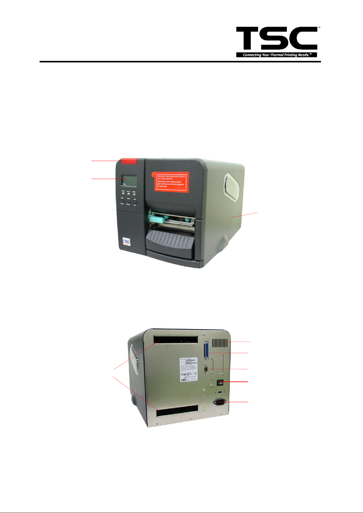
Aux. LED
LCD Display
Printer Cover
External Label
Feed Opening
Aux. Buzzer
Centronics Port
RS-232C Port
Voltage Switch
Power Supply
Connector
1. FOUNDAMENTALS ABOUT THE SYSTEM
Printer Overview
Front View
Rear View
Fig. 1.1 Printer Front View
Fig. 1.2 Printer Rear View
1

TTP-248M Bar Code Printer
Service Manual
Item
Specification
Printing Mode
Thermal transfer and direct thermal
Resolution
203 DPI
Max. Print Length
999 mm
Max. Print Width
104 mm
Print Speed
Selectable speed of 4,6,8 inch per second
Environment
Temperature
5 ~40 OC
Humidity
30 ~ 85 %
Temperature
-10 ~ 60 OC
Humidity
20 ~ 95 %
Ventilation
Free air environment
Sensors
Label gap (256-level), ribbon end (16-level), black
mark (256-level), carriage open, ribbon near end
Memory
Flash Memory 2MB, DRAM 4MB and optional Flash
Memory 8MB
Interface
RS-232C 56000bps ( Max.), Centronics
Cutter
116 mm width (Paper thickness up to 0.28 mm)
Power
100 VAC to 120 VAC, 200 VAC to 240 VAC
Switching mode power supply.
Input Frequency : 50Hz to 60Hz
Input Current : 4.0 Amps at max.
Inrush Current :
40 Amps max. (cold start) at 115 VAC input line
voltage.
80 Amps max. (cold start) at 230 VAC input line
voltage.
Electrical
CPU
HITACH SH 7709A
1.2 Pinter Specification
2

TTP-248M Bar Code Printer
Service Manual
TPH
ROHM KF2004-GL41D 550Ω
Stepping Motor
Mitsumi 24V 7.5 Degrees 4Ω Japan Servo KH56KM
2u023 1.80,24V,0.36Ω
Memory
SDRAM, 1M×16Brt×2 7ns
Flash Memory: (512K×16Bit) ×2 70ns
Compliance
CE, UL/CUL, BSMI, FCC Class A, TÜV-GS
Communication Interface
Communication
RS-232C (DB-9) at 2400, 4800, 9600 or 19200 38400,
56000, 57600, 115200, 128000, 50000 baud rate
Word Length
7 or 8 data bits, 1 or 2 stop bits, selectable parity
Communication Protocol
XON/XOFF and DSR/DTR
Parallel Port
Standard parallel interface
Input Buffer
10KB
3
TTP-248M Bar Code Printer
Service Manual
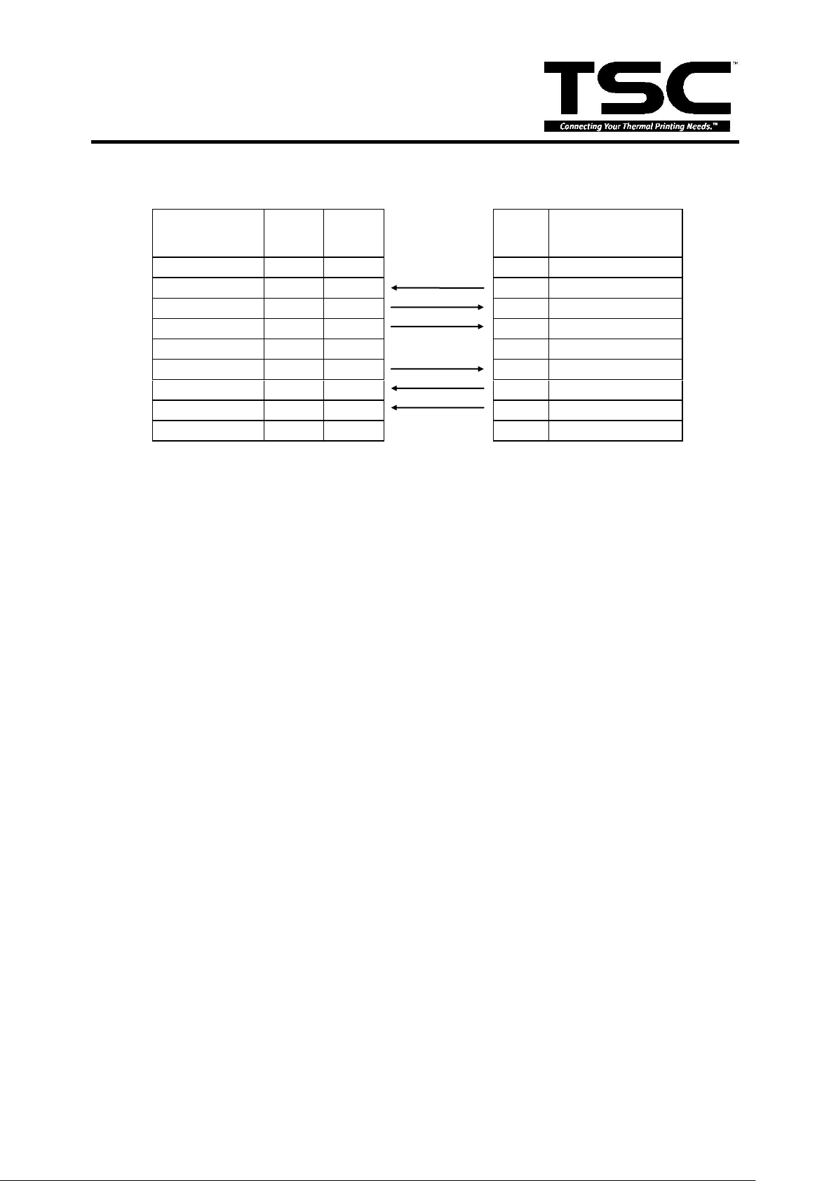
Host
Function
9 Pin
25 Pin
9 Pin
Printer
Function
1
+5V
RxD
2 3 2 TxD
TxD
3 2 3 RxD
DTR
4
20 4
DSR
GND
5 7 5 GND
DSR
6 6 6 RDY
RTS
7 4 7 N/C
CTS
8 5 8 RDY
9
+5V
RS-232 Interface Pin Configuration:
1.3 Available Bar Codes
Code 39
Code 39C
Code 93
Code128UCC
Code128 subsets A.B.C
Code 11
Codabar
Interleave 2 of 5
EAN-8
EAN-13
EAN-128
UPC-A
UPC-E
EAN and UPC 2(5) digits add-on
CPOST
MSI
PLESSEY
POSTNET
4

TTP-248M Bar Code Printer
Service Manual
Font
Width x Length
Font 1
8x12
Font 2
12x20
Font 3
16x24
Font 4
24x32
Font 5
32x48
Font 6
14x19 OCRB
Font 7
21x27 OCRB
Font 8
14x25 OCRA
Font
Width x Length
EAN 1
7x10
EAN 2
14x22
EAN 3
21x33
EAN 4
28x43
EAN 5
35x52
EAN 6
42x64
EAN 7
49x74
EAN 8
56x85
EAN 9
63x97
EAN 10
70x107
Fixed Pixel
Variable Pixel
Singed byte
Double byte
Decode by Table
BF1 X X
EAN-14
ITF14
PDF-417
Maxicode
DataMatrix
1.4 Text Specification
Font 1 to Font 8 are all build-in fonts and BF1 fonts.
EAN 1 to EAN 10 are the fonts used on Barcode UPC and EAN series (they
content numbers only).
The above are the fonts we approve on our printers.
Specification of Fonts
5

TTP-248M Bar Code Printer
Service Manual
BF2 X X
BF3 X X
X
BF4 X X
X
VF1 X X
VF2 X X
VF3 X X
X
VF4 X X
X
Offset 0
B->Bitmap font
Offset 1
0->Fixed pixel 1->Variable Pixel
Offset 2
0->Singed Byte Decode 1->Double Byte
Decode
Offset 3
Decode by table
Offset 4
0-> None 1->Italic
Offset 5-6
Font Height
Offset 7-8
Font Width
Offset 9-10
Font decode start
Offset 11-12
Font decode end
Offset 13
Font decode type
Offset 14
Reserved
Offset 15-16
Font character total
Offset 17-18
Italic Width Variable
Offset 19-31
Reserved
File Head of Font ( Fixed 32bytes )
If ( BF1 BF2 VF1 VF2 )
Offset 32-xx : Font Data
Else if( BF3 BF4 VF3 VF4 )
Offset 32-xx : Decoded Table
Offset xx-xx : Font Data
VF1~4
Font data of variable pixel
(width low byte)(width high byte) Font Data
Font of variable printing spacing is two-bite-width of word in front of the data of
every word.
6

TTP-248M Bar Code Printer
Service Manual
BF3~4 VF3~4
Decode Table
(char low byte) (char high byte) (offset 4 bytes ==> file start to font data)
The font with decade table, the previous two bytes of every word is the code of the
word, and the later four bytes is the displacement from the file head to the position
of the data of the word.
7

TTP-248M Bar Code Printer
Service Manual
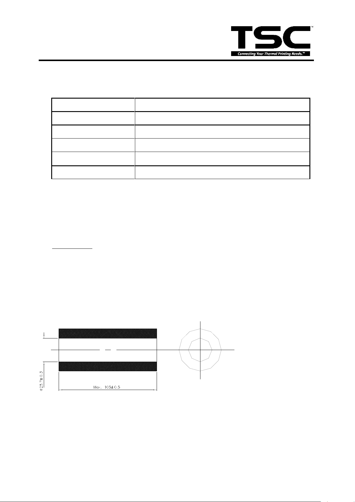
Item
Specification
Type
Label (Continuous, die-cut, fan-fold, ticket, Tag etc.)
Label Width
19~118 mm ( 0.7”~4.65” )
Label Length
10~999 mm ( 0.4”~39.33” )
Label Thickness
0.06~0.25 mm
Label Roll Diameter
203 mm
Paper Core ID
25.7± 0.3 mm
Paper Weight
Less than 280 g/m2
Rewinder Roll diameter
138 mm (Max.) with 1" core
Label Roll Diameter
without Rewinder
254 mm (Max.) with 3" core
Roll Core Diameter
25 ~ 77 mm
Black Mark Height
1.5 mm ( Min.)
Black Mark Width
3 mm ( Min.)
2. SUPPLY SPECIFICATIONS
2.1 Types of Paper
Two types of media are available for TTP-248M/2410M : label and ticket.
In TTP-248M/2410M, there are two types of sensors for paper : gap sensor and
black mark sensor.
Label and ticket can be further classified into direct thermal type or thermal transfer
type.
2.2 Specification
8
TTP-248M Bar Code Printer
Service Manual
Item
Specification
Ribbon Shape
Spool type
Ribbon Width
25.4~114.3 mm
Ribbon Length
450 m
Diameter
Less than 3.5” ( 89 mm)
Roll Up Method
Print surface wound outside as standard.
t4
)d(D
= L
22
2.3 Ribbon Specification
Note: The maximum length of ribbon depends on its thickness and core outside
diameter.
The formula below defines the correlation between ribbon roll length and ribbon core
diameter.
where
,
L = Ribbon length
D = Max. roll diameter
d = Ribbon core outside diameter
t = Ribbon thickness
9
TTP-248M Bar Code Printer
Service Manual
VCC
X1
16MHz
C1
15pF
C2
15pF
GND
C3
470pC4470p
B
y
p
a
s
s
C
a
p
a
c
i
t
o
r
l
i
s
t
GND
VCC
D0
D1
D2
D3
D4
D5
D6
D7
D8
D9
D10
D11
D12
D13
D14
D15
VCC L
L1
0
L2
0
L3
0
EN_MB
INB_R
INA_R
EN_MA
EN_CUTTER
PHASE
/BK
CTSENS
/INB_R
/INA_R
MOTER_C
PEEL_SENS
MOTO R
MOTO R.SCH
EN_MB
INB_R
INA_R
EN_MA
EN_CUTTER
PHASE
/BK
CTSENS
/INB_R
/INA_R
MOTER_C
PEEL_SENS
KEY1
KEY2
KEY3
B1
BUZZER
R10
10K
R11
1K
TH_SENS
HEAD_SENS
CASE_SENS
PEEL_SENS
REND_SENS
D16
D17
D18
D19
D20
D21
D22
D23
D24
D25
D26
D27
D28
D29
D30
D31
VDD
R17
10K
LCD_D0
LCD_D1
LCD_D2
LCD_D3
LCD_D4
LCD_D5
LCD_D6
LCD_D7
LCD_C S2
LCD_C S1
LCD_W /R
GND
GNDD IGITAL GND
SELECT
PE
ERROR
/Wait
/DStrb
/Init
/AStrb
VDD R18
10K
R56
100
C5
220p
VDD
VDD
D0
D1
D2
D3
D4
D5
D6
D7
/Write
Intr
A0
A1
A2
A3
A4
A5
A6
A7
A8
A9
A10
A11
A12
A13
A14
A15
A16
A17
A18
A19
A20
A21
A22
A23
A24
A25
D0
D1
D2
D3
D4
D5
D6
D7
A20
A21
A22
A23
VCC
/Wait
/DStrb
D0
D1
D2
D3
D4
D5
D6
D7
/Write
Intr
/Init
/AStrb
D[0..31] A [0..25]
CKE
CLK
/RAS3L
/CAS
/WE
/WE0/DQM LL
DQM LU
SDRAM
ROM 1
ROM 2
/RESET
/RD
ROM 3
ROM 4
CS0
CS2
CS3
SCK
SDI
SDO
CSI
DQM UL
DQM UU
MEMO RY
MEMO RY.SC H
D[0..31] A [0..25]
CKE
CLK
/RAS3L
/CAS
/WE
/WE0/DQM LL
DQM LU
SDRAM
ROM 1
ROM 2
/RESET
/RD
ROM 3
ROM 4
CS0
CS2
CS3
SCK
SDI
SDO
CSI
DQM UL
DQM UU
/RESET
CLK
CTSENS
LED1
LED2
LED3
/DStrb_I
Intr_I
/Init_I
/AStrb_I
1
2
3
4
5
6
JP1
JTAG
GND
VCC
DI3
DI1
DI2
DI4
CLK
/LAT
TM
STB1
STB2
STB3
STB4
Vdet
/RESET_PH
PRINTHEAD
PRINT.SCH
DI3
DI1
DI2
DI4
CLK
/LAT
TM
STB1
STB2
STB3
STB4
Vdet
/RESET_PH
PH_I
/RESE T
CLK
STB1_I
STB2_I
STB3_I
STB4_I
VCC
GND
C1+
1
V+
2
C1-
3
C2+
4
C2-
5
V-
6
T2OUT
7
R2IN
8
R2OUT
9
T2IN
10
T1IN
11
R1OUT
12
R1IN
13
T1OUT
14
VCC
16
GND
15
U31
SP3232E
C9
0.1u
C10
0.1u
VCC
C11
0.1u
C17
0.1u
GND
GND
L7
BEAD 300
L8
BEAD 300
L9
BEAD 300
L10
BEAD 300
C12
0.1uGND
F1
1A
TX
RX
DSR
RDY
GND
TM
Vdet
TM Vdet
GND
1
2
3
4
JP2
RNE_END
RTC_O
RTC _O
X2
32.768kHz
C18
22pF
C19
22pF
GND
GND
VCC
VCC
5
9
4
8
3
7
2
6
1
JP3
DB9_1
/LAT_P
CTSENS
R57
100
R58
100
R59
820
/RESE T
D[0..31]
VCC
GAP_SENSER
1
2
3
4
5
6
7
8
9
10
11
12
13
14
15
16
17
18
19
20
21
22
23
24
25
26
27
28
29
30
31
32
33
34
35
36
37
38
JP4
CENTRON IC
TTP-2410_MAIN
VDD
AVSS
CS0
CS2
CS3
CS0
CS2
CS3
SCK
SDI
SDO
SCK
SDI
SDO
VCC
1
RxD
2
TxD
3
GND4D+
5
D-
6
R-
7
R+
8
U32
LTC490
GND
VCC
R80
120
R81
120
L12
INDUC TOR1
L13
INDUC TOR1
L14
INDUC TOR1
L15
INDUC TOR1
VCC CSI
CSI
R19
10K
P_INT
POWER powe r.sch
P_INT
1 2
U3A
74HC1 4
3 4
U3B
74HC1 4
5 6
U3C
74HC1 4
R20
10K
R21
10K
R22
10K
VCC
AVCC
AVSS
AVSS
GND
L4
0
DIGITAL GND
C20
0.01uF
BC1
10uF
R60
100
R61
100
D2
1N4148
D3
1N4148D41N4148D51N4148
C23
0.1uF
C24
0.1uF
AVCC VCC
L5
0
AVCC AVC C
AVSS AVSS
R12
1K
R13
1K
R62
100
D6
1N4148D71N4148
C25
0.1uF
AVCC
AVSS
R14
1K
3
2
1
4
11
U5A
LM324
R63
100
GND
VDD
GND8 9
U3D
74HC1 4
10 11
U3E
74HC1 4
BM_ SEN
1
2
JP5
2PIN
MA
MB
R23
1.5K
R24
1.5K
VDD
GND
VCC
R64
100
R25
10K
12 13
U3F
74HC1 4
5
6
7
U5B
LM324
R65
100
GAP_E
BM_ E
R26
10K
R27
4.7K
ME
BC2
0.1uF
BC3
0.1uF
BC4
0.1uF
BC5
0.1uF
BC6
0.1uF
BC7
0.1uF
BC8
0.1uF
BC9
0.1uF
BC1 0
0.1uF
BC1 1
0.1uF
BC1 2
0.1uF
BC1 3
0.1uF
BC1 4
0.1uF
BC1 5
0.1uF
BC1 6
0.1uF
BC1 7
0.1uF
BC1 8
0.1uF
BC1 9
0.1uF
BC2 0
0.1uF
BC2 1
0.1uF
BC2 2
0.1uF
BC2 3
0.1uF
BC2 4
0.1uF
BC2 5
0.1uF
BC2 6
0.1uF
BC2 7
0.1uF
BC2 8
0.1uF
C26
0.1uF
VCC
BC2 9
0.1uF
BC3 0
0.1uF
BC3 1
0.1uF
BC3 2
0.1uF
VCC
VCC
VCC
GND
R28
10K
1 2
U6A 74HCT14
Q3
2SC2411K
R29
10K
VDD
1
2
JP9
NMIGND
R30
10K
VCC
SW1
SW-PB
A0
A1
A2
A3
A4
A5
A6
A7
A8
A9
A10
A11
A12
A13
A14
A15
A16
A17
A18
A19
A20
A21
A22
A23
A24
A25
VCC
VDD
VDD
P21
P22
VCC 1VCC 2
VCC 3
R66
100
R67
100
34
U6B 74HC T14
56
U6C
74HCT14
8 9
U6D
74HCT14
PE
SELECT
ERROR
ERROR
SELECT
PE
VCC IO
1
GTS3
2
GTS4
3
4
GTS1
5
GTS2
6
7
VCC INT
8
9
10
11
12
13
14
15
16
17
GND
18
19
2021222324
25
26
27
28
GND
29
GCK1
30
31
GCK2
32
33
34
35
GND
36
VCC IO
37
GCK3
38
39
40
41
VCC INT
42
43
44
45
46
GND
47
48
49
50
51
52
53
54
VCC IO
55
56
57
58
59
60
61
GND
62
TDI
63
64
TMS
65
66
TCK
67
68
69
70
71
GND
72
VCC IO
73
74
7576
77
78
79
80
81
82
83
VCC INT
84
85
86
87
88
GND89GND
90
91
92
93
94
95
96
97
98
GND
99
100
101
102
103
104
105
106
107
GND
108
VCC IO
109
110
111
112
113
GND
114
115
116
117
118
119
120
121
TDO
122
GND
123
124
125
126
VCC IO
127
128
129
130
131
132
133
134
135
136
137
138
139
140
VCC INT
141
142
GSR
143
GND
144
U2
XC951 44XL
R31
10K
R32
10K
10 11
U6E 74HC T14
R33
10K
R34
10K
R82
4.7K
C391uVDD
GND
LCD_D/I
LCD_E
R35
10K
R36
10K
VDD
1 2
3 4
5 6
7 8
9 10
11 12
13 14
15 16
17 18
19 20
21 22
23 24
25 26
27 28
29 30
JP10
PANL
R37
1K
VDD
R68
100
GND
LCD_B L
KEY1
KEY2 KEY3
LED1 LED2
LED3
YELLOW
RED
Q1
HSC94 5
12 13
U6F
74HCT14
PH_I
/LAT_P
1
2
JP11
BUZZER
RB
RA
Q4
HSC94 5
R38
10K
R69
100
Q5
HSC94 5
R39
10K
R70
100
VDD
R_END1
R_END2
R_END3
R_END0
MOTER_E
MOTER_C
RED
YELLOW
HEAD_SENS
CASE_SENS
REND_SENS
R_END
SENSOR
SENSOR.SC H
HEAD_SENS
CASE_SENS
REND_SENS
R_END
HEAD_SENS
CASE_SENS
1 2
U9A
74LS05
3 4
U9B
74LS05
5 6
U9C
74LS05
89
U9D
74LS05
R84
3.3K
R85
1.8K
R86
910
R87
430
R_END
R_END
REND_SENS
PEEL_SENS
A0
53
A1
54
A2
55
A3
56
A4
58
A5
60
A6
61
A7
62
A8
63
A9
64
A10
65
A11
66
A12
67
A13
68
A14
70
A15
72
A16
73
A17
74
A18
75
A19
76
A20
77
A21
78
A22
80
A23
82
A24
84
A25
86
VccQ59VccQ71VccQ85VccQ97VccQ 111
VccQ 163
VccQ 183
VssQ57VssQ69VssQ83VssQ95VssQ109
VssQ161
VssQ181
Vss79Vss27
Vss
132
Vss
152
Vss
153
Vss
173
VssQ19VssQ33VssQ
45
VccQ47VccQ35VccQ
21
Vcc
175
Vcc
154
Vcc
134
Vcc81Vcc 29
D0
52
D1
51
D2
50
D3
49
D4
48
D5
46
D6
44
D7
43
D8
42
D9
41
D10
40
D11
39
D12
38
D13
37
D14
36
D15
34
PTB7/D31
13
PTB6/D30
14
PTB5/D29
15
PTB4/D28
16
PTB3/D27
17
PTB2/D26
18
PTB1/D25
20
PTB0/D24
22
PTA7/D23
23
PTA6/D22
24
PTA5/D21
25
PTA4/D20
26
PTA3/D19
28
PTA2/D18
30
PTA1/D17
31
PTA0/D16
32
/MC S7/PINT7/PTC7
177
/MC S6/PINT6/PTC6
178
/MC S5/PINT5/PTC5
179
/MC S4/PINT4/PTC4
180
/MC S3/PINT3/PTC3
185
/MC S2/PINT2/PTC2
186
/MC S1/PINT1/PTC1
187
/MC S0/PINT0/PTC0
188
TxD0/SCPT0
164
SCK0/SC PT1
165
TxD1/SCPT2
166
SCK1/SC PT3
167
TxD2/SCPT4
168
SCK2/SC PT5
169
RTS2/SCPT6
170
RxD0/SC PT0
171
RxD1/SC PT2
172
RxD2/SC PT4
174
CTS2/IRQ5/S CPT7
176
XTA L
155
EXT AL
156
XTA L2
4
EXT AL2
5
Vss- RTC
6
Vcc-RT C
3
AVcc205
AVs s208
Vss- PLL1
147
Vss- PLL2
148
Vcc-PL L1
145
Vcc-PL L2
150
AN0/PTL0
199
AN1/PTL1
200
AN2/PTL2
201
AN3/PTL3
202
AN4/PTL4
203
AN5/PTL5
204
DA1/A N6/PTL6
206
DA0/A N7/PTL7
207
MD1
1
MD2
2
MD3
195
MD4
196
MD5
197
AVs s198
MD0
144
CAP1
146
CAP2
149
CKIO
162
CA
194
/RAS3L/PTJ0
106
/RAS2L/PTJ1
107
/CASLL/CAS /PTJ2
108
/CASU /CASLH/PTJ3
110
/CASH L/PTJ4
112
/CASH H/PTJ5
113
STATUS0/PTJ6
157
STATUS1/PTJ7
158
TDO/PTE0
120
/CAS2L/PTE6
116
/CAS2H /PTE3
117
/RAS3U /PTE2
118
/CAS2U /PTE1
119
/CE2A/PTE4
103
/CE2B/PTE5
104
PTE7
94
/RESE TM
124
/RESE TP
193
PTG0/AUTAD A0
135
PTG1/AUTAD A1
133
PTG2/AUTAD A2
131
PTG3/AUTAD A3
130
PTG4
129
/ASEBRK AK/PTG5
128
/ASMD O/PTG6
127
IOIS16/PTG7
126
/WAIT
123
/BACK
121
/BRE Q
122
/IRQOU T
160
DRAK 1/PTD0
190
DRAK 0/PTD1
189
RESTOUT/PTD2
184
WAKEUP /PTD3
182
/DREQ0/PTD 4
191
/DREQ1/PTD 6
192
/DACK 0/PTD5
114
/DACK 1/PTD7
115
/RD
88
/WE0/DQM LL
89
/WE1/DQM LU//WE
90
/WE2/DQM UL//ICIOR D/PTK6
91
/WE3/DQM UU//IC IOWR/PTK7
92
/WR/R D
93
/CS0/M CS0
96
/CS2/PTK0
98
/CS3/PTK1
99
/CS4/PTK2
100
/CS5//CE1A /PTK3
101
/BS/PTK4
87
CKE/PTK5
105
NMI
7
/CS6//CE1B
102
PTF7/PINT15
136
TRST/PTF6/PINT14
137
TRST/PTF5/PINT13
138
TRST/PTF4/PINT12
139
PTF3/PINT11
140
/IRLS2/PTF2/PINT10
141
/IRLS1/PTF1/PINT9
142
/IRLS0/PTF0/PINT8
143
/IRLO/IRQ0/PTH 0
8
/IRL1/IRQ1/PTH1
9
/IRL2/IRQ2/PTH2
10
/IRL3/IRQ3/PTH3
11
IRQ4/PTH4
12
ADTRG /PTH5
125
PTH6
151
TCL K/PT H7
159
SH7709A
U1
SH-7709A
RB
RA
BUZZER
R40
10K
VCC
R71
100
BUZZER_O
BUZZER_O
BUZZER
DQM UL
DQM UL
DQM UU
DQM UU
BK
BK
VMM
R41
10K
VCC
VDD
AGND
AGND
LCD_D0
LCD_D1 LCD_D 2
LCD_D3 LCD_D 4
LCD_D5 LCD_D 6
LCD_D7 LCD_C S1
LCD_C S2 LC D_/RES
LCD_R /W LCD _D/I
LCD_E BAC KLIGHT
R Y
10
9
8
U5C
LM324
R126
100
MOTER_C
B_IN1
B_IN2
B_IN3
B_OUT1
B_OUT2
B_OUT1
B_OUT2
B_IN1
B_IN2
B_IN3
AD1
AD2
BK_IO
BK_IO .SCH
B_OUT1
B_OUT2
B_IN1
B_IN2
B_IN3
AD1
AD2
B_OUT1
B_OUT2
B_IN1
B_IN2
B_IN3
CKE
/WE
/RD
DQM LL
DQM LU
/CAS
/RAS3L
A24
A25
/RST
1
GND
2
VCC 3
3
VCC 5
4
VCC A
5
U10
LTC1728
VCC
VDD
VCC L
R2
3.4K
R3
3.0K
GND
PR12
10K
PC4
220p
PC1
220p
PC2
220p
PC3
220p
PR1 10 K
PR2
10K
PR3
10K
PR4
10K
PR5
10K
PR6
10K
PR7
10K
PR8
10K
PR9
10K PR10 10 K
PR11
10K
PR14
10K
PR15
10K
PR16
10K
PR17
10K
PR18
10K
PR19
10K
PR20
10K
PR21
10K
PR22
100
PR23
100
PR24
100
PR25
100
ROM 1
R130
10K
C77
0.1uF
C78
0.1uF
GND GND
VCC
VMM
U
9
-
>
AD1
AD2
AD1
AD2
10 11
U4E
74HC1 4
1213
U4F
74HC1 4
1011
U9E
74LS05
1213
U9F
74LS05
VCC
GND
1
2
JP27
2PIN
R95
10K
L24
BEAD 080 5 NB 220
1
2
JP28
2PIN
PE_I
SELECT_I
ERROR _I
PE_I
SELECT_I
ERROR _I
VDD
GND
GND
Q14
HSC94 5
Q15
HSC94 5
1
2
3
4
5
6
7
JP12
GAP_E&B M_SEN
R137
100
TXD
TXD
L31
0
L30
0
R138
100
R139
100
R140
100
C82
0.1u
C83
0.1u
C84
0.1u
GND
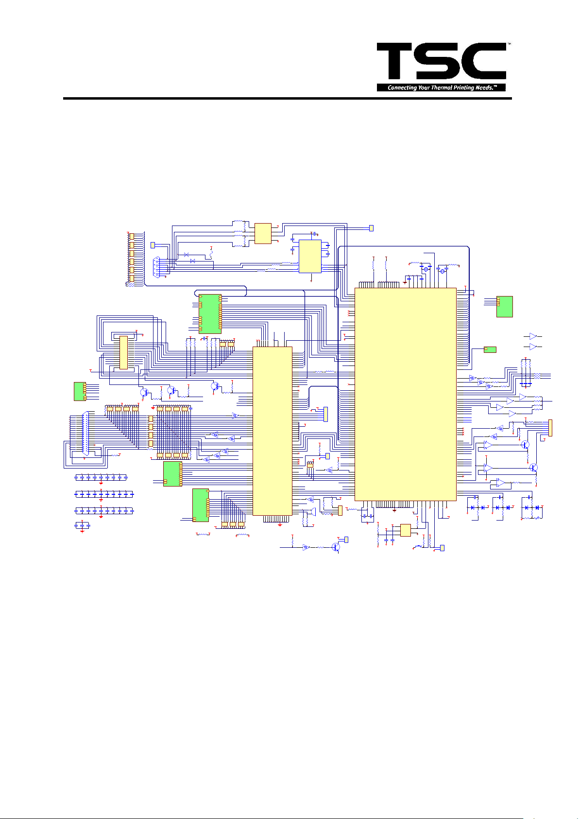
3. CIRCUIT DESCRIPTION
3.1 MCU
The mainboard of TTP-248M/2410M includes seven system blocks:
A. Memory System (decoder & memory block)
B. Motor System (stepping motor, DC motor and cutter block)
C. Print Head System
D. Communication System (serial & parallel port block)
E. Power System
F. Sensor System
G. LCD Display System
Fig. 3.1 MCU Circuit Diagram
10
TTP-248M Bar Code Printer
Service Manual
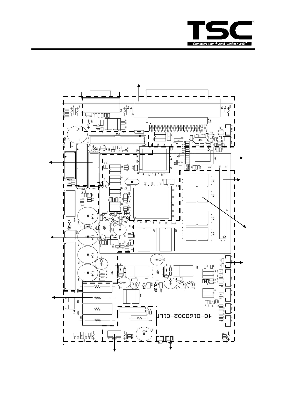
Fig. 3.2 System Block of PCB
MCU
Communication port
Decoder
System
External Memory
Connector
Memory
System
Cutter System
Motor
System
Power
System
Print
Head
Connector
Sensor
Connector
Option I/O
The figure below shows the PCB system area:
11
TTP-248M Bar Code Printer
Service Manual
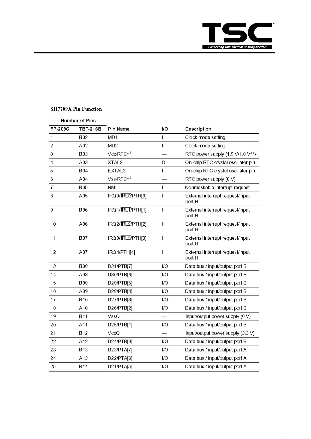
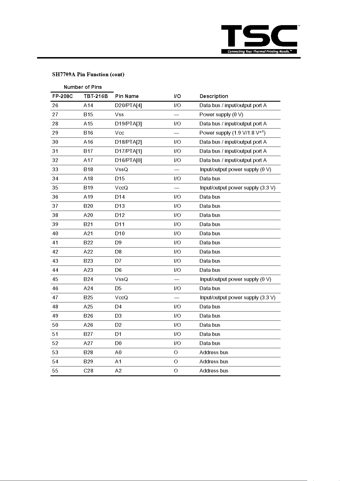
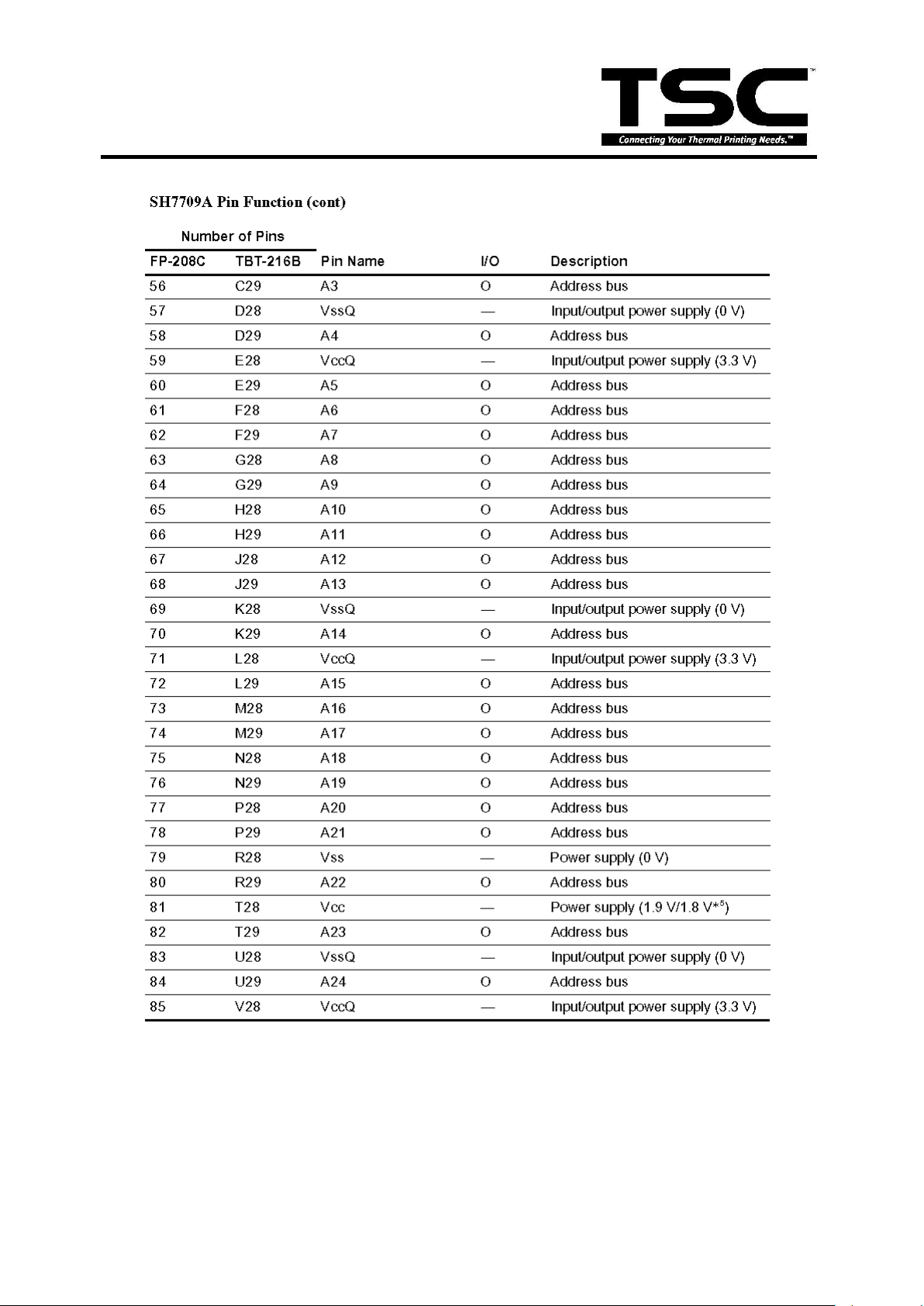
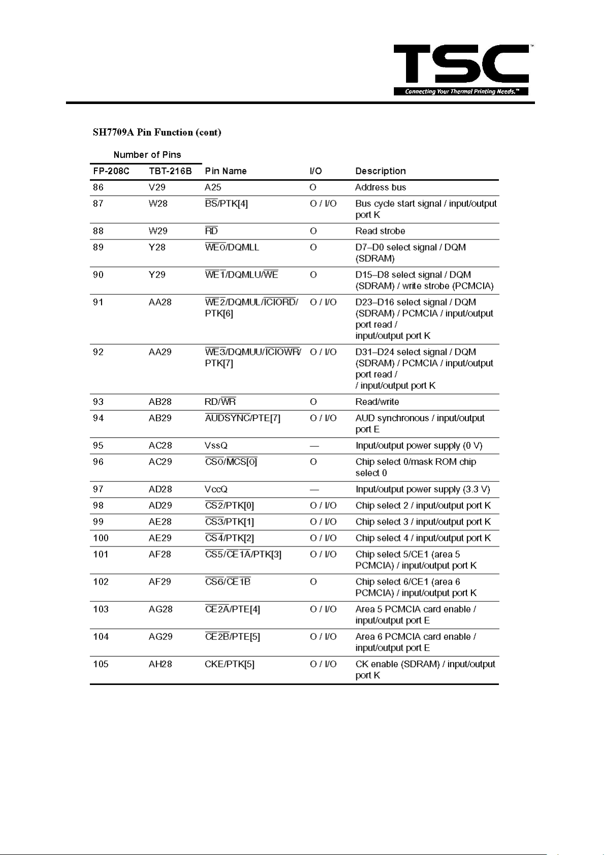
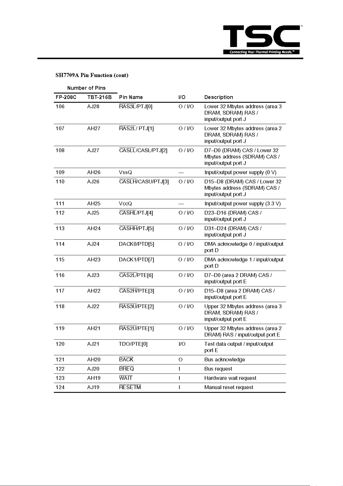
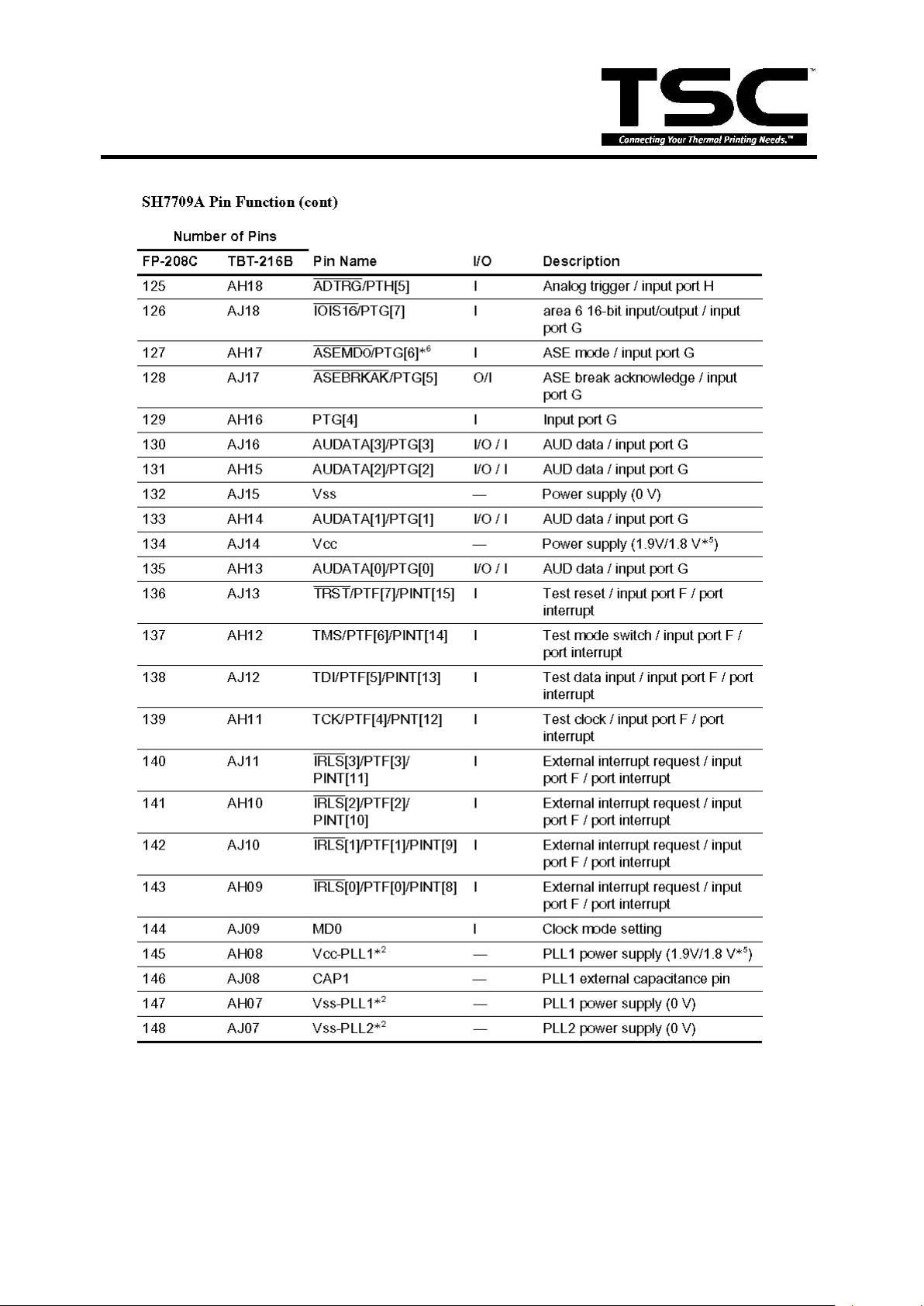
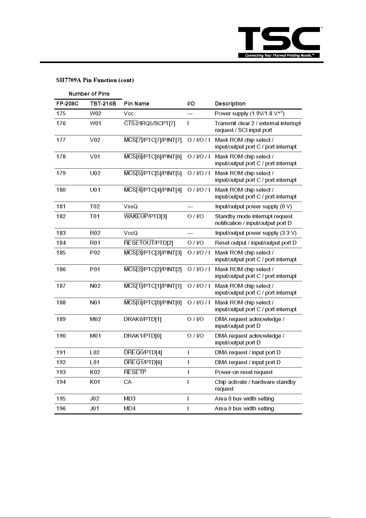
3.2 MCU PIN Description
12
TTP-248M Bar Code Printer
Service Manual
13
TTP-248M Bar Code Printer
Service Manual
14
TTP-248M Bar Code Printer
Service Manual
15
TTP-248M Bar Code Printer
Service Manual
16
TTP-248M Bar Code Printer
Service Manual
17

TTP-248M Bar Code Printer
Service Manual
18
TTP-248M Bar Code Printer
Service Manual
19
 Loading...