

The Speaker Company TTP-343C, TTP-244CE, TTP-245C User Manual
USER’S
MANUAL
TTP-245C / TTP-343C / TTP-244CE
THERMAL TRANSFER / DIRECT THERMAL
BAR CODE PRINTER

i
Contents
Copyright Declaration .................................................................................... i
1. Introduction ................................................................................................ ii
1.1 Product Introduction ............................................................................... ii
1.2 Compliances ............................................................................................ ii
2. Operations Overview ................................................................................. 1
2.1 Unpacking and Inspection ...................................................................... 1
2.2 Printer Overview ...................................................................................... 2
2.2.1 Front View ...................................................................................... 2
2.2.2 Interior view .................................................................................... 4
2.2.3 Rear View ........................................................................................ 5
3. Setup ........................................................................................................... 6
3.1 Setting Up the Printer .............................................................................. 6
3.2 Open / Close the Top Cover .................................................................... 7
3.3 Loading the Ribbon ................................................................................. 8
3.4 Loading the Media ................................................................................. 11
3.4.1 Loading the media ....................................................................... 11
3.4.2 External Label Roll Mount Installation (Option) ........................ 13
3.4.3 Loading Media in Peel-off Mode (Option) .................................. 15
3.4.4 Loading Media in Cutter Mode (Option) ..................................... 17
3.5 Diagnostic Tool ...................................................................................... 18
3.5.1 Start the Diagnostic Tool ............................................................. 18
3.5.2 Printer Function (Calibrate sensor, Ethernet setup, RTC
setup………) .......................................................................................... 19
3.6 Setting Ethernet by Diagnostic Utility .................................................. 20
3.6.1 Using USB interface to setup Ethernet interface ...................... 20
3.6.2 Using RS-232 interface to setup Ethernet interface ................. 21
3.6.3 Using Ethernet interface to setup Ethernet interface ............... 22
3.7 Install SD Memory Card ......................................................................... 24
4. LED and Button Functions ...................................................................... 26
4.1 LED indicator ......................................................................................... 26
4.2 Regular button function ........................................................................ 26
4.3 Power on utilities ................................................................................... 26
4.3.1 Ribbon and Gap/Black Mark Sensor Calibration ...................... 27
4.3.2 Gap/Black Mark Calibration, Self-test and Dump Mode ........... 28
4.3.3 Printer Initialization...................................................................... 31

ii
4.3.4 Set Black Mark Sensor as Media Sensor and Calibrate the Black
Mark Sensor .......................................................................................... 32
4.3.5 Set Gap Sensor as Media Sensor and Calibrate the Gap Sensor
32
4.3.6 Skip AUTO.BAS ............................................................................ 33
5. Troubleshooting ....................................................................................... 34
5.1 LED Status .............................................................................................. 34
5.2 Print Quality ........................................................................................... 35
6. Maintenance ............................................................................................. 36
Revise History .............................................................................................. 38

i
Copyright Declaration
Information in this subject to change without notice and does not represent a commitment on
the part of TSC Auto ID Technology Co., Ltd.. No part of this manual may be reproduced or
transmitted in any form by any means, for any purpose other than the purchaser’s personal
use, without the expressed written permission of TSC Auto ID Technology Co., Ltd..

ii
CAUTION
1. HAZARDOUS MOVING PARTS IN CUTTER MODULE. KEEP FINGER AND OTHER BODY
PARTS AWAY.
2. THE MAIN BOARD INCLUDES REAL TIME CLOCK FEATURE HAS LITHIUM BATTERY
CR2032 INSTALLED. RISK OF EXPLOSION IF BATTERY IS REPLACED BY AN
INCORRECT TYPE.
3. DISPOSE OF USED BATTERIES ACCORDING TO THE MANUFACTURER INSTRUCTIONS.
1. Introduction
1.1 Product Introduction
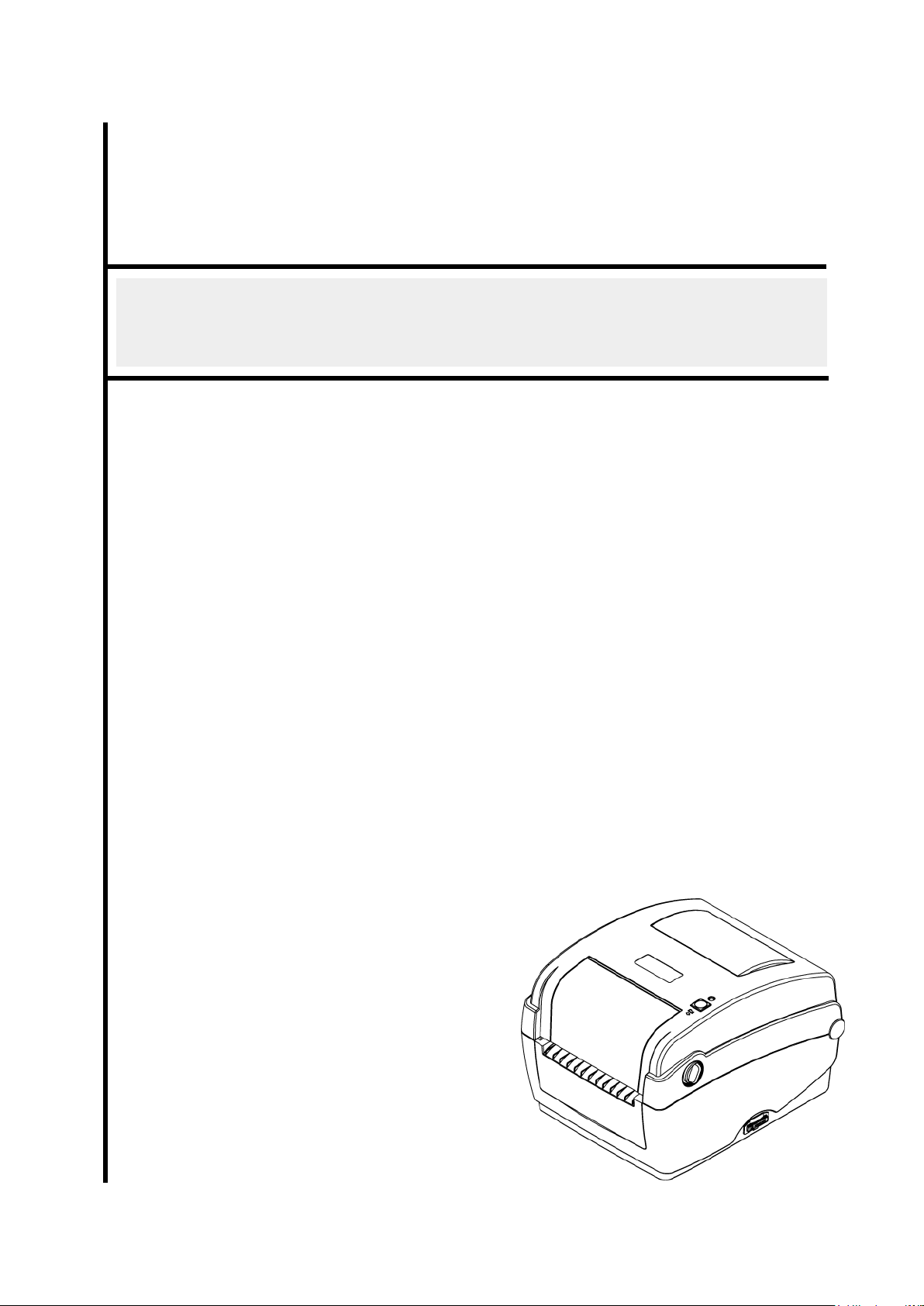
Thank you for purchasing TSC bar code printer. Although the printer takes only a small
amount of space, it delivers reliable, superior performance.
This printer provides both thermal transfer and direct thermal printing at user selectable speed
of: 2.0, 3.0, 4.0 or 5.0 ips, for TTP-245C series; 2.0 or 3.0 ips for TTP-343C series. It accepts
roll feed, die-cut, and fan-fold labels for both thermal transfer and direct thermal printing. All
common bar codes formats are available. Fonts and bar codes can be printed in 4 directions,
8 different alphanumeric bitmap fonts and a build-in true type font capability. You will enjoy
high throughput for printing labels with this printer.
1.2 Compliances
CE Class B:
EN55022: 1998+A1: 2000+A2: 2003
EN55024: 1998+A1: 2001+A2: 2003 IEC 61000-4 Series
EN61000-3-2: 2006 & EN61000-3-3: 1995+A1: 2001
FCC Part 15, Class B
UL, CUL
C-Tick:
CFR 47, Part 15/CISPR 22 3rd Edition: 1997, Class B
ANSI C63.4: 2003
Canadian ICES-003
TÜ V/Safety: EN60950: 2000
Wichtige Sicherheits-Hinweise
1. Bitte lesen Sie diese Hinweis sorgfältig durch.
2. Heben Sie diese Anleitung fűr den späteren Gebrauch auf.
3. Vor jedem Reinigen ist das Gerät vom Stromentz zu trennen. Verwenden Sie keine
Flüssig-oder Aerosolreiniger. Am besten eignet sich ein angefeuchtetes Tuch zur
Reinigung.
4. Die Netzanschluß-Steckdose soll nahe dem Gerät angebracht und leicht zugänglich
sein.
5. Das Gerät ist vor Feuchtigkeit zu schűtzen.
6. Bei der Aufstellung des Gerätes ist auf sicheren Stand zu achten. Ein Kippen oder
Fallen könnte Beschädigungen hervorrufen.
7. Beachten Sie beim Anschluß ans Stromnetz die Anschlußwerte.
8. Dieses Gerät kann bis zu einer Außentemperatur von maximal 40℃ betrieben werden.

iii
WARNUNG!
GEFÄ HRLICHE BEWEGLICHE TEILE – FINGER UND ANDERE KÖ RPERTEILE
FERNHALTEN!
VORSICHT!
EXPLOSIONSGEFAHR BEI ERSATZ DER
BATTERIE DURCH UNZULÄ SSIGEN TYP.
VERBRAUCHTE BATTERIEN IMMER
VORSCHRIFTSGEMÄ SS ENTSORGEN!
B 급기기
(가정용 정보통신기기)
이 기기는 가정용으로 전자파 적합등록을 한 기기로서
주거지역에서는 물론 모든 지역에서 사용할 수 있습니다.
Note:
* Continuous printing will cause printer motor overheat. Printer will stop printing automatically
about 10~15 minutes until motor is cooling down. Please don’t turn off power when printer pauses
or the data transferred to printer buffer will be lost.
* The maximum printing ratio per dot line is 15% for this printer. To print the full web black line, the
maximum black line height is limited to 40 dots, which is 5mm for 203 DPI resolution printer and
3.3mm for 300 DPI resolution printers.
* The max. full web black bar is limited to 5 mm only, otherwise this may damage the power supply.
2. Operations Overview
2.1 Unpacking and Inspection
This printer has been specially packaged to withstand damage during shipping.
Please carefully inspect the packaging and printer upon receiving the bar code printer.
Please retain the packaging materials in case you need to reship the printer.
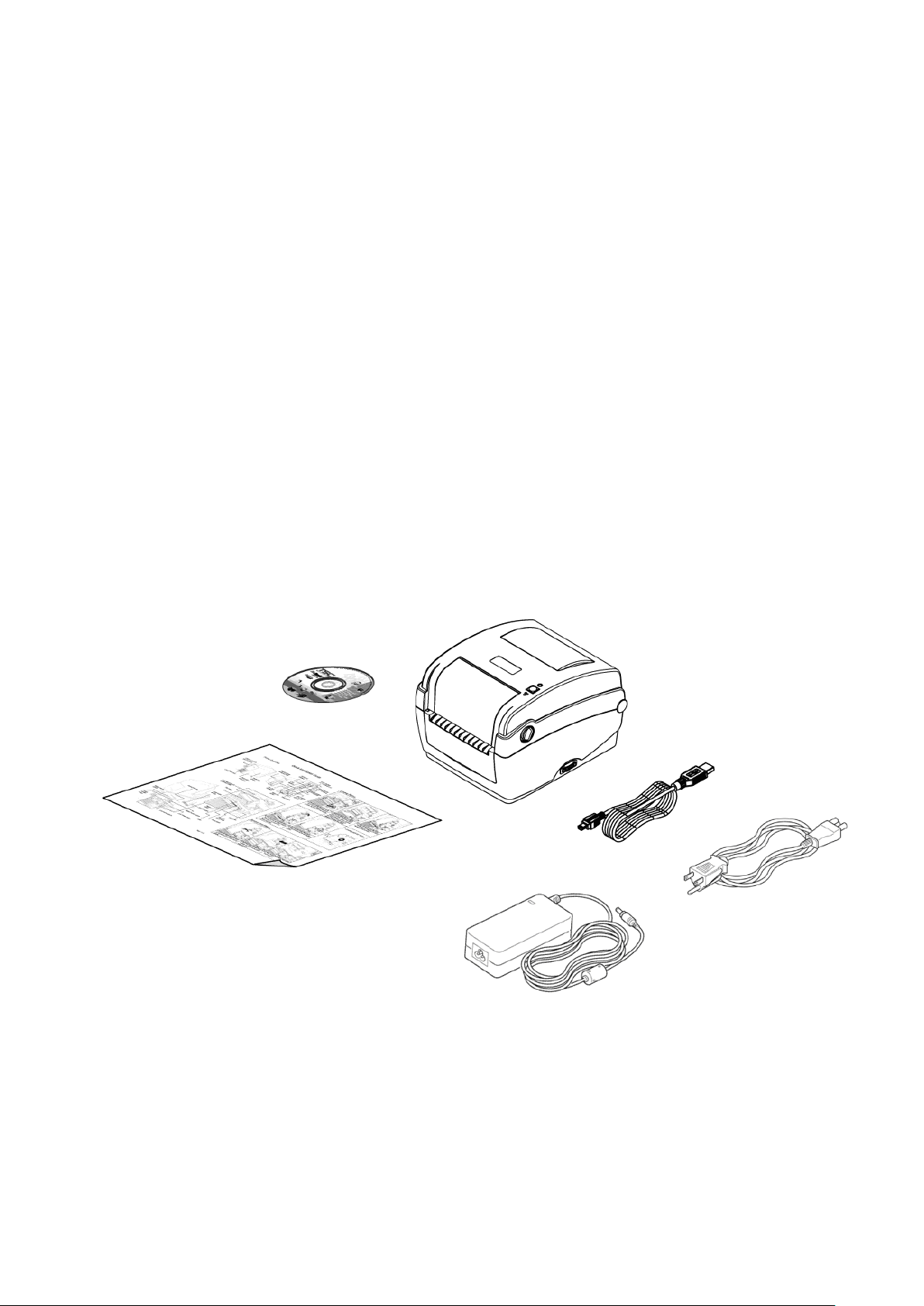
Unpacking the printer, the following items are included in the carton.
One printer unit
One Windows labeling software/Windows driver CD disk
One quick installation guide
One power cord
One auto switching power supply
One USB interface cable
If any parts are missing, please contact the Customer Service Department of your
purchased reseller or distributor.
2
SD card spec
SD card capacity
Approved SD card manufacturer
V1.0, V1.1
128 MB
SanDisk, Transcend
V1.0, V1.1
256 MB
SanDisk, Transcend, Panasonic
V1.0, V1.1
512 MB
SanDisk, Transcend, Panasonic
V1.0, V1.1
1 GB
SanDisk, Transcend, Panasonic
V2.0 SDHC CLASS 4
4 GB
V2.0 SDHC CLASS 6
4 GB
SanDisk, Transcend, Panasonic
V1.0, V1.1
microSD 128 MB
Transcend, Panasonic
V1.0, V1.1
microSD 256 MB
Transcend, Panasonic
1
2
6 3 4
5
2.2 Printer Overview
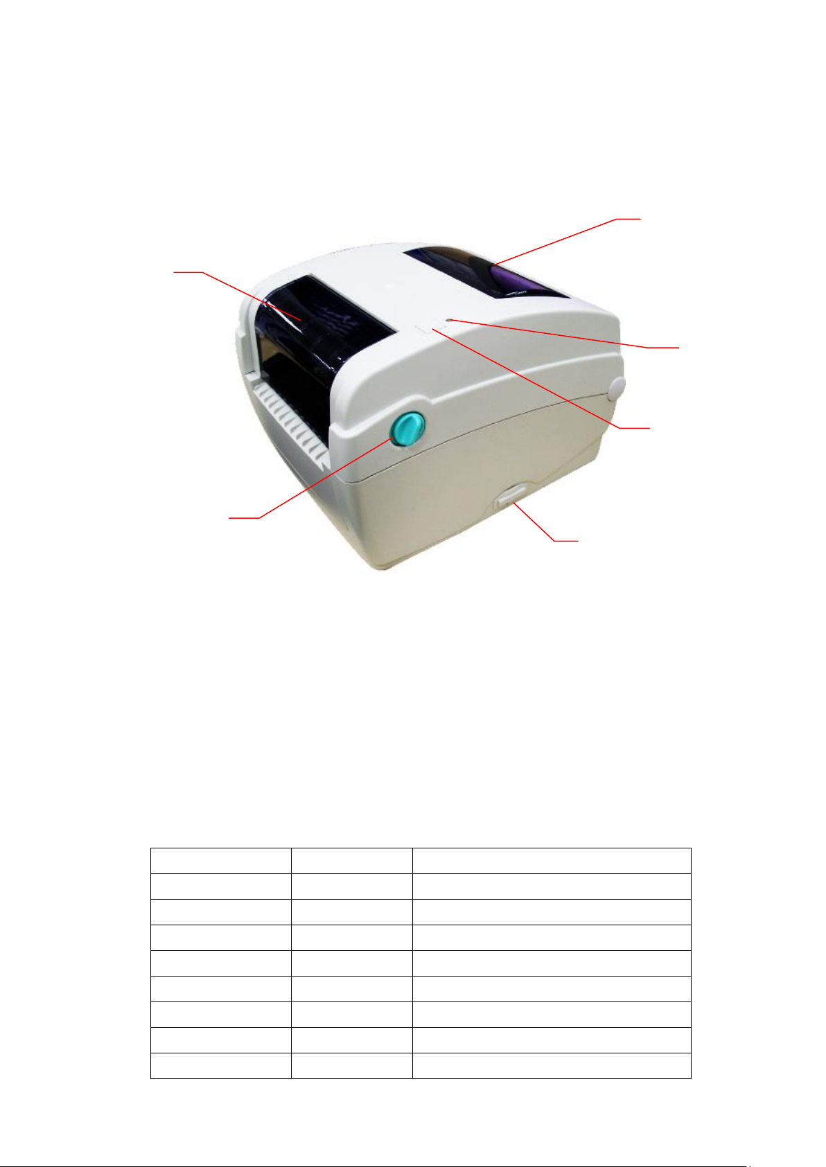
2.2.1 Front View
1. Ribbon access cover
2. Top cover open lever
3. Media view window
4. LED indicator
5. Feed button
6. SD card socket
* Recommended SD card specification.

3
V1.0, V1.1
microSD 512 MB
Panasonic
V1.0, V1.1
microSD 1 GB
Transcend, Panasonic
V2.0 SDHC CLASS 4
microSD 4 GB
Panasonic
V2.0 SDHC CLASS 6
microSD 4 GB
Transcend
V1.0, V1.1
miniSD 128 MB
Transcend, Panasonic
V1.0, V1.1
miniSD 256 MB
Transcend, Panasonic
V1.0, V1.1
miniSD 512 MB
Transcend, Panasonic
V1.0, V1.1
miniSD 1 GB
Transcend, Panasonic
V2.0 SDHC CLASS 4
miniSD 4 GB
Transcend
V2.0 SDHC CLASS 6
miniSD 4 GB
- The DOS FAT file system is supported for the SD card.
- Folders/files stored in the SD card should be in the 8.3 filename format
- The miniSD/microSD card to SD card slot adapter is required.
4
9
11
10
5 4 3
8
7
1
2
12
6
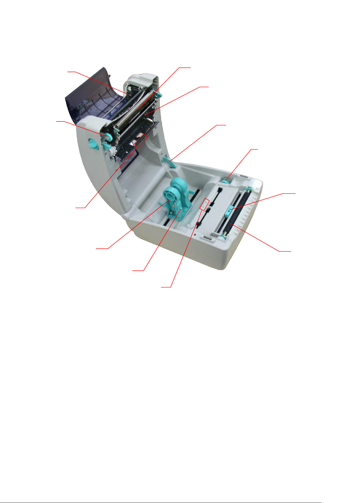
2.2.2 Interior view
1. Ribbon rewind hub
2. Ribbon rewind gear
3. Gap sensor (receiver)
4. Media holder
5. Media holder lock switch
6. Gap sensor (transmitter)
7. Printhead
8. Ribbon supply hub
9. Top cover support
10. Media guide adjustment knob
11. Black mark sensor
12. Platen roller
5
1
3
5 4 2 6 7
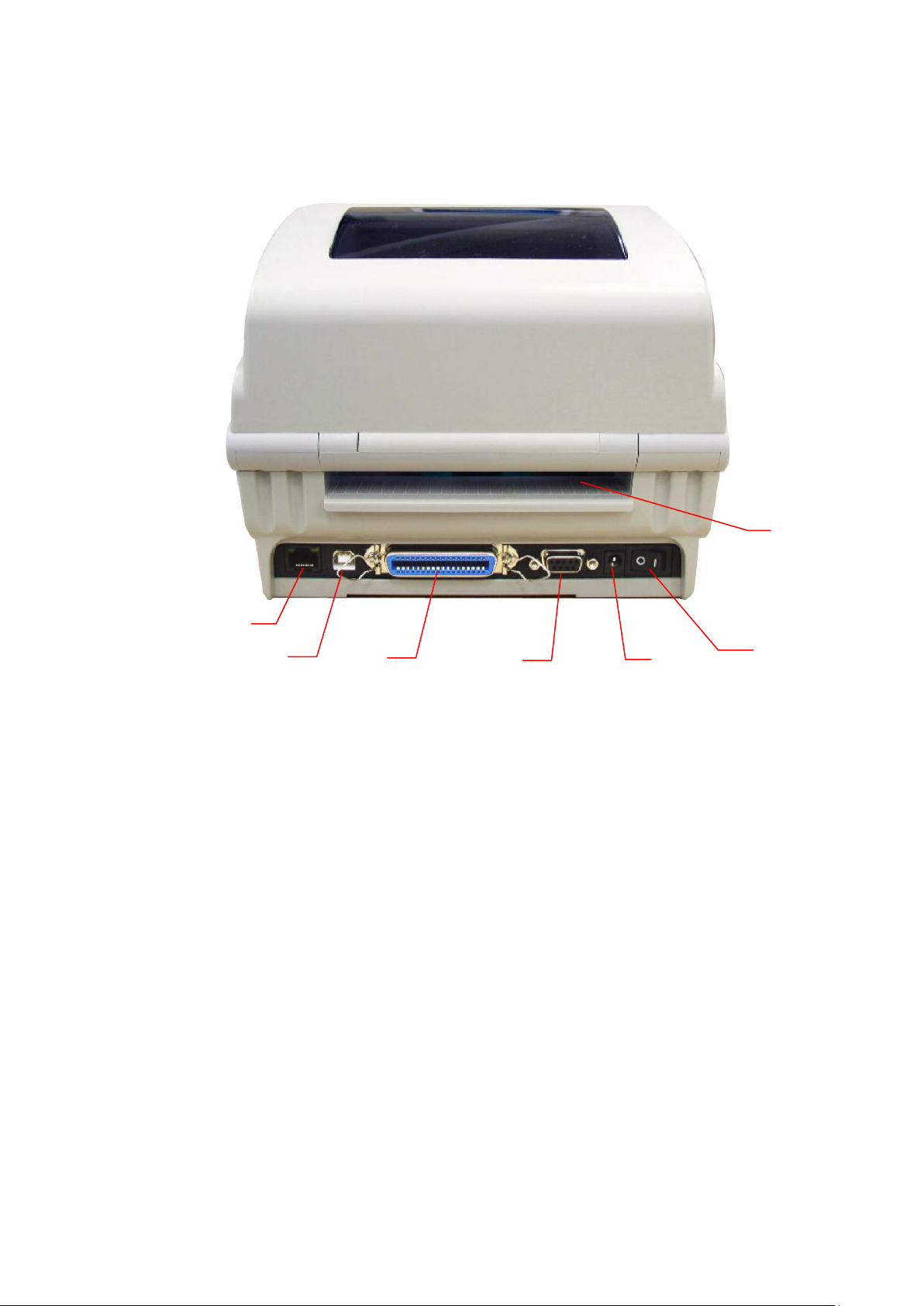
2.2.3 Rear View
1. Ethernet interface
2. USB interface
3. Centronics interface
4. RS-232C interface
5. Power jack socket
6. Power switch
7. Fan-fold paper entrance chute
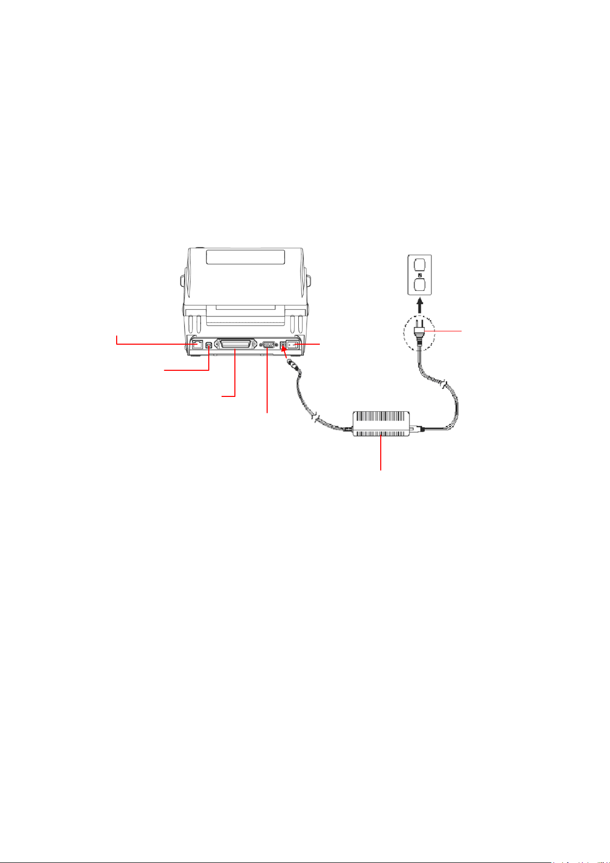
6
Power Supply
Plug
Power
Switch
USB interface
RS-232C interface
Centronics interface
Ethernet RJ-45
interface
3. Setup
3.1 Setting up the Printer
1. Place the printer on a flat, secure surface.
2. Make sure the power switch is off.
3. Connect the printer to the computer with the provided USB cable.
4. Plug the power cord into the AC power cord socket at the rear of the printer, and
then plug the power cord into a properly grounded power outlet.
Note:
Please switch OFF printer power switch prior to plug in the power cord to printer power jack.
7
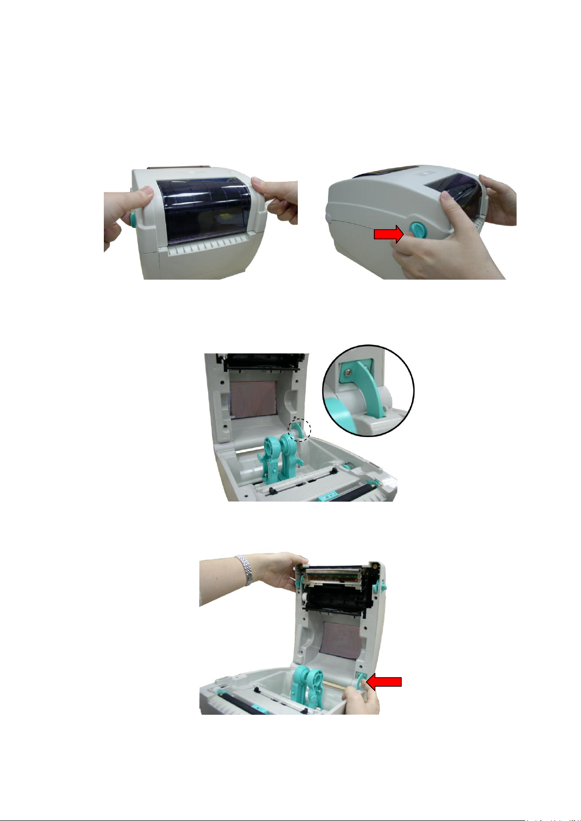
3.2 Open / Close the Top Cover
1. Open the printer top cover by pulling the tabs located on each side towards the front
of the printer, then lift the top cover to the maximum open angle.
2. A top cover support at the rear of the printer will engage with lower inner cover to
hold the printer top cover open.
3. Hold the top cover and press the top cover support to disengage the top cover
support with lower inner cover. Gently close the top cover.
8
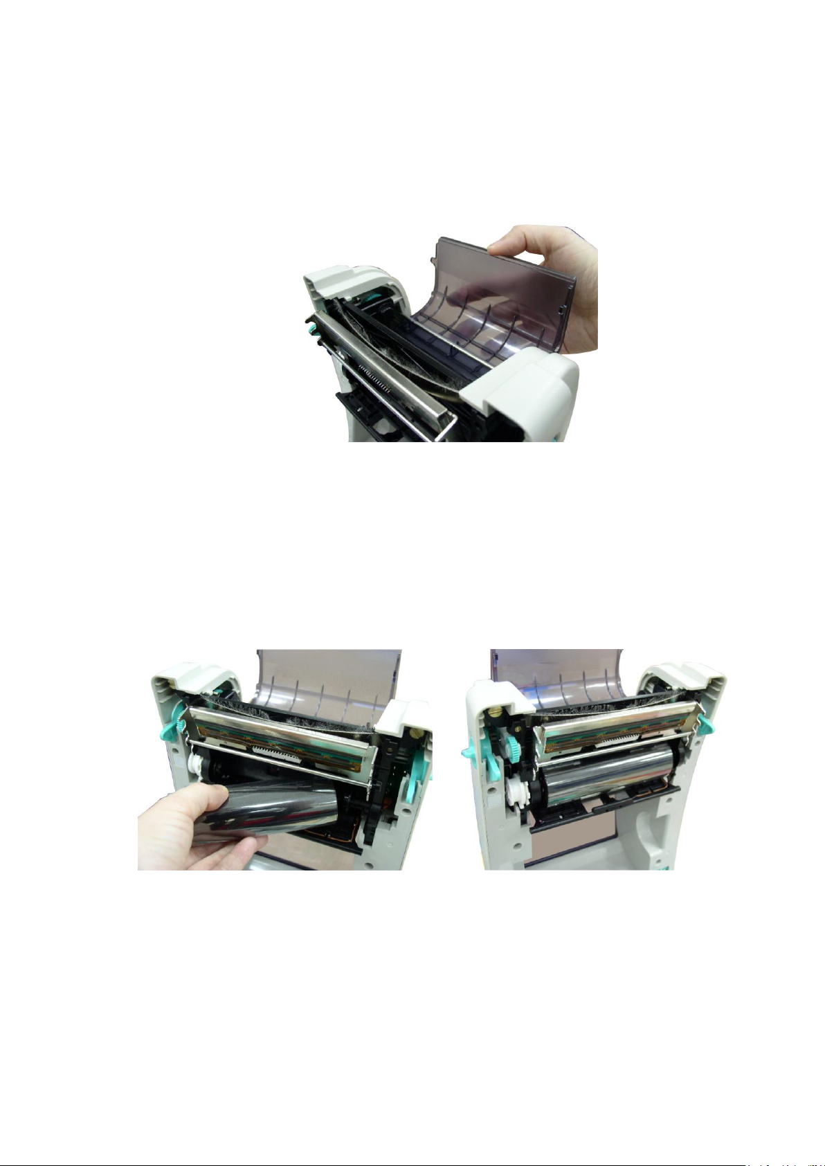
3.3 Loading the Ribbon
1. Open the printer’s top cover by pulling the top cover open levers located on each
side of the printer and lifting the top cover to the maximum open angle.
2. Open the ribbon access cover.
Note:
1. In normal printing mode, ribbon access cover can be opened while opens the top cover.
Ribbon access cover can be closed while top cover is open or close.
2. In peeler and cutter mode, please open the top cover then the ribbon access cover can be
opened or closed.
3. Insert the ribbon right side onto the supply hub. Align the notches on the left side
and mount onto the spokes.
4. Insert the paper core right side onto the rewind hub. Align the notches on the left
side and mount onto the spokes.
 Loading...