

Page 1
Page 2
WARNINGS
WARNING: TO REDUCE THE RISK OF
FIRE OR SHOCK HAZARD, DO NOT EXPOSE
THIS PRODUCT TO RAIN OR MOISTURE.
CAUTION
RISK OF ELECTRIC SHOCK
DO NOT OPEN
CAUTION: TO PREVENT THE RISK OF
ELECTRIC SHOCK, DO NOT REMOVE COVER
OR BACK. NO USER-SERVICEABLE PARTS
INSIDE. REFER SERVICING TO QUALIFIED
PERSONNEL.
This symbol is intended to alert you
of the presence of un-insulated
dangerous voltage within the
product's enclosure that might be of
sufficient magnitude to constitute a
risk of electric shock. Do not open
the product's case.
This symbol is intended to inform
you that important operating and
maintenance instructions are
included in the literature
accompanying this product.
This CD player is made and tested to meet
exacting safety standards. It meets FCC
requirements and complies with safety
performance standards of the U.S.
Department of Health and Human Services.
Warnings:
! This CD player employs a laser light beam.
Only a qualified service person should
remove the cover or attempt to service this
device, due to possible eye injury.
! The use of controls, adjustments, or
procedures other than those specified
herein might result in hazardous radiation
exposure.
! The apparatus shall be used in an open
area.
CAUTION
This compact disc player is classified as a
CLASS 1 LASER product.
The CLASS 1 LASER PRODUCT label is
located on the rear panel.
CAUTION
TO PREVENT ELECTRIC SHOCK, MATCH
WIDE BLADE OF PLUG TO WIDE SLOT,
FULLY INSERT.
DRIPPING WARNING
The product shall not be exposed to dripping
or splashing and that no objects filled with
liquids, such as vases, shall be placed on the
product.
VENTILATION W ARNING
The normal ventilation of the product shall not
be impeded for intended use.
CAUTION!
Invisible laser radiation when open and inter
locks defeated. Avoid exposure to beam.
IMPORTANT
Since CD circuitry may cause interference to
other radio tuners nearby, switch this unit off
when not in use or move it away from the
affected radio tuner.
1
Page 3

WARNINGS
NOTE: This digital apparatus does not exceed the Class B limits for radio noise emissions from digital apparatus as
set out in the Radio Interference Regulations of Industry Canada. These limits are designed to provide reasonable
protection against harmful Nterference in a residential installation. This equipment generates, uses and can radiate
radio frequency energy and, if not installed and used in accordance with the instructions, may cause harmful
interference to radio communications. However, there is no guarantee that interference will not occur in a particular
installation. If this equipment does cause harmful interference to radio or television (which can be determined by
turning the equipment off), the user is encouraged to try to correct the interference by one or more of the following
measures:
! Reorient or relocate the receiving antenna.
! Increase the separation between the equipment and receiver.
! Connect the equipment into an outlet on a circuit different from that to which the receiver is connected.
! Consult the dealer or an experienced radio / TV technician for help.
IMPORTANT SAFETY INSTRUCTIONS
1. Read Instructions - All the safety and operating instructions should be read before the product is operated.
2. Retain Instructions - The safety and operating instructions should be retained for future reference.
3. Heed Warnings - All warnings on the product and in the operating instructions should be adhered to.
4. Follow Instructions - All operating and use instructions should be followed.
5. Cleaning - Unplug this product from the wall outlet before cleaning. Do not use liquid cleaners or aerosol
cleaners. Use a damp cloth for cleaning the exterior only. Do NOT attempt to clean the inside.
6. Attachments - Do not use attachments not recommended by the product manufacturer as they may cause
hazards.
7. Water and Moisture - Do not use this product near water - for example, near a bath tub, wash bowl, kitchen
sink, or laundry tub; in a wet basement, or near a swimming pool, and the like.
8. Accessories - Do not place this product on an unstable cart, stand, tripod, bracket, or table. The product may
fall, causing serious injury to a child or adult, and serious damage to the product. Use only with a cart, stand,
tripod, bracket, or table recommended by the manufacturer, or sold with the product. Any mounting of the
product should follow the manufacturer's instructions, and should use a mounting accessory recommended by
the manufacturer.
9. A product and cart combination should be moved with care. Quick stops, excessive
force, and uneven surfaces may cause the appliance and cart Combination to overturn.
10. Ventilation - Slots and openings in the cabinet are provided for ventilation and to ensure reliable operation of
the product and to protect it from overheating, and these openings must not be blocked or covered. The
openings should never be blocked by placing the product on a bed, sofa, rug, or other similar surface. This
product should not be placed in a built-in installation such as a bookcase or rack unless proper ventilation is
provided.
11. Power Sources - This product should be operated only from the type of power source indicated on the marking
label. If you are not sure of the type of power supply to your home, consult your product dealer or local power
company. For products intended to operate from battery power, or other sources, refer to the operating
instruction.
12. Grounding or Polarization - This product may be equipped with a polarized alternating current line plug (a
plug having one blade wider than the other). This plug will fit into the power outlet only one way. This is a safety
feature. If you are unable to insert the plug fully into the outlet, try reversing the plug. If the plug should still fail to
fit, contact your electrician to replace your obsolete outlet. Do not defeat the safety purpose of the polarized
plug.
Alternate Warnings - This product may be equipped with a three-wire grounding-type plug, a plug having a
third (grounding) pin. This plug will only fit into a grounding-type power outlet. This is a safety feature. If you are
unable to insert the plug into the outlet, contact your electrician to replace your obsolete outlet. Do not defeat
the safety purpose of the grounding-type plug.
2
Page 4
IMPORTANT SAFETY INSTRUCTIONS
13. Power-Cord Protection - Power supply cords should be routed so that they are not likely to be walked on or
pinched by items placed upon or against them, paying particular attention to cords at plugs, convenience
receptacles, and the point where they exit from the product.
14. Protective Attachment Plug - The product is equipped with an attachment plug having overload protection.
This is a safety feature. See Instruction Manual for replacement or resetting of protective device. If
replacement of the plug is required, be sure the service technician has used a replacement plug specified by
the manufacturer that has the same overload protection as the original plug.
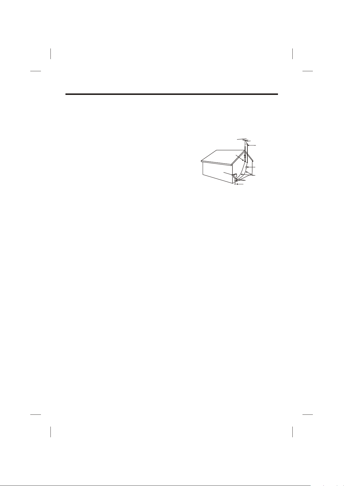
15. Outdoor Antenna Grounding - If an outside antenna is connected
to the receiver, be sure the antenna system is grounded so as to
provide some protection against voltage surges and built-up static
charges. Article 810 of the National Electrical Code, ANSI/NFP A 70,
GROUND
CLAMP
provides information with regard to proper grounding of the mast
and supporting structure, grounding of the lead-in wire to an
antenna-discharge unit, size of grounding conductors, location of
antenna-discharge unit, connection to grounding electrodes, and
ELECTRIC
SERVICE
EQUIPMENT
requirements for the grounding Electrode. See figure:
NEC-NATIONAL ELECTRICAL CODE
S2898A
16. Lightning - For added protection for this product during a lightning storm, or when it is left unattended and
unused for long periods of time, unplug it from the wall outlet and disconnect the antenna or cable system. This
will prevent damage to the product due to lightning and power-line surges.
17. Power Lines - An outside antenna system should not be located in the vicinity of overhead power lines or other
electric light or power circuits, or where it can fall into such power lines or circuits. When installing an outside
antenna system, extreme care should be taken to keep from touching such power lines or circuits as contact
with them might be fatal.
18. Overloading - Do not overload wall outlets, extension cords, or integral convenience receptacles as this can
result in a risk of fire or electric shock.
19. Object and Liquid Entry - Never push objects of any kind into this product through openings as they may
touch dangerous voltage points or short-out parts that could result in a fire or electric shock. Never spill liquid of
any kind on the product.
20. Servicing - Do not attempt to service this product yourself as opening or removing covers may expose you to
dangerous voltage or other hazards. Refer all servicing to qualified service personnel.
21. Damage Requiring Service - Unplug this product from the wall outlet and refer servicing to qualified service
personnel under the following conditions:
a) When the power-supply cord or plug is damaged,
b) If liquid has been spilled, or objects have fallen into the product,
c) If the product has been exposed to rain or water,
d) If the product does not operate normally by following the operating instructions. Adjust only those
controls that are covered by the operating instructions as an improper adjustment of other controls may
result in damage and will often require extensive work by a qualified technician to restore the product to
its normal operation.
e) If the product has been dropped or damaged in any way, and
f) When the product exhibits a distinct change in performance - this indicates a need for service.
22. Replacement Parts - When replacement parts are required, be sure the service technician has used
replacement parts specified by the manufacturer or have the same characteristics as the original part.
Unauthorized substitutions may result in fire, electric shock, or other hazards.
23. Safety Check - Upon completion of any service or repairs to this product, ask the service technician to perform
safety checks to determine that the product is in proper operating condition.
24. Wall or Ceiling Mounting - The product should be mounted to a wall or ceiling only as recommended by the
manufacturer.
25. Heat - The product should be situated away from heat sources such as radiators, heat registers, stoves, or
other products (including amplifiers) that produce heat.
ANTENNA
LEAD IN
WIRE
ANTENNA
DISCHARGE UNIT
(NEC SECTION 810-20)
GROUNDING CONDUCTORS
(NEC SECTION 810-21)
GROUND CLAMPS
POWER SERVICE GROUNDING
ELECTRODE SYSTEM
(NEC ART 250. PART H)
3
Page 5

INTRODUCTION
Your Pedestal CDG Karaoke System will provide you with fun and entert ainment. It can let you
be the “star” as you sing along with your favorite recordings and hear your voice with the music
through the system’s speaker.
This karaoke center is compact and designed to include many features, yet it is easy to use.
After just a few simple instructions, you will become an expert. Before you attempt use your unit,
please read this manual thoroughly to familiarize yourself with all the features available and the
sections of the manual that describe their operation. Next, go to the section for the specific
operation you wish to perform.
For your easy reference, listed here are some of the main features of this karaoke center:
Lyrics on TV screen - displays the lyrics with the tempo of music when playing CD+G discs.
Auto Voice Control (A.V.C.) - lets you replace the original singer's voice with your own voice
when any prerecorded, multiplex disc is played. To activate, just rotate mic volume to a
comfortable listening level, and Auto Voice Control for the best balance between playback and
microphone levels.
Balance Control - lets you adjust the balance between the prerecorded original singer's voice
and the music if you use a multiplex karaoke disc.
Echo Control - lets you add an echo to enrich your voice for a concert hall effect.
Master Volume Control - lets you turn the volume control clockwise or counter - clockwise until
desired volume level is obtained.
-
Built - In Speaker - lets you share the music with your family or friends.
Auxiliary Output Jacks - lets you connect another audio output component, such as an
equalizer/booster or a PA system.
Headphone Jack - lets you connect the headphones instead of using the built-in speaker.
lift up camera lens to display your image on the Singing Machine’s monitor or TV.
4
Page 6
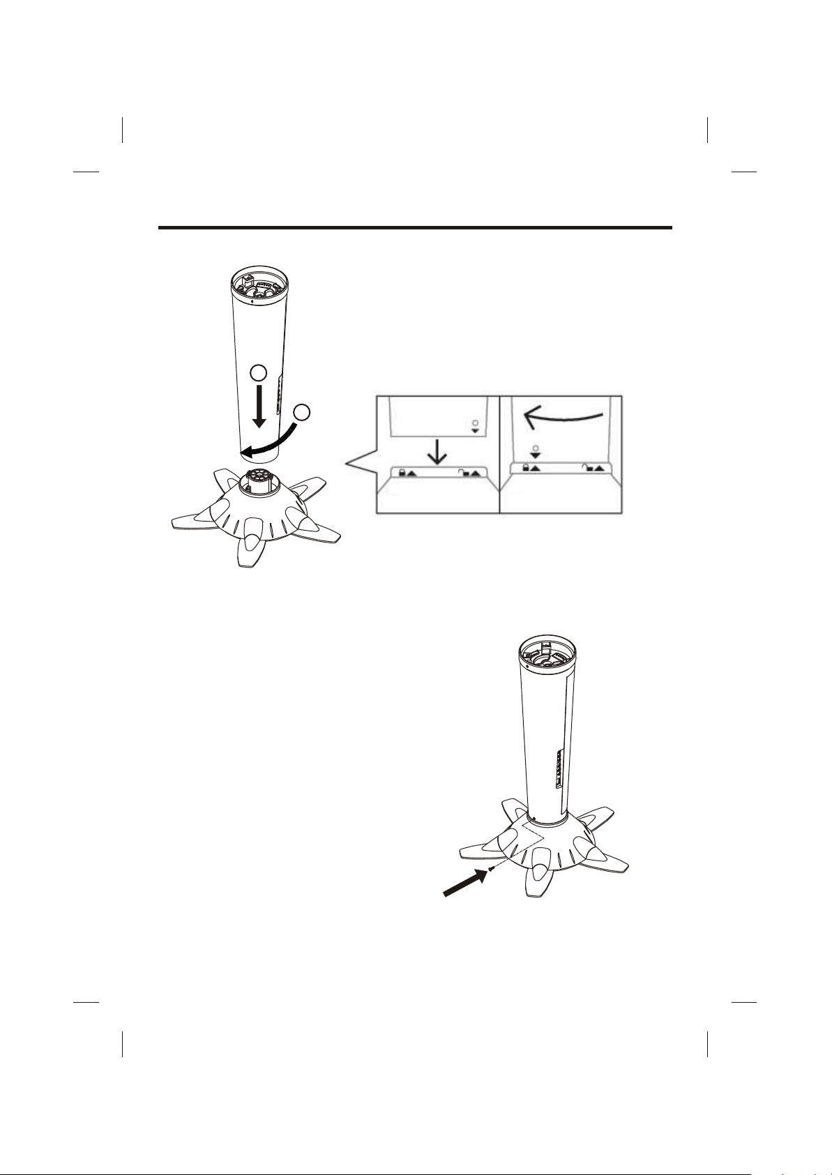
INSTALLATION
1
STEP 1
1. Join the speaker (middle) into the stand
(bottom) according to the installation
illustration.
2
STEP 2
2. Tighten a self tapping screw at the bottom of
the speaker (middle).
5
Page 7
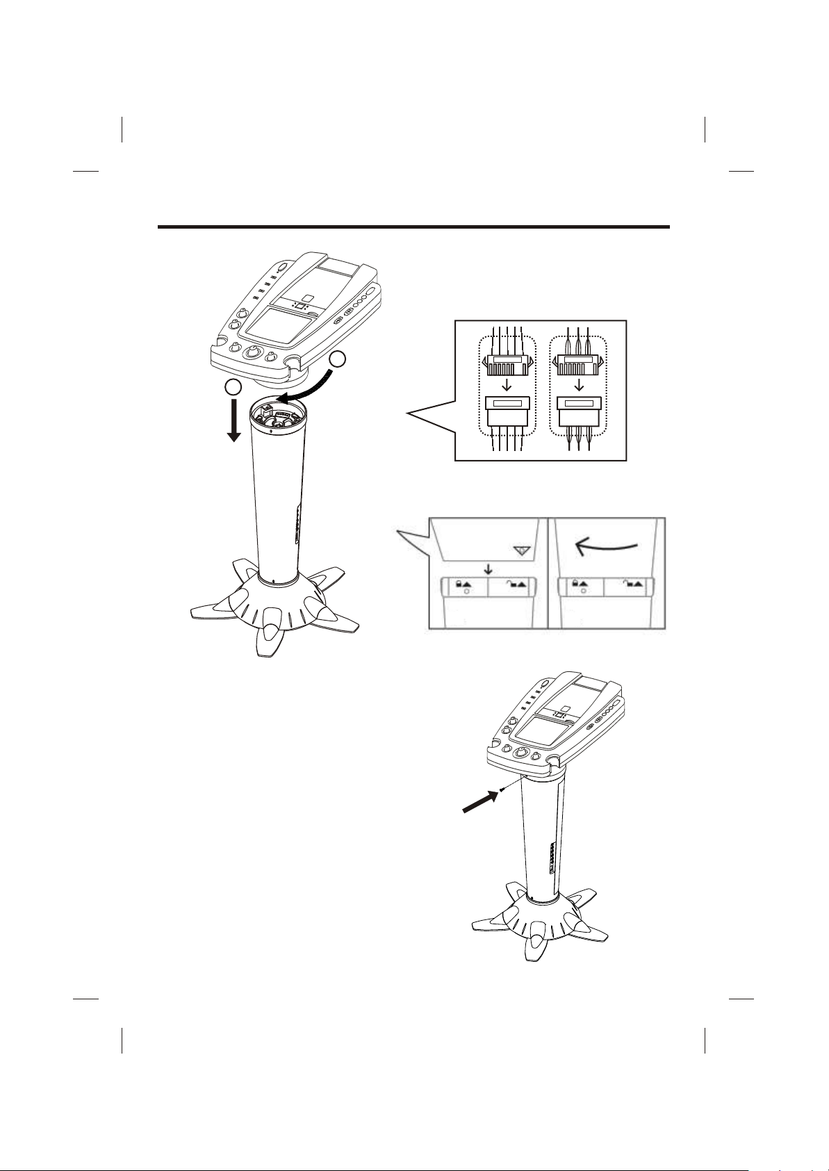
INSTALLATION
STEP 3
3. Join the control panel (top) into the speaker
(middle) according to the installation
illustration.
STEP 4
2
1
A
A B
A B
B
Following the labels (A to A & B to B) to plug the
connectors.
4. Tighten a self tapping screw at the control
panel (top).
6
Page 8
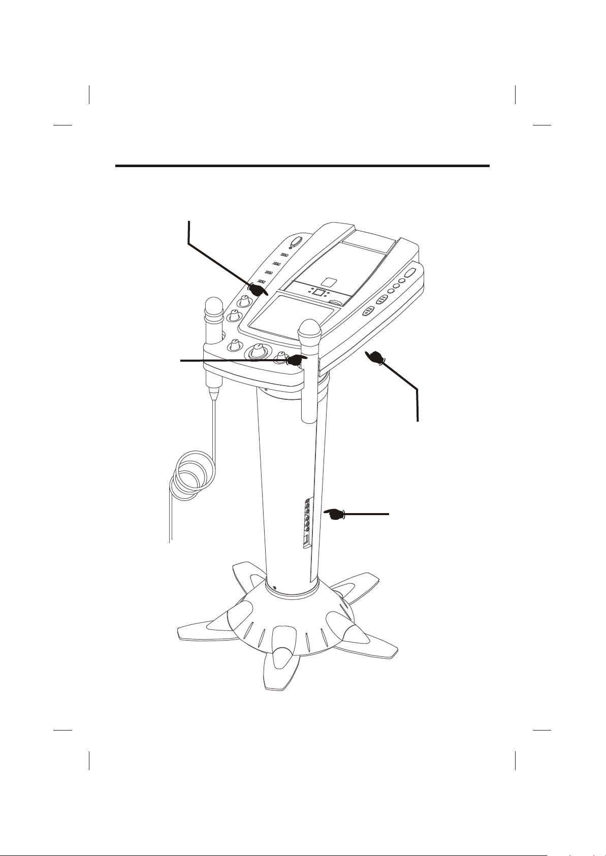
CONTROL LOCATIONS
See control locations as indicated on the next few pages.
FRONT VIEW
WIRELESS
MICROPHONE
REAR VIEW
SIDE VIEW
7
Page 9
CONTROL LOCATIONS
1
2
3
4
5
6
7
8
9
10
11
12
13
14
15
16
17
18
19
20
21
22
23
24
25
26
27
28
29
30
31
32
33
34
35
36
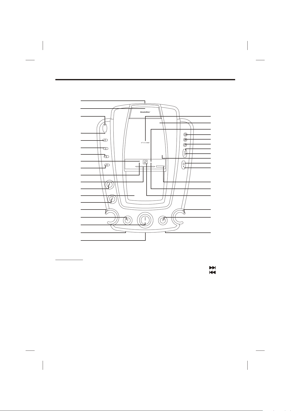
FRONT VIEW
1. Camera Lens Open 13. Monitor 25. RANDOM Button
Button 14. BALANCE Control 26. SKIP Button
2. Adjustable Camera Lens 15. MIC Holder 27. SKIP Button
3. ON/OFF Button 16. ECHO Control 28. OPEN/CLOSE Point
4. ON/OFF LED 17. MIC VOLUME Control 29. PLAY/PAUSE Button
5. Monitor Selector 18. MIC 1 Jack 30. STOP Button
6. Video Out Selector 19. HEADPHONE Jack 31. TUNING Knob
7. BAND Selector 20. Model Number 32. CDG LED
8. PROGRAM LED 21. CD Door 33. LED Display
9. Function Selector 22. PLAY/PAUSE LED 34. MIC Holder
10. REPEAT LED 23. PROGRAM Button 35. AUTO VOICE CONTROL
11. Dial Pointer 24. REPEAT Button 36. MIC 2 Jack
12. MASTER VOLUME
Control
8
Page 10

CONTROL LOCATIONS
37
38
REAR VIEW
37. BRIGHTNESS Control 39. VERTICAL HOLD Control
38. CONTRAST Control
9
39
Page 11

CONTROL LOCATIONS
44
40
41
42
43
SIDE VIEW
40. VIDEO IN Jack 44. Speaker
41. AUX INPUT Jack (R) 45. AUX INPUT Jack (L)
42. AUX OUTPUT Jack (L) 46. VIDEO OUT Jack
43. AC Power Cord Jack 47. AUX OUTPUT (R)
45
46
47
10
Page 12

CONTROL LOCATIONS
48
49
50
51
52
WIRELESS MICROPHONE
48. ON Position 51. LED Indicator
49. OFF Position 52. STANDBY Position
50. Battery Compartment
11
Page 13

MAKING THE CONNECTIONS
CONNECTING POWER
You can power the system from a standard AC outlet by using the supplied power cord.
CAUTION: The supplied AC power cord has a polarized plug that fits into the wall outlet only one
way. If the plug does not fit properly , turn it over and try again. Do not force it.
CONNECTING TO YOUR HEADPHONE
A headphone jack is provided for using headphones instead of the built-in speaker.
(Headphones are sold separately.)
CONNECTING TO YOUR TV
The Singing Machine provides a patch cord to give you the option of connecting your unit to an
external audio/sound system and video device. The patch cord has three RCA jacks at each
end; the White and Red are for left and right audio connections and the yellow is for connecting
the video.
Make sure that you have a CDG disc in the Singing Machine and playing when you are making
this connection. Y ou will know you have the proper settings on your TV or VCR as soon as you
see the Singing Machine logo or lyrics on the screen!
VIDEO CONNECTION
Please follow the steps below to display CDG lyrics on the TV screen:
(1) Locate the multicolored patch cords.
Connect video cable (yellow) to the Video Out of the side of the Singing Machine.
(2)
(3) Connect the other end of the Video Cable (yellow) to the Video Input on your TV or
VCR.
SIDE VIEW OF
SINGING MACHINE
VIDEO OUTPUT
(YELLOW JACK)
12
REAR VIEW OF TV
VIDEO IN
VIDEO INPUT
(YELLOW JACK)
R
AUDIO IN
L
Page 14

MAKING THE CONNECTIONS
If your television or VCR does not have the required Video Input, you will need an RF Modulator
(Radio Frequency Modulator), which connects through your TV Antenna or cable line and
serves as Video Input.
An RF Modulator can be purchased at almost any consumer electronics retailer. If you are
connecting the video from the Singing Machine to either a television or a VCR video input jack,
you must specify the source the TV or VCR is to display. Your TV or VCR us er guide can tell you
how to display the video signal from the ‘Video In’ jack.
If you don’t have the manual for your TV or VCR, we suggest calling the TV or VCR,
manufacturer’s customer service department. Only the manufacturer will be able to tell you very
quickly how to configure your TV or VCR to display the video signal coming from the ‘Video
Input’ jack.
D Note: Some projection TV sets do not properly display the standard blue background when
using most CDGs. If the background color is inconsistent or flashing, please try connecting your
Singing Machine to a standard tube television.
COMMON WA YS TO CONFIGURE YOUR TV OR VCR
Your Singing Machine is designed to connect to your TV the same way you would connect a
video camera, VCR or video game. The Singing Machine is constantly sending the video and
audio signals to the 'Video Out' and 'AUX OUT' jacks whenever you play a CDG . So, load a CDG
into your Singing Machine before you start making these connections. Y ou will see lyrics on the
TV screen as soon as you complete the set up correctly.
We refer to TV/VCR because manufacturers use very similar ways to connect TVs and VCRs
and you can connect your Singing Machine to a TV, VCR or satellite system (contact your
satellite company for instructions). The setup of your TV/VCR is the most difficult part of making
the connection for displaying your Singing Machine lyrics. In most homes, the TV has either a
cable connected or antennae in use. Once you connect your Singing Machine to the TV/VCR,
choose the correct input on your TV/VCR to display lyrics from The Singing Machine instead of
the usual input from the cable or antennae.
Check your TV/VCR user manual for the easiest way to setup your particular entertainment
system. If you don't have your manual you can always contact your TV/VCR manufacturer for
information either by phone or viewing their website for online assistance. We've listed below
the most common ways of setting up a TV/VCR:
In the setup menu for configuring the TV/VCR there may be an option on 'Input Selection'
(1)
where you may choose between 'Cable/Ant’, 'Video 1', or 'Video 2' etc. as the input source.
Try looking for a 'Video' channel between the highest channel and the lowest channel on
(2)
your TV or VCR. (i.e. Between 99 and 2 may be 'VIDEO' or 'INPUT' or 'GAME')
(3) Look for a button on the remote control for the TV/VCR you are connecting to that says
'VIDEO', 'VIDEO 1', 'Game', 'AUX', 'EXT', 'LINE1', 'LINE-IN' or occasionally the 'VCR'
button will display the Video input source.
13
Page 15

MAKING THE CONNECTIONS
CONNECTING A VIDEO COMPONENT FOR INPUT
Please follow the steps below to display CDG lyrics on the Singing Machine’s monitor from
another video source:
(1) Locate the multicolored patch cords.
(2) Connect video cable (yellow) to the Video In of the side of the Singing Machine.
(3) Connect the other end of the video cable (yellow) to the Video Output on another video
source such as a VCR.
(4) Set the Function Selector to AUX mode and the Monitor Selector to AUX.
(5) Adjust the BRIGHTNESS, CONTRAST and Controls at the back of
the Singing Machine to have the best picture quality.
SIDE VIEW OF
SINGING MACHINE
VERTICAL HOLD
REAR VIEW OF VCR
R
L
AUDIO OUT
VIDEO INPUT
(YELLOW JACK)
VIDEO OUT
VIDEO OUTPUT
(YELLOW JACK)
AUDIO CONNECTION
Connect the unit to your TV or home stereo system using the White and Red connections on the
supplied patch cord. Plug the white end of the patch cord into the white AUX OUT jack on the
unit. Plug the red end of the patch cord into the red AUX OUT jack on unit. Now connect the other
end of the cable’s white (left channel) and red (right channel) plugs to your TV or home stereo
system’s ‘AUDIO IN’ or ‘AUX IN’ jacks.
SIDE VIEW OF
SINGING MACHINE
REAR VIEW OF TV
R
VIDEO IN
AUDIO IN
L
AUX OUTPUT
R
(RED JACK)
AUX OUTPUT
L
(WHITE JACK)
14
AUDIO INPUT
R
(RED JACK)
AUDIO INPUT
L
(WHITE JACK)
Page 16

MAKING THE CONNECTIONS
CONNECTING AN AUDIO COMPONENT FOR INPUT
To connect another audio source (such as a Tuner , an AV Receiver or a VCR) so you can sing
along with its music, simply connect the Audio Output jacks (Red & White RCA jacks) to the
Singing Machine’s AUX IN L & R jacks.
SIDE VIEW OF
SINGING MACHINE
AUX INPUT
R
(RED JACK)
VIDEO OUT
AUX INPUT
L
(WHITE JACK)
ANOTHER
AUDIO COMPONENT
R
AUDIO OUT
AUDIO OUTPUT
R
(RED JACK)
AUDIO OUTPUT
(WHITE JACK)
L
L
MONITOR SELECTOR
! T o play a CDG disc, set the Monitor Selector to either CAMERA, CDG ,AUX or OFF mode.
! To display CDG lyrics on the Singing Machine’s monitor, set the Monitor Selector to CDG
mode.
! To display your image on the Singing Machine’s monitor, set the Monitor Selector to
CAMERA mode.
! To display a video signal from another A/V component, set the Function Selector to AUX
mode and Monitor Selector to AUX mode.
! T o turn off the monitor on the Singing Machine, set the Monitor Selector to OFF mode.
! Adjust the BRIGHTNESS, CONTRAST and VERTICAL HOLD Controls at the back of the
Singing Machine to have the best picture quality.
VIDEO OUT SELECTOR
! T o display image on the TV, set Function Selector to CDG or AUX position and set the Video
Out Selector to CAMERA mode.
! To display CDG lyrics on the TV, set Function Selector to CDG position and set the Video Out
Selector to CDG mode.
15
Page 17

CD OR CD+G OPERATION
D Warning - T apping or dropping the microphone while it is on can permanently damage
your microphone. Resist the urge to swing the microphone around by the cord!
PREPARA TION
! This unit is designed to play CD’s bearing the identification logo " ". If CD’s do not
conform to the CD standard, they may not play properly.
! Fingerprints and dust should be carefully wiped off with a soft cloth. Wipe in a straight motion
from the center of the disc to the outside edge.
! Never use chemicals, such as record cleaning sprays, antistatic sprays or fluids, benzene or
thinner to clean compact discs. These chemicals will permanently damage the plastic
surface of the disc.
! Always place the compact disc on the disc tray with the label facing upward. Compact discs
can be played on only one side.
! To remove a disc from it s storage case, press down on the center of the case and lift the disc
out, holding it carefully by the edges.
! Discs should be returned to their cases after use to protect them from dust and scratches.
! To prevent warping the disc, do not expose it to direct sunlight, high humidity or high
temperatures for extended periods of time.
! Do not apply paper or write anything on either side of the disc. The inks used in some felt-tip
pens may damage the surface of the disc.
PLAYING CD OR CD+G DISC
! Adjust MASTER VOLUME control on your unit, TV or audio system to a comfortable level.
! Adjust MIC/ECHO/BALANCE controls as needed to achieve the desired mix of music and
vocals through your TV or sound system.
! Do not press the disc cover of the CD compartment while it’s playing.
! Never place anything on top of the Singing Machine. Foreign objects can damage the unit.
! Do not apply excessive force to disc cover.
! Only place one disc in the CD compartment at a time.
TURNING POWER ON/OFF
! To turn on the karaoke center , press the ON/OFF button, the ON/OFF LED will light up.
! To turn of f the system, press the ON/OFF button again, the ON/OFF LED will turn off.
FUNCTION SELECT
Set the Function Selector to CDG .
MONITOR SELECT
! T o play a CDG, set Monitor Selector to either CAMERA, CDG , AUX or OFF mode.
! To display the CDG lyrics on the Singing Machine’s monitor, set Monitor Selector to CDG
mode.
! T o turn off the monitor on the Singing Machine, set Monitor Selector to OFF mode.
! Adjust the BRIGHTNESS, CONTRAST and VERTICAL HOLD Controls at the back of the
Singing Machine to have the best picture quality.
LOADING A DISC
! Lift the CD door at the OPEN/CLOSE point. Place a disc in the compartment with the printed
side facing upward and the shiny side facing down.
! Close the CD compartment. The LED window will display total number of track. (If no disc is
loaded, it will display “ ”).
(Refer to the Trouble Shooting Guide on page E21 if a disc is loaded but the total tracks
do not appear.)
16
Page 18

CD OR CD+G OPERATION
PLAY/PAUSE MODE
! To start playing, press the PLAY/PAUSE button. The first track [ ] and the PLAY/PAUSE
LED will be lit.
! To temporarily stop playing, press the PLAY/PAUSE button. The PLAY/PAUSE LED
Indicator will flash.
! T o resume play, press this button again.
PLEASE NOTE: Pressing pause when a CDG is playing may cause distorted lyrics on the
monitor. Any distortion will remain until the whole screen is refreshed during
an instrumental break or you stop the song and start it from the beginning.
STOP MODE
If the STOP button is pressed in the course of playing, the disc will cease to play. (The total
number of tracks will be shown on the LED window).
SKIP PLAY (For both CD and CDG discs.)
! During STOP mode, you can skip up or down to your desired track number by pressing a
SKIP button( - SKIP - ).
! T o resume playing the selected song, press PLAY/P AUSE button.
SEARCH (For audio CD disc only.)
When playing any audio CD, press and hold the SKIP button ( -SKIP- ). The CD will
search at high speed in the forward or backward direction. Normal play will continue when you
release the button.
REPEAT
! T o repeat the track currently playing, press the REPEAT button once. The REPEAT LED will
start to flash.
! To repeat all tracks, press the REPEAT button twice. The REPEAT LED will light up and stay
lit.
! To clear the repeat function. Press the REPEAT button again. The REPEAT LED will turn off.
PROGRAM
! Use this button to program and play back songs in a preselected order.
Step 1: Programming should be done in the stop mode only. Press the PROGRAM key
until the PROGRAM LED flashes, the track will read [ ].
Step 2: Press the double arrow keys ( -SKIP- ) to select a desired track.
Step 3: Press PROGRAM key to confirm entry. You can repeat the same steps up to a
maximum of 20 tracks.
Step 4: Press PLAY to activate PROGRAM.
! Press the STOP button to clear all the programmed entries.
17
Page 19

RADIO AND OTHER OPERATIONS
AM/FM RADIO
1. Press the ON/OFF button.
2. Switch Function Selector to RADIO position.
3. Switch Band Selector to either AM or FM radio position.
4. Turn tuning knob to select desired station as indicated on dial.
5. Adjust Master Volume to your pleasure.
6. To turn the radio off, set Function Selector to CDG or AUX position.
SING ALONG - RADIO
1. Follow operating instructions for AM/FM radio.
2. Connect the supplied Microphone to either one of the Mic input jacks.
3. Adjust Master Volume and Mic Volume. Your voice will be combined with the radio
station output and will be heard through the speaker.
Note: Echo effect cannot be activated in radio mode.
PUBLIC ADDRESS - USING A MICROPHONE
The unit can be used as a PA (Public Address System).
Public Address (PA) Operation Procedures
1. Connect the supplied Microphone to either one of the MIC input jacks.
2. Press the ON/OFF button to turn the unit on.
3. Set the Function Selector to AUX. Move the MIC VOLUME control to central position.
4. Move the ON/OFF switch located on the Microphone to ON position and speak or sing
to the Microphone. The Microphone sensitivity and loudness could be adjusted as
required by turning the MIC VOLUME control and/or MASTER VOLUME control.
5. To add depth or ambiance to your voice, adjust the ECHO control until the desired effect
is obtained.
Note: To prevent feedback or whistling from occurring, please be sure that the
microphone is not too close to the unit.
SMM-107 WIRELESS MICROPHONE OPERATIONS
1) Unscrewing the bottom of wireless microphone.
2) Place a 9V battery in the compartment as indicated by the polarity symbols (+ and -) marked
inside the compartment of the wireless microphone.
3) Replace the bottom of wireless microphone.
4) The switch on wireless microphone has three settings:
1. ON - The switch is in the top position. The microphone will function. The red indicator
light is on.
2. STANDBY - The switch is in the middle position. The microphone will not function. The
red indicator light is on.
NOTE: The purpose of this setting is to maintain a connection between the microphone
and the Singing Machine when moving around the area in which it is being used.
3. OFF - The switch is in the bottom position. The microphone will not function. The red
indicator light is off.
NOTE: T o ensure long battery life, please make sure that the wireless microphones is set to the
OFF position when not in use. When not in use for a long period of time, we recommend
that you remove the DC 9-V battery.
18
Page 20

WIRELESS MICROPHONE INFORMATION
Warning: Modifying, tampering and adjustment to this unit or replacement of any
transmitter component (crystal, semiconductor, etc.) to this unit that could result in a
violation of the rules.
FCC NOTICE
This wireless microphone system complies with Part 90 of FCC Rules. There is one frequency
available for the system. Y ou must get a licence for the frequency you plan to use before you use
the system.
Please look for this website http://wireless.fcc.gov/uls/ to apply the licence or phone to the
nearest FCC offices and contact them to get the necessary application. Licensibility depends on
how you will use the system.
For RF exposure
“IMPORTANT NOTE: To comply with the FCC RF exposure compliance requirements, no
change to the antenna or the device is permitted. Any change to the antenna or the device could
result in the system exceeding the RF exposure requirements.”
SAFETY INFORMATION
Your wireless microphone contains a low power transmitter. When the EUT is power on and it
sends out radio frequency (RF) signals. In August 1996, the Federal Communications
Commissions (FCC) adopted RF exposure guidelines with safety levels for wireless devices.
IMPORTANT
To maintain compliance with the FCC's RF exposure guidelines hold the transmitter and
antenna at least 1 inch (2.5 centimetres) from your face and speak in a normal voice, with the
antenna pointed up and away from the face. Ensure that the antenna is at least 1 inch (2.5
centimetres) from your body when you using your wireless microphone.
Use only the supplied antenna. Unauthorised antennas, modifications, or attachments could
damage the transmitter and may violate FCC regulations.
19
Page 21

CARE AND MAINTENANCE
POWER SWITCH
After using the unit, turn off the power by
pressing the ON/OFF button.
CLEANING THE UNIT
To clean the exterior of the unit, simply wipe
with a soft clean cloth moistened with plain
lukewarm water.
CLEANING THE CD LASER LENS
For the Best Results: Use a CD-lens cleaning
disc according to the cleaning disc
manufacturer instructions.
If a lens cleaning disc is not available, use a
clean, soft, dry cotton cloth to gently wipe the
small, glass, fish-eye laser lens located in the
CD players.
To prevent fire or shock hazard,
disconnect your stereo system
from the AC power plug when
cleaning.
COMPACT DISC
Handling Disc
Although the music tracks on the disc
are covered with a protective layer, it is
still advisable to treat the disc carefully.
Ensure that you always pick up discs by
the edge, and put them back in their
holders immediately after use.
CLEANING DISC
Cleaning will not normally be necessary.
However, should fingerprints, dust or
dirt appear, you can wipe them off with a
soft, lint-free cloth. Wipe the disc in a
straight line from center to edge. You
can moisten the disc first with ordinary
tap water if necessary.
NOTE: Do not use detergent
or abrasive cleaning agents
as they can damage the disc.
CD PLAYER
The player mechanism is fitted with selflubricating bearings and must not be
oiled or greased.
20
Page 22

TROUBLE SHOOTING GUIDE
If you have followed the instructions and are having difficulty operating the unit, locate the
PROBLEM in the left column below. Check the corresponding POSSIBLE CAUSE column to
locate and remedy the problem.
PROBLEM
No power when POWER
is on.
No power when plugged
in.
No sound.
No sound from TV/PA.
CD PLAYER
cannot work normally or
aai aa aaa
“ ”, “ ” , or “ ” are
displayed.
No sound - If audio is
going through home
stereo.
No sound - If audio is
going through TV or
VCR.
POSSIBLE CAUSE
No power plug connection at
the AC outlet.
The AC outlet may not have
power.
Volume control is set to
minimum.
The wrong function is
selected.
Volume control on TV set/PA
system is set to minimum.
TV set/PA system power is
OFF.
Patch cords are not
connected securely.
Disc is inserted upside
down.
Disc is dirty.
Disc is scratched.
Disc is warped.
A nonstandard disc is
inserted.
Moisture has formed inside
the CD deck.
Singing Machine needs to be
reset.
Source Selection on your
stereo is not set properly.
Improper Connection to
stereo system or PA.
Patch cords are not
connected securely.
Source Selection on TV or
VCR is not correct.
Patch cords are not
connected securely.
SOLUTION
Insert the power plug into the AC
outlet.
Check the outlet with a working
lamp or other electrical appliance.
Turn up the volume.
Select the correct function.
Turn up the volume at TV set/PA
system.
Turn on the power at TV set/PA
system.
Ensure white and red patch cords
are securely inserted into both
The Singing Machine and the
TV/PA system.
Insert disc correctly.
Wipe clean with soft cloth.
Use a new disc.
Use a new disc.
Only use discs bearing standard
logo as described on page E16.
Wait about 20 to 30 minutes to let
it dry out.
Disconnect the machine from
power source for 30 seconds.
Select AUX IN as the source for
your home stereo.
Follow direction on page E14 for
connecting to a home stereo
system.
Ensure white and red patch cords
are securely inserted into both
The Singing Machine and the
home stereo system.
Follow directions on page E13 for
“Making the Connections”.
Ensure white and red patch cords
are securely inserted into both
The Singing Machine and the
TV/VCR.
21
Page 23

TROUBLE SHOOTING GUIDE
PROBLEM
No song lyrics appear
on TV screen.
While playing CDG and
singing with the
microphone, the music
or vocal cuts out.
Picture is jumping up.
No image display on
Singing Machine’s
monitor when
attempting to use
camera.
Image is blurry.
POSSIBLE CAUSE
Video cable is not connected
properly to the TV.
Source selector on TV is not
set to VIDEO.
TV does not have video line
input.
A CDG is loaded but the
CDG indicator is not lit.
Balance is not adjusted
properly.
AVC is activated to
Maximum.
Playing music only track.
VERTICAL HOLD Control is
not set correctly.
The Camera Lens is down.
MONITOR Selector is not
set properly.
Lens cap is on. Remove lens cap.
Brightness control not
adjusted properly on Singing
Machine.
Camera has not warmed up.
Camera lens is dirty.
Camera lens is out of focus.
Connect the video cable to the
Singing Machine’s VIDEO OUT
and to the TV VIDEO IN.
Using your TV remote to select
VIDEO input or select the proper
VIDEO input on the TV itself.
(Refer to page E13 under
Common ways to configure your
TV or VCR)
Connect from VIDEO OUT of the
system to the VIDEO IN of your
VCR or connect to an RF
Modulator and then to the TV
cable input. Refer to “Making the
Connections” on page E13.
Check the disc to be sure it is a
CDG. (See page E24 for details.)
Check disc to be sure it is clean.
(See page E20 for cleaning
instructions.)
Adjust balance to mid point.
Adjust AVC to Minimum.
Play track that includes music and
vocal.
Adjust the VERTICAL HOLD
Control.
Lift up a Camera Lens.
Set MONITOR Selector to
CAMERA mode.
Adjust Brightness control on
Singing Machine.
Wait a minute for the camera to
warm up.
Clean the camera lens.
Adjust the lens of the camera by
slightly rotating either left or right
until the display is clear. Do not
overturn the lens.
SOLUTION
22
Page 24

SPECIFICATIONS
AUDIO SECTION:
OUTPUT POWER (MAXIMUM)
OUTPUT IMPEDANCE
CD PLAYER SECTION:
FREQUENCY RESPONSE
SIGNAL - TO - NOISE RATIO
WOW AND FLUTTER
D - A CONVERSION
NUMBER OF PROGRAMS
SAMPLING SYSTEM
MONITOR SECTION
RADIO SECTION:
AM FREQUENCY RANGE
FM FREQUENCY RANGE
7 WATTS (RMS)
6 OHMS
100 Hz - 20 kHz (+/-3 dB)
50 dB (A-WTD)
IMMEASURABLE
1-BIT DAC
20 STEPS RANDOM ACCESS PROGRAMMING
8 TIMES OVER SAMPLING
7” BLACK AND WHITE TV MONITOR
NTSC SYSTEM
220 LINE RESOLUTION
530-1710 kHz
88-108 MHz
MICROPHONE
POWER SECTION AC 110V-120V~60Hz
DIMENSIONS (H x W x D) 37.5 x 17.7 x 17.1 Inches / 95.2 x 45.0 x 43.5 cm
WEIGHT 16.4 lbs / 7.4 kgs
ACCESSORIES
Specifications are typical, individual units might vary. They are subject to continuous
improvement without notice and without incurring any obligation.
-74 dB 600 OHMS IMPEDANCE WITH
6.3mm DYNAMIC MICROPHONE
1. PRE-RECORDED KARAOKE CD+G DISC
2. AV CABLE
3. WIRELESS MICROPHONE
4. SCREWS
5. AC POWER CORD
23
Page 25

THE SINGING MACHINE KARAOKE GLOSSARY OF TERMS
In addition to all of the terminology associated with consumer electronics products, a few
additional terms are used almost exclusively in karaoke. These terms are meant to familiarize
you with the world of Karaoke. The features listed below may not necessarily pertain to the
particular model Singing Machine that you have. The following are some brief explanations of
karaoke terms:
Echo:
Echo adds depth and resonance to a singer's voice, without affecting the music. This echo is
produced by creating minor controlled feedback in the singer's voice.
Multiplex:
Our multiplex recordings contain 2 copies of the same song. One version is a stereo recording of
the song without the lead singer. The second version is recorded with the music and
background vocals on the left channel and the lead singer recorded on the right channel. This
‘split track’ recording allows you to control the volume of the lead singer by adjusting the balance
control. You c an sing a duet with the lead singer or use the lead singer as a guide as you learn
the song, gradually fading them out with the balance control until you are able to sing the song
on your own.
Auto Voice Control (A.V .C.):
When the A VC function is activated, the vocals on a multiplex recording are eliminated as soon
as the singer begins singing into the microphone. When the singer stops singing, the vocals on
the multiplex recording are automatically re-activated. This useful function is used primarily
during practice sessions while a singer is learning a song. Please note that the AVC function
only works with multiplex recording and not with standard audio recordings.
Pitch Control:
This function controls pitch of music by controlling the speed at which a cassette tape plays
back. By increasing the speed of the tape, the music sounds higher (sharp). By slowing the tape
speed, the music sounds lower (flat).
Key Controller:
Key Controller changes the key of the CD/CDG music (+ or - steps) to adjust to the singer’s
voice.
CDG:
This is an acronym for Compact Disc plus Graphics. You will also see variations CD+G, and
CD+Graphics. This is a regular audio CD with information stored on a data track simultaneous
to music. In laymen's terms, CDG has a video output for simple graphics (not full motion video).
In the case of karaoke, the graphics function is used to store song lyrics, and display the lyrics in
synch with music. In most cases, CDG software displays lyrics which change color as they are
to be sung. A regular television is all that is required to display CDG lyrics.
NOTE - CDG is a particular type of compact disc encoding system that is different from VCD or
DVD. Your Singing Machine can decode standard audio compact discs and CDG discs. It will
not read VCD or DVD encoded discs.
Standard audio discs and cassette tapes will not display lyrics on your TV. Audio CDs do not
contain the software necessary to display lyrics.
24
Page 26

Page 27

Page 28

The Singing Machine Company, Inc.
988-0411-ENG01
6601 Lyons Road, Bldg. A7, Coconut Creek, FL33073-9902, USA.
TEL: (954) 596-1000 FAX: (954) 596-2000
VISIT OUR WEBSITE www.singingmachine.com
PRINTED IN CHINA
 Loading...