

The Singing Machine SMDigital iSM-370 Instruction Manual
SAFETY PRECAUTIONS
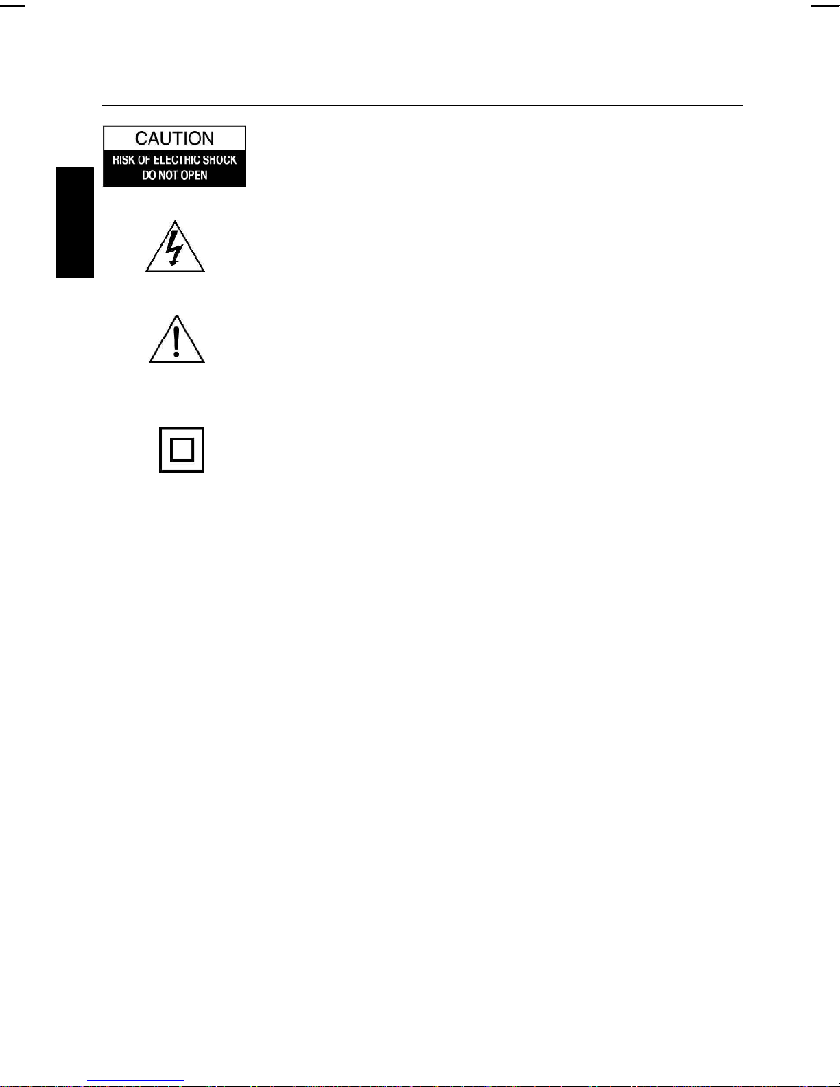
WARNING: TO REDUCE THE RISK OF ELECTRIC SHOCK, DO NOT
REMOVE COVER (OR BACK). NO USER-SERVICE- ABLE PARTS
INSIDE, REFER SERVICING TO QUALIFIED SERVICE PERSONNEL.
The lightning flash with arrowhead symbol, within an equilateral
triangle, is intended to alert the user to the presence of uninsulated
“dangerous voltage” within the product’s enclosure that may be of
ENGLISH
sufficient magnitude to constitute a risk of electric shock to
persons.
The exclamation point within an equilateral triangle is intended to
alert the user to presence of important operating and maintenance
(servicing) instructions in the literature accompanying the appliance.
The symbol for Class II (Double Insulation)
WARNING
To prevent fire or shock hazard, do not exose this appliance to rain or moisture.
The apparatus should not be exposed to dripping or splashing and no objects filled with liquids,
such as vases, shall be placed on the apparatus.
The ventilation should not be impeded by covering the ventilation openings with items, such as
newspapers, table-cloths, curtains, etc.
No naked flame sources, such as lighted candles, should be placed on the apparatus.
The mains plug is used as the disconnect device, the disconnect device should remain readily
operable.
In order to disconnect the apparatus from the mains completely, the mains plug should be disconnected from the mains socket outlet completely.
CAUTION
TO PREVENT ELECTRIC SHOCK, DO NOT USE THIS (POLARIZED) PLUG WITH ANY EXTENSION
CORD, RECEPTACLE OR OTHER OUTLET UNLESS THE PLUG CAN BE FULLY INSERTED
WITHOUT EXPOSING ANY PARTS OF THE BLADES.
TO PREVENT ELECTRICAL SHOCK, MATCH WIDE BLADE PLUG TO WIDE SLOT FULLY INSERT.
FCC IMPORTANT
Since alarm clock radio circuitry may cause interference with other radio tuners nearby, switch
this player off when not in use or move it away from an affected radio tuner.
This device complies with Part 15 of the FCC Rules. Operation is subject to the following two
conditions: (1) This device may cause harmful interference, and (2) this device must accept any
interference received, including interference that may cause undesirable operation.
E 1

SAFETY PRECAUTIONS
Warning: Changes or modifications not expressly approved by the party responsible for
compliance could void the user's authority to operate the equipment.
NOTE: This equipment has been tested and found to comply with the limits for a Class B digital
device, pursuant to Part 15 of the FCC Rules. These limits are designed to provide reasonable
protection against harmful interference in a residential installation. This equipment generates, uses
and can radiate radio frequency energy and, if not installed and used in accordance with the
instructions, may cause harmful interference to radio communications. However, there is no
guarantee that interference will not occur in a particular installation. If this equipment does cause
harmful interference to radio or television reception, which can be determined by turning the
equipment off and on, the user is encouraged to try to correct the interference by one or more of
the following measures:
• Reorient or relocate the receiving antenna.
• Increase the separation between the equipment and receiver.
• Connect the equipment into an outlet on a circuit different from that to which the
receiver is connected.
• Consult the dealer or an experienced radio / TV technician for help.
This Class B digital apparatus complies with Canadian ICES-003.
ENGLISH
SAFETY CERTIFICATION
This alarm is made and tested to meet safety standards of the FCC, requirements and
compliance with safety performance of the U.S. Department of Health and Human Services, and
also with FDA Radiation Performance Standards 21 CFR Subchapter J.
E 2
IMPORTANT SAFETY INSTRUCTIONS
1. Read these instructions.
2. Keep these instructions.
3. Heed all warnings.
4. Follow all instructions.
5. Do not use this apparatus near water.
6. Clean only with a dry cloth.
ENGLISH
7. Do not block any of the ventilation openings.
Install in accordance with manufacturer’s instructions.
8. Do not install near any heat source such as radiators, heat registers, stoves, or other
apparatus (including amplifiers) that produce heat.
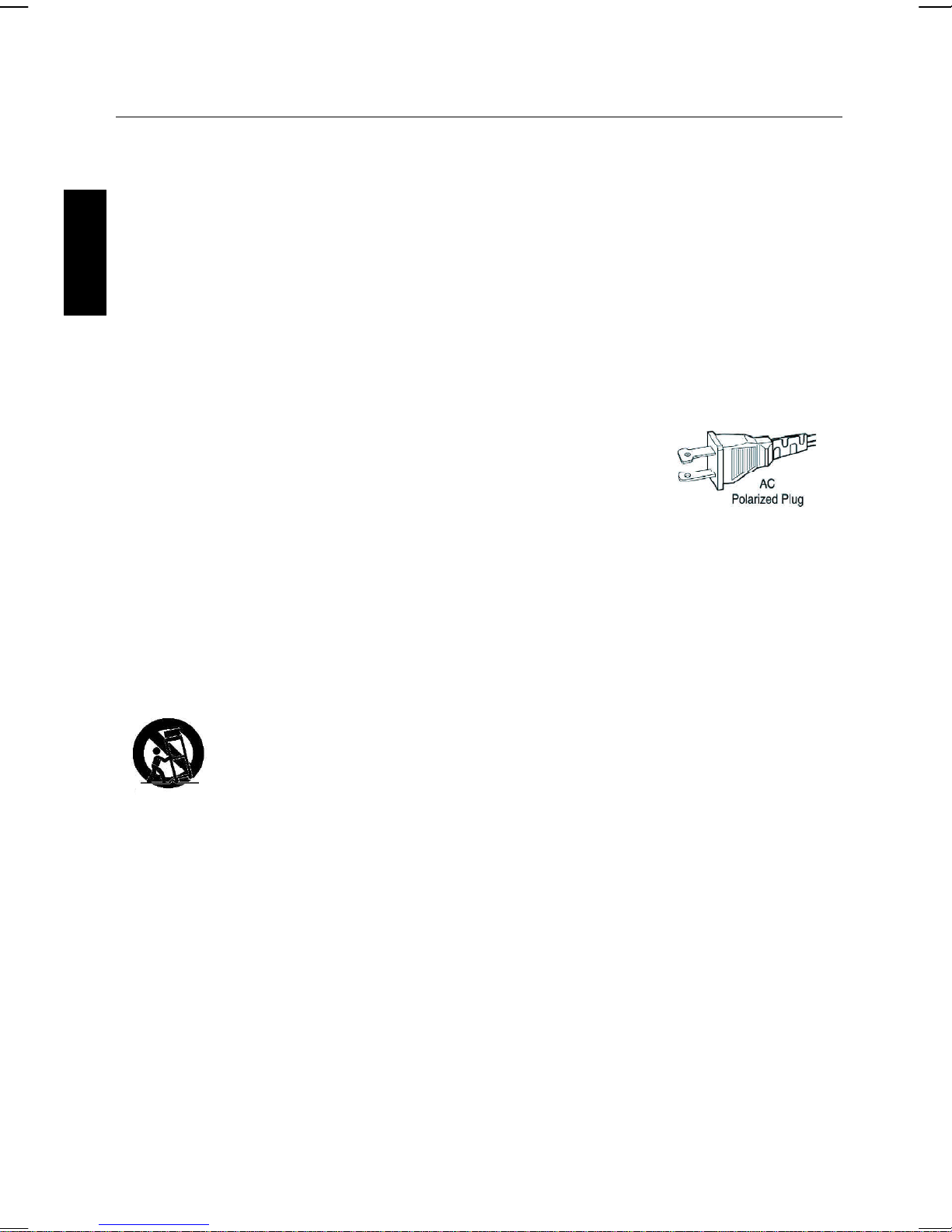
9. Do not defeat the safety purpose of the polarized or
grounding-type plug. A polarized plug has two blades with
one wider than the other. A grounding type plug has two
blades and a third grounding prong. The wide blade or the
third prong are provided for your safety. If the provided plug
does not fit into your outlet, consult an electrician for
replacement of the obsolete outlet.
10. Protect the power cord from being walked on or pinched, particularly at plugs, convenience receptacles, and the point where they exit from the apparatus.
11. Only use attachments/accessries specified by the manufacturer.
12. Use only with a cart, stand, tripod, bracket, or table specified by the
manufacturer or sold with the apparatus. When a cart is used, use caution
when moving the cart/apparatus combination to avoid injury from tipover.
13. Unplug this apparatus during lightning storms or when unused for long periods of time.
14. Refer all servicing to qualified service personnel. Servicing is required when the appara-
tus has been damaged in any way, such as if the power-supply cord or plug is damaged, liquid
has been spilled or objects have fallen into the apparatus, or when the apparatus has been
exposed to rain or moisture, does not operate normally, or has been dropped.
E 3

INTRODUCTION
Your Karaoke System will provide you with many years of fun and entertainment. It can let you
be the “star” as you sing along with your favorite recordings and hear your voice with the
music through the system’s speaker.
This karaoke center is easy to use, yet full of features with a compact design. After just a few
simple instructions, you will become an expert. Before you use your unit, please glance through
this manual to familiarize yourself with all the features available and the sections of the manual
that describe their operation. Next, go to the section for the specific operation you wish to
perform.
For your easy reference, listed here are some of the main features of this karaoke center:
Lyrics on TV screen - displays the lyrics with the tempo of the music when playing CD+G
discs.
Auto Voice Control (A.V.C.) - allows you to replace the original singer’s voice with your own
voice when any prerecorded, multiplex disc is played.
ENGLISH
Echo Control - allows you to add an echo to enrich your voice for a concert hall effect.
Built-In Speaker - allows you to share the music with your family or friends.
Audio Output Jacks - allows you to connect another audio output component, such as an
equalizer/booster or a PA system.
Headphone Jacks - allows you to connect headphones as an alternative for listering through
the system’s built-in speaker.
iPod Docking Station - the iPod docking station is compatible with a variety of iPod models,
the cradle audio system for the iPod allows you to simply plug in and press play to stream the
entire library of stored music from your iPod music player. Your karaoke system will provide a
pleasurable sound.
E 4
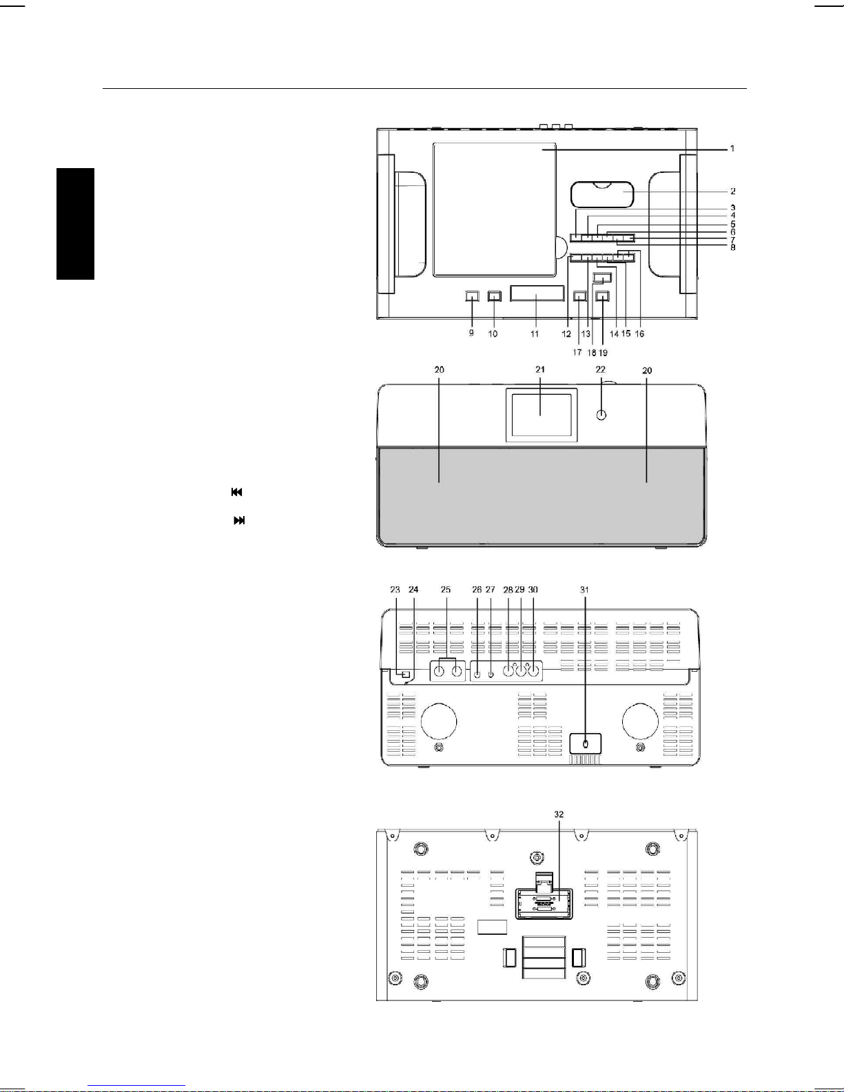
LOCATION OF CONTROLS
MAIN UNIT
1. CD Door
2. Cover for iPod dock
3. SLEEP Button
4. BAND AM/FM Button
5. CLOCK ADJ./PROGRAM Button
ENGLISH
6. Preset -/REPEAT Button
7. FUNCTION Button
8. Preset +/RANDOM Button
9. WAKE TO Button
10. ALARM ON/OFF
11. SNOOZE/DIMMER Button
12. PLAY/PAUSE/ENTER Button
13. STOP/FM MODE Button
14. TUNING -/SKIP /MINUTE Button
15. TUNING +/SKIP /HOUR Button
16. VOLUME -/+ Buttons
17. ALARM 1 Button
18. STANDBY/ON Button
19. ALARM 2 Button
20. Speakers
21. Display
22. Remote Sensor
23. AM ANT. Jack
24. FM ANT.
25. MIC Jacks
26. PHONES Jack
27. AUX IN Jack
28. VIDEO OUTPUT Jack
29. AUDIO OUTPUT (L) Jack
30. AUDIO OUTPUT (R) Jack
31. AC mains cord
32. Clock Batteries Back-up
Compartment
E 5
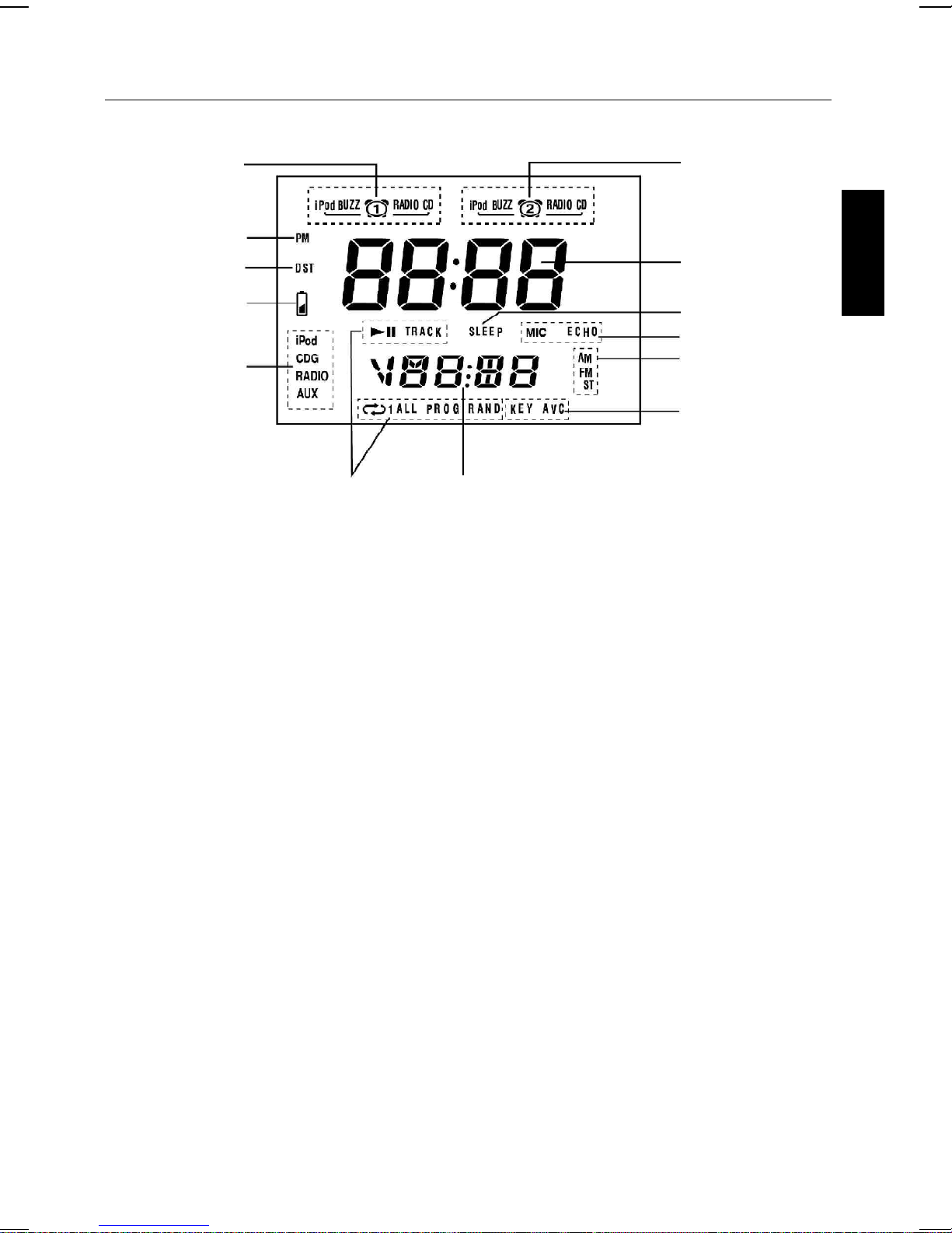
LCD DISPLAY
ALARM 1 Armed
PM Indicator
DST Indicator
Low Battery Indicator
Function Indicator
CD/CDG
function Indicator
Radio Frequency
Volume Level Display
ALARM 2 Armed
TIME/ALARM Display
SLEEP Indicator
MIC/ECHO Indicator
AM/FM Indicator
KEY/AVC Indicator
ENGLISH
E 6
LOCATION OF CONTROLS
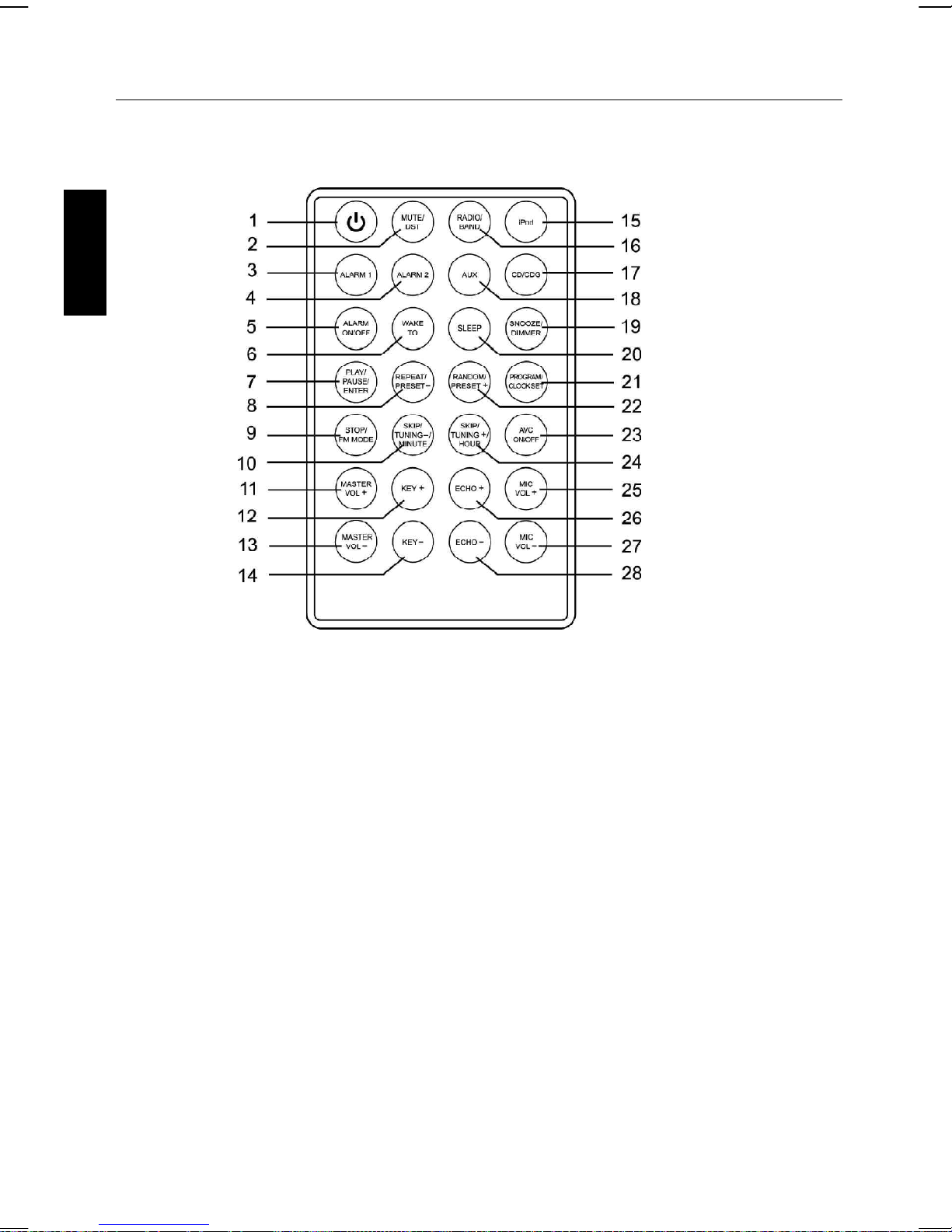
REMOTE CONTROL
ENGLISH
1. STANDBY/ON Button
2. MUTE/DST Button
3. ALARM 1 Button
4. ALARM 2 Button
5. ALARM ON/OFF Button
6. WAKE TO Button
7. PLAY/PAUSE/ENTER Button
8. REPEAT/PRESET - Button
9. STOP/FM Mode Button
10. SKIP/TUNING -/MINUTE Button
11. MASTER VOL + Button
12. KEY + Button
13. MASTER VOL - Button
14. KEY - Button
15. iPod Button
16. RADIO/BAND Button
17. CD/CDG Button
18. AUX Button
19. SNOOZE/DIMMER Button
20. SLEEP Button
21. PROGRAM/CLOCK SET Button
22. RANDOM/PRESET + Button
23. AVC ON/OFF Button
24. SKIP/TUNING +/HOUR Button
25. MIC VOL + Button
26. ECHO + Button
27. MIC VOL - Button
28. ECHO - Button
E 7
LOCATION OF CONTROLS
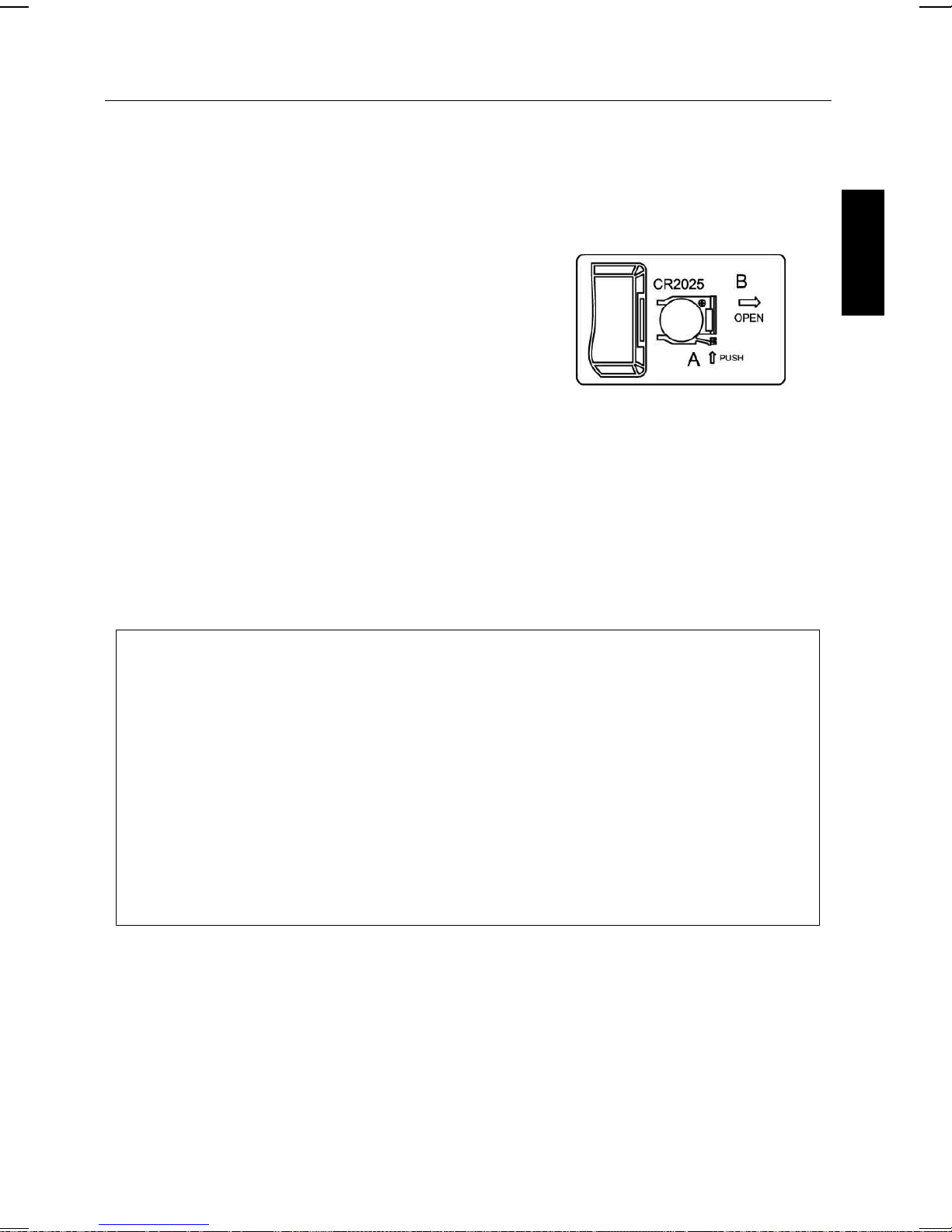
REMOTE CONTROL BATTERY
USING THE REMOTE CONTROL UNIT
Install / Replace the Remote Control Battery
The remote control battery is already installed at the factory. When the remote control stops
operating, replace the battery with a new one.
1. The battery door is located on the back end of the unit.
2. Squeeze notched tab A while pulling battery door latch
B to release the battery door latch and take out the
battery holder.
3. Insert “CR2025” 3-volt lithium battery. Make sure the
polarity (the + and - side of the battery) is correct.
4. Replace the battery holder back in the remote control.
NOTE: Please remove the tag before the first time use.
ENGLISH
BATTERY PRECAUTIONS
Follow these precautions when using batteries in this device:
1. Do not attempt to recharge, short-circuit, disassemble, heat or throw the batteries into a
fire.
2. Do not mix old and new batteries.
3. Do not mix alkaline, standard (carbon-zinc), or rechargeable (nickel cadmium) batteries.
4. If the device is not to be used for a long period of time, remove the batteries to
prevent damage or injury from possible battery leakage.
5. Do not try to recharge batteries not intended to be recharged; they can overheat and
rupture. (Follow battery maufacturer’s directions.)
6. Dispose of batteries properly in accordance with local laws.
E 8
MAKING THE CONNECTIONS
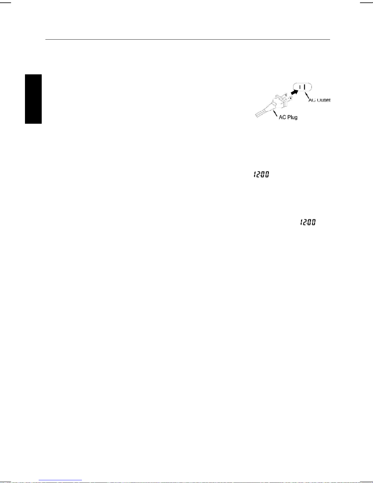
POWER SOURCE
Insert the AC plug (with the 2 blades) into a conveniently located AC outlet having 110V120V~60Hz.
NOTE: The AC plug supplied with the unit is polarized to help
minimize the possibility of electric shock. If the AC plug does
not fit into a nonpolarized AC outlet, do not file or cut the wide
blade. It is the user’s responsibility to have an electrician
replace the obsolete outlet.
ENGLISH
MAIN POWER SUPPLY
• Check that the power voltage as shown on the type plate corresponds to your local power
voltage. If it does not, consult your dealer or service organization.
• Connect the power cord to the wall outlet of AC power supply. As soon as you insert the
power plug into the wall outlet, the display time will flash and show (Assuming there
is no battery for backup or battery is weak). Please see page E13 how to set the correct
time.
POWER FAILURE
If power failure occurs, the unit will switch off. As soon as the power supply returns, will
flash and display, indicating that you must reset the correct time.
BATTERY BACK-UP SYSTEM
• Insert 2 “AA” batteries (not included) into the battery compartment. In the event of a power
failure, the batteries will provide sufficient power to maintain the time. When AC power is
restored, the correct time will be restored and will not require resetting.
• Neither the display nor the unit will operate until the unit is connected to an AC outlet.
BATTERY WILL ONLY RESTORE CLOCK SETTINGS WHEN AC POWER IS RESTORED.
• Replace the battery once per year. The service of the battery depends on how often and for
how long the power supply fails. This varies from one region to another.
Note:
1. Always check the time and reset if necessary when first time connecting AC mains or after
a power failure.
2. The 2 batteries are used for backing up the time in case of AC mains power failure, under this
circumstance, do not attempt to operate the unit, otherwise, battery service life will be
reduced.
E 9
MAKING THE CONNECTIONS
CONNECTING TO YOUR TV
The karaoke system includes RCA cords to provide you the option of either connecting an
external audio/sound system and/ or video device. The cords have three RCA plugs at each
end; the White and Red are for left and right audio connections and the yellow is for connecting
the video.
Make sure that you have a CDG disc in the unit and playing when you are making this
connection. You will know you have the proper settings on your TV or VCR as soon as you see
the SMDigital logo or lyrics on the screen!
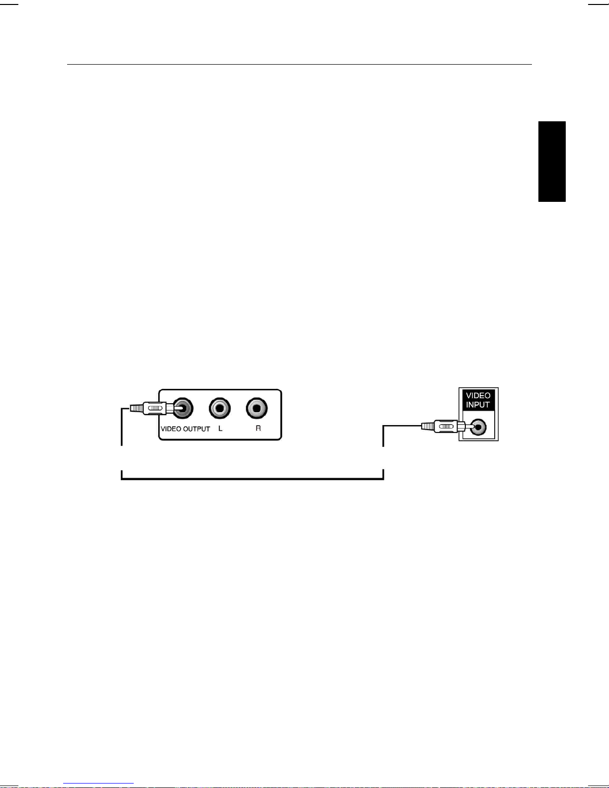
VIDEO CONNECTION
Please follow the steps below to display CDG lyrics, iPod photos/movies on the TV screen:
(1) Locate the multicolored patch cords.
(2) Connect video cable (yellow) to the Video Out of the back of the karaoke system.
(3) Connect the other end of the video cable (yellow) to the Video Input on your TV or VCR.
ENGLISH
VIDEO OUTPUT
(Yellow Jack)
REAR VIEW OF
KARAOKE SYSTEM
REAR VIEW OF TV
VIDEO INPUT
(Yellow Jack)
E 10

MAKING THE CONNECTIONS
If your television does not have the required Video Input, you will need an RF Modulator (Radio
Frequency Modulator), which connects through your TV Antenna or cable line and serves as
Video Input.
An RF Modulator can be purchased at almost any consumer electronics retailer. If you are
connecting the video from the karaoke system to either a television or a VCR video input jack,
you must specify the source the TV or VCR is to display. Your TV or VCR user guide can tell
you how to display the video signal from the ‘Video In’ jack.
ENGLISH
If you don’t have the manual for your TV or VCR we suggest calling the TV or VCR
manufacturer’s customer service department. Only the manufacturer will be able to tell you very
quickly how to configure your TV or VCR to display the video signal coming from the ‘Video
Input’ jack.
* Note: Some projection TV sets do not display the standard blue background used on most
CDGs properly. If the background color is inconsistent or flashing, please try connecting your
karaoke system to a standard tube television.
COMMON WAYS TO CONFIGURE YOUR TV OR VCR
Your karaoke system is designed to connect to your TV the same way you would connect a
video camera, VCR or video game. The karaoke system is constantly sending the video and
audio signals to the ‘Video Out’ and ‘AUX OUT’ jacks whenever you play a CDG. So, load a CDG
into your karaoke system before you start making these connections. You will see lyrics on the
TV screen as soon as you get the setup completed correctly.
We refer to TV/VCR because manufacturers use very similar ways to connect TVs and VCRs
and you can connect your karaoke system to a TV, VCR or satellite system. The setup of your
TV/VCR is the most difficult part of making the connection for displaying your karaoke system
lyrics. In most homes, the TV has either a cable connected or antennae in use. Once you
connect your karaoke system to the TV/VCR, you must ‘tell’ your TV/VCR to display the input
from the karaoke system instead of the usual input from the cable or antennae.
Check your TV/VCR user manual for the easiest way to setup your particular entertainment
system. If you don’t have your manual you can always call your TV/VCR manufacturer for that
information or try hitting their website for online assistance. We’ve listed below the most
common ways of setting up a TV/VCR:
(1) In the setup menu for configuring the TV/VCR there may be an option on ‘Input Selection’
where you may choose between ‘Cable/Ant.’, ‘Video 1’, or ‘Video 2’ etc. as the input
source.
(2) Try looking for a ‘Video’ channel between the highest channel and the lowest channel on
your TV or VCR. (i.e. Between 99 and 2 may be ‘VIDEO’ or ‘INPUT’ or ‘GAME’)
(3) Look for a button on the remote control for the TV/VCR you are connecting to that says
‘VIDEO’, ‘VIDEO 1’, ‘Game’, ‘AUX’, ‘EXT’, ‘LINE1’, ‘LINE-IN’ or occasionally the ‘VCR’
button will display the Video input source.
E 11
MAKING THE CONNECTIONS
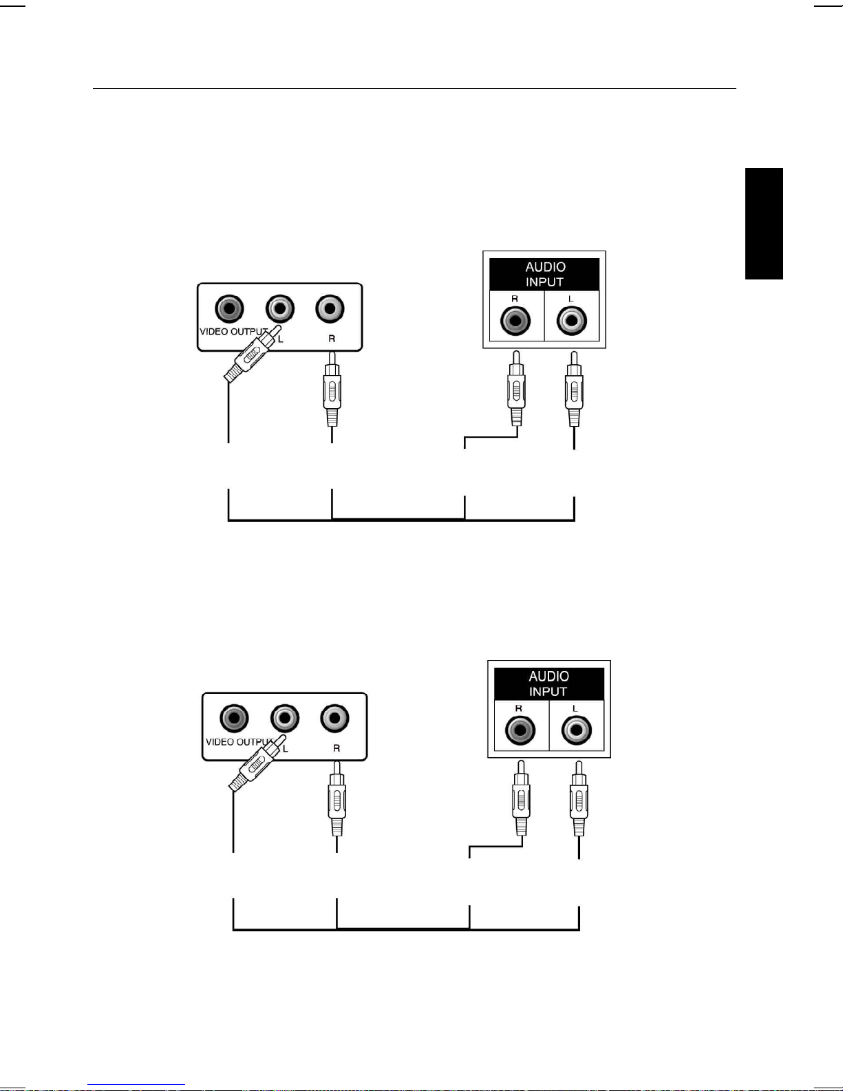
AUDIO CONNECTION
Connect the unit to your TV or home stereo system using the White and Red connections on the
supplied patch cord. Plug the white end of the patch cord into the white AUDIO OUT jack on the
unit. Plug the red end of the patch cord into the red AUDIO OUT jack on unit. Now connect the
other end of the cable’s white (left channel) and red (right channel) plugs to your TV or home
stereo system’s ‘AUDIO IN’ or ‘AUX IN’ jacks.
REAR VIEW OF TV
REAR VIEW OF
KARAOKE SYSTEM
ENGLISH
AUDIO OUTPUT
L
(White Jack)
AUDIO OUTPUT
R
(Red Jack)
AUDIO INPUT
R
(Red Jack)
AUDIO INPUT
L
(White Jack)
FOR CONNECTING AN AUDIO COMPONENT FOR OUTPUT
To connect an audio component (such as a power amplifier or PA system amplifier) so you can
hear the system’s music & vocal through it, plug the audio component into the AUDIO OUT jacks.
ANOTHER AUDIO
REAR VIEW OF
COMPONENT
KARAOKE SYSTEM
AUDIO OUTPUT
L
(White Jack)
CONNECTING TO YOUR HEADPHONE
A headphone jack is provided for using headphones instead of the built-in speakers.
(Headphones are sold separately.)
WARNING: Excessive sound pressure from headphones can cause hearing loss.
AUDIO OUTPUT
R
(Red Jack)
AUDIO INPUT
(Red Jack)
E 12
AUDIO INPUT
R
L
(White Jack)

CLOCK/ALARM OPERATIONS
Operation
• Press the STANDBY/ON button of the unit once to turn on power of the system.
Adjusting the volume
You can adjust the volume on the unit.
Press VOLUME +/- until the desired volume is reached, and volume level is displayed on the
display.
ENGLISH
Setting the Clock
The LCD display for the clock time.
1. Press CLOCK ADJ. button and the time digits begin to flash on the display.
2. Press HOUR button to set the hour. Press and hold for more than 1 sec to enter fast setting.
3. Press MINUTE button to set the minutes. Press and hold for more than 1 sec to enter fast
setting.
4. Press CLOCK ADJ. button to confirm. The time digits stop flashing and the clock is set
and starting to run.
5. Press and hold the DST button on the remote to change the daylight saving time. DST on will
advance the time 1 hour. DST off will turn the clock back 1 hour.
Using the Alarm
Setting Alarm Time
1. The unit can set two Alarm Time.
2. Press and hold the ALARM 1 Button or ALARM 2 button until the display flashes. Press the
HOUR or MINUTE button until the desired alarm time is displayed. Remember to set the correct
AM or PM (an icon to the right of the time display is the PM indicator. There is no AM
indicator).
3. Press the WAKE TO button to select the radio, iPod, CDG or buzzer to wake to a
corresponding Wake icon will light up for the selected Wake sound.
4. Press the ALARM 1 button or ALARM 2 button (or ENTER button) again to exit the setting
mode. The alarm time and wake to mode are set.
5. Press ALARM ON/OFF to select activating ALARM 1, ALARM 2 or ALARM 1+ ALARM 2.
6. When ALARM armed, you can press ALARM ON/OFF to stop ALARM.
Note:
• Once you set the alarm time, the alarm will be automatically armed. The Alarm icon and Wake
icon will appear to indicate the alarm is armed. Will be automatically armed for 60 minutes.
• Make sure to adjust volume level for comfortable wake up volume.
• When the Alarm wake to “iPod” mode, if “iPod” not docked, alarm will activate Buzzer instead.
• When the Alarm wake to “CD” mode, if there is no Disc loaded, alarm will activate Buzzer
instead.
Resetting the Alarm for the Next Day
When the alarm is sounding, press the STANDBY/ON button to stop alarm and reset it for the
following day.
E 13

CLOCK/ALARM OPERATIONS
SNOOZE / DIMMER OPERATION
a) Press the SNOOZE/DIMMER button after the alarm sounds. The alarm will be silenced and will
come on again about 10 minutes later. Snooze can be pressed several times during the 1
hour alarm cycle.
b) During normal operation, press the SNOOZE/DIMMER button to control the brightnes of the
LCD display.
SLEEP
The unit has built-in sleep function. This function enables you to listen to the RADIO/iPod/CDG/
AUX at bedtime without having to get up to switch off. The system will automatically switch off
at the desired sleep time.
NOTE:
• The external equipment which connected to AUX of this system will not be switched off
automatically.
• Need to turn on the unit before setting the sleep function.
SLEEP time
The period when you listen to your RADIO/iPod/CDG/AUX before you fall asleep, is called the
sleep time. The clock radio has built-in 9 mode time, change sleep time cycle (-- 10 20 30
40 50 60 70 80 90). If you wish to set the sleep time for 30 minutes, proceed as
follows:
• Press the SLEEP button 3 times. 30 will appear on the display indicating and SLEEP
indicator is on that you have a sleep time of 30 minutes.
ENGLISH
E 14
iPod INSERTS
1. Please make sure to use the correct insert for your iPod that is properly docked into
the system, fail to do so may damage your iPod.
2. No insert is provided for the iPod shuffle model.
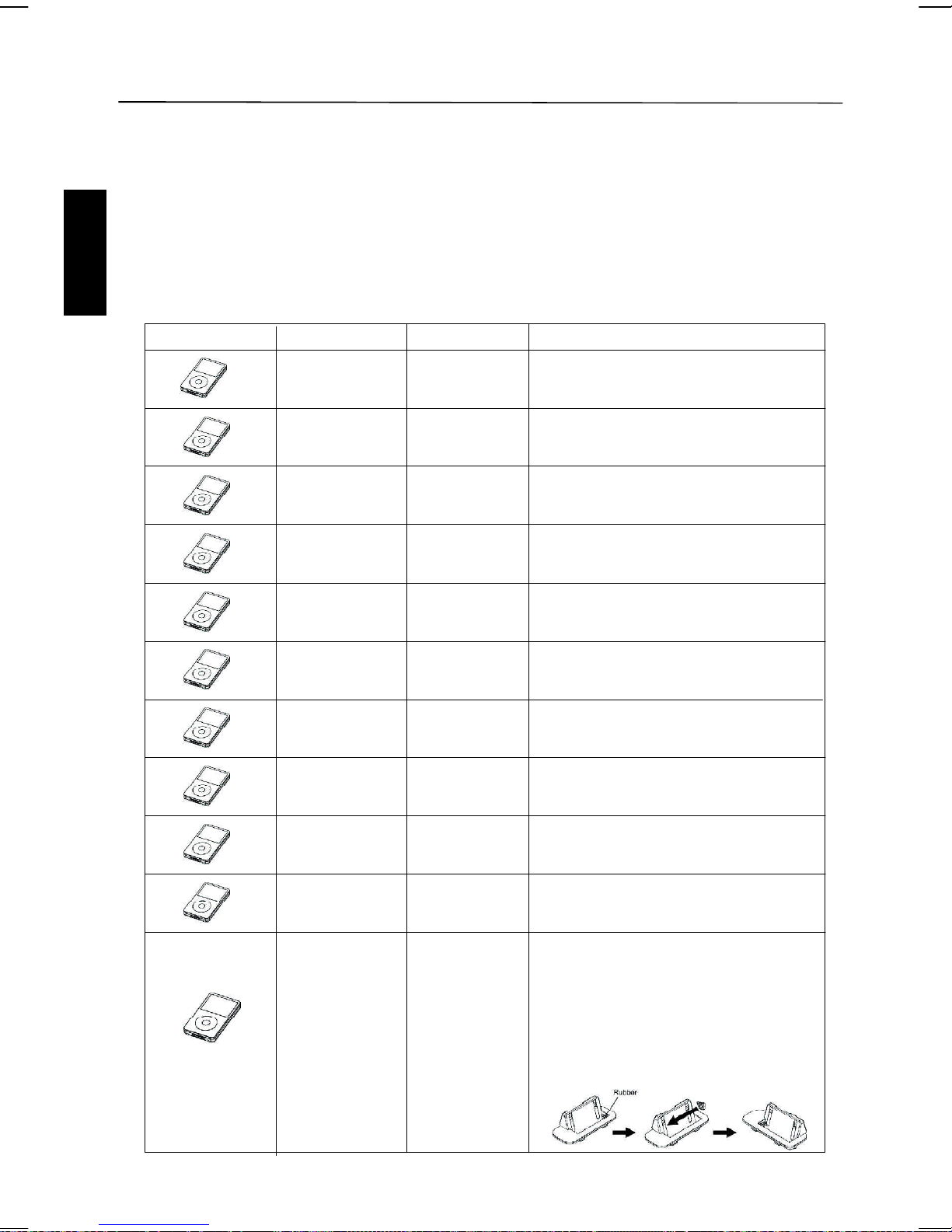
iPod Inserts
Your karaoke system comes with removable inserts to fit your iPod properly while docked. Each
insert carries a number to match your iPod. Please locate the correct one according to below
summary:
Refer to iPod OPERATION chapter to operate and charge the iPod player. (Except iPod shuffle.)
ENGLISH
iPod Type Memory Holder No.
iPod mini
iPod photo &
Color U2 iPod
iPod photo 40GB & 60GB Photo 40/60GB
iPod nano 2GB & 4GB Nano
5G iPod & U2
iPod with video
5G iPod
with video
4G iPod &
U2 iPod
4G iPod 40GB Use photo 40/60GB holder.
4GB & 6GB Mini
20GB & 30GB Photo 20/30GB
30GB
60GB & 80GB Video 60/80GB
20GB Use photo 20/30GB holder.
Video 30GB
3G iPod
3G iPod 30GB & 40GB Use photo 40/60GB holder.
iPod nano
nd
(2
generation)
10GB & 15GB
& 20GB
2GB & 4GB
& 8GB
E 15
Use photo 20/30GB holder.
Use nano holder.
1. Remove original rubber placed at righthand-side of the holder.
2. Replace the same rubber to the lefthand-side of the holder. (One additional
rubber is supplied for optional use.)
3. Please refer to follow drawing:
iPod OPERATIONS
NOTE:
The 6 inserts provided with this unit are for use with this unit only: they are not Universal
Docks. Never dock an iPod without an insert in place.
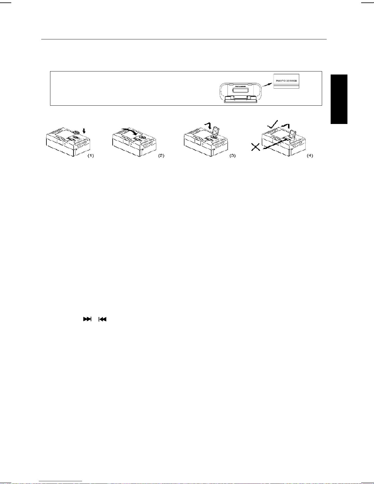
IMPORTANT! The identifiation No. is engraved
at the bottom of the inserts. Please refer to the
illustration above for the location of the No.
INSTALL THE iPod INSERT FOR DOCKING
1. Open the dock cover gently.
2. Gently press the correct insert into the dock. (Refer to the drawing 1 & 2.)
3. Place the iPod into the dock via the correct insert. (Refer to drawing 3.)
4. Never pull iPod forwards or push backwards. This can damage your iPod and/ or the main
unit. (Refer to drawing 4.)
CHARGING THE iPod
• While the iPod is docked and system is properly connected to AC power, it is charged
automatically until it is fully charged.
LISTEN TO THE iPod
1. Gently press the correct insert into the dock.
2. Place the iPod into dock via the correct insert.
3. Press the function button to select iPod mode, “iPod” icon will appear on the display.
4. Press PLAY/PAUSE button of the system to play the music from iPod.
5. Press PLAY/PAUSE button again to pause play, press again to resume play.
6. Press the VOLUME +/- button to adjust the sound level.
7. Press SKIP / button to skip forwards or backwards track, or hold the button to fast
forwards or backwards.
ENGLISH
LISTENING TO A NON DOCKING iPod OR OTHER PORTABLE AUDIO DEVICES
If you are using an iPod without a docking port or other MP3 player or other portable audio
device you can still play it through the unit via the AUX IN Jack.
1. Plug one end of the audio patch cord into the headphone or AUX OUT Jack on your device
and the other end of the patch cord into the unit AUX IN Jack located on the back of the unit.
2. Press the FUNCTION button on the unit or AUX button on the remote control. The
AUX icon will appear indicating AUX playing mode.
3. Turn on and play your device.
4. Press the VOLUME +/- button on the unit or MASTER VOL +/- button on the remote control to
adjust the system volume. You may need to adjust your device volume, too.
5. To turn off the unit, press the STANDBY/ON button (or button on the remote control). Please
remember to turn off your device, too.
E 16

CD OR CD+G OPERATIONS
PREPARATION
• This unit is designed to play CDs/CD+Gs bearing the identification logo “ / ”. If CDs/
CD+Gs do not conform to the CD standard, they may not play properly.
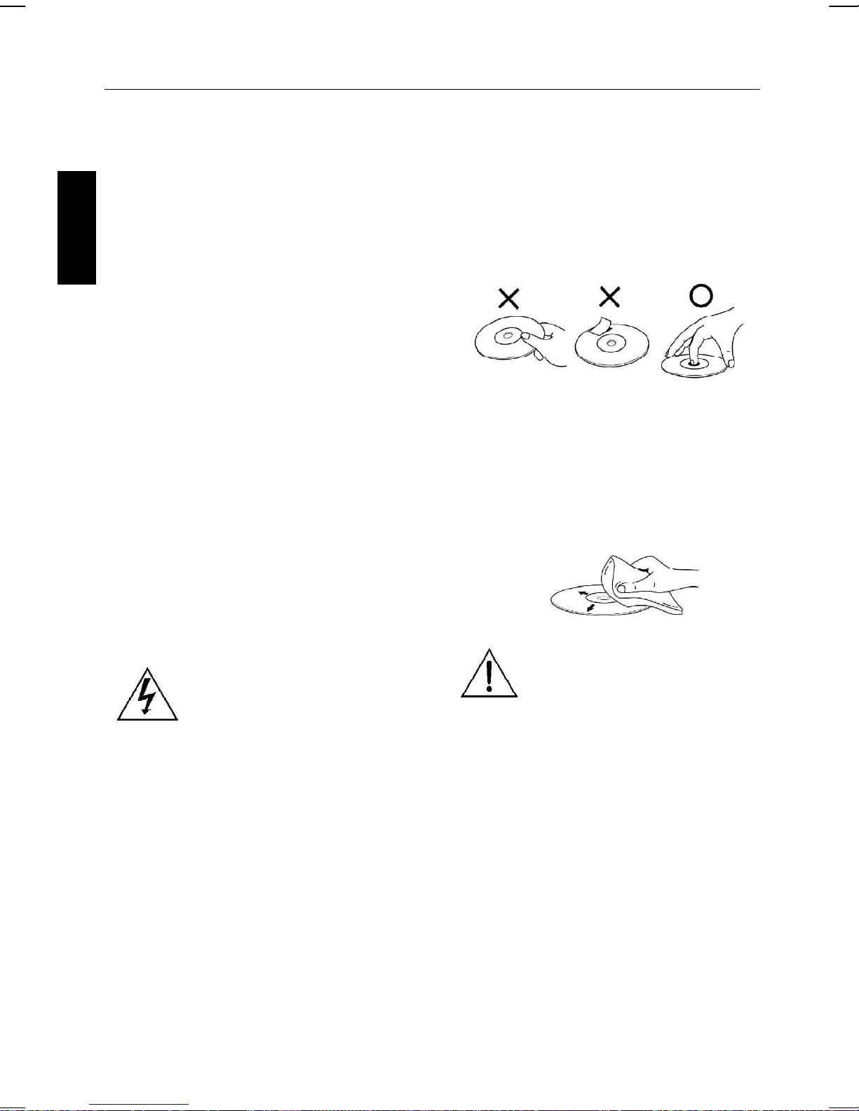
• Fingerprints and dust should be carefully wiped off with a soft cloth. Wipe in a straight motion
from the center of the disc to the outside edge.
• Never use chemicals, such as record cleaning sprays, antistatic sprays or fluids, benzene or
thinner to clean compact discs. These chemicals will permanently damage the plastic surface
of the disc.
ENGLISH
• Always place the compact disc on the disc tray with the label facing upward. Compact discs
can be played on only one side.
• To remove a disc from its storage case, press down on the center of the case and lift the
disc out, holding it carefully by the edges.
• Discs should be returned to their cases after use to protect them from dust and scratches.
• To prevent warping the disc, do not expose it to direct sunlight, high humidity or high
temperatures for extended periods of time.
• Do not apply paper or write anything on either side of the disc. The inks used in some felt-tips
pens may damage the surfaces of the disc.
PLAYING CD OR CD+G DISC
• Press FUNCTION button on the unit or CD/CDG button on the remote to select CD/CDG mode.
• Adjust MASTER VOLUME control on your unit, TV or audio system to a comfortable level.
• Adjust MIC VOLUME/A.V.C./ECHO/KEY controls as needed to achieve the desired mix of
music and vocals through your sound system.
• Do not press the disc cover of the CD compartment while it’s playing.
• Never place anything except a compact disc on the disc tray. Foreign objects can damage the
unit.
• Do not apply excessive force to disc cover.
• Only place one disc on the disc tray at a time.
LOADING A DISC
• Lift up CD door to open CD/CDG compartment door. Place a disc in the compartment
with the printed side facing toward you.
• Gently close the CD door to the CD/CDG compartment. After a few seconds, The unit begins
to read the disc. After that, the disc is playing automatically. (If no disc is loaded, it will display
“ “).
(Refer to the Trouble Shooting Guide on page E22 if a disc is loaded but it does not
work normally.)
E 17
CD OR CD+G OPERATIONS
PLAY/PAUSE MODE:
• To start playing, press the PLAY/PAUSE button. The PLAY “ ” icon will be displayed on the
LCD display.
• To temporarily stop playing, press the PLAY/PAUSE button. The PAUSE “II” icon will be
displayed instead of the PLAY icon.
• To resume play, press this button again.
PLEASE NOTE: Pressing pause when a CDG is playing may cause distorted lyrics on the
monitor. Any distortion will remain until the whole screen is refreshed during an instrumental
break or you stop the song and start it from the beginning.
STOP MODE
If the STOP button is pressed in the course of playing, the disc will cease to play. (The total
number of tracks will be shown on the LCD display.)
SKIP (FOR BOTH CD AND CDG DISCS)
• During STOP mode, you can skip up or down to your desired track or file by pressing a SKIP
button ( - SKIP - ).
• To resume playing the selected song, press PLAY/PAUSE button.
ENGLISH
SEARCH (FOR AUDIO CD DISC ONLY)
When playing any audio CD, press and hold the SKIP button ( -SKIP- ). The CD will
search at high speed in the forward or backward direction. Normal play will continue when you
release this button or press the PLAY button.
REPEAT
• To repeat the track currently playing, press the REPEAT button once. The “ 1” icon will be
displayed on the LCD.
• To repeat all tracks, press the REPEAT button twice. The “ ALL” icon will be displayed
instead of “ 1”.
• To clear the REPEAT function, press the REPEAT button again. The REPEAT icon on LCD will
turn off.
PROGRAM
• Use this button to program and play back songs in a preselected order.
Step 1: Programming should be done in the stop mode only. Press the PROGRAM
button and the icon will be displayed on LCD, the track will read [ ].
Step 2: Press the double arrow keys ( -SKIP- ) to select a desired track.
Step 3: Press PROGRAM button to confirm entry. You can repeat the same steps up
to a maximum of 16 tracks.
Step 4: Press PLAY button when you have completed programming and you are
ready to start singing.
• Press STOP button once to stop play.
• Press STOP button twice to clear all the programmed entries.
RANDOM
• Press RANDOM button to play tracks in random order.
E 18

OTHER OPERATIONS
KARAOKE FUNCTION
• The Echo and Key effects can function by pressing the ECHO/KEY button to switch and the
ECHO/KEY +/- buttons to tune their levels. Individual icon will be displayed on LCD for their
ON/OFF status.
• The Auto Volume Control (A.V.C.) can be switched ON/OFF by pressing A.V.C. button. AVC
icon will be displayed on the LCD to show its status.
ENGLISH
NOTE: KEY & A.V.C. functions only available on CDG mode.
* Warning - Tapping or dropping the microphone while it is on can permanently
damage your microphone. Resist the urge to swing the microphone around by the
cord!
E 19

RADIO TUNER OPERATION
Listening to Radio
1. Press function button, or RADIO/BAND button on the remote control to select radio mode.
2. Press BAND AM/FM button, or RADIO/BAND button on the remote control to select FM or AM
band.
3. Press TUNING +/- to select a radio station.
Note:
• Short press TUNING + or TUNING -, the receiving frequency step moves up or down
incrementally.
• If you press and hold TUNING + or TUNING - for more than few seconds, the frequency
will continue to increase or decrease automatically until a radio station is received.
• The last tuned station is retained and recalled when you turn the system on. The tuned
station is stored into memory even if power is disconnected or cut due to temporary power
failure.
Setting Radio Stations into Memory
You may store up to 20 FM stations and 20 AM stations in channel memory.
1. Press BAND AM/FM button to select FM or AM band.
2. Press TUNING + or TUNING - to select a radio station.
3. Press PROGRAM button to enter saving mode.
4. Press PRESET +/- button to select preset channel.
5. Press PROGRAM button to save into memory. If it has been previously set, the
former station is replaced.
6. Repeat step 2 to 5 to store additional stations.
ENGLISH
Playing Preset Stations
1. Press BAND AM/FM button to select FM or AM band.
2. Press PRESET +/- to select the desired preset channel.
Improving Reception
AM Reception
• Plug in the external AM antenna loop at the back of unit. (#23 note on. the control locations on
page E5.)
• The AM loop antenna should be placed up to 12” away from the unit for best reception.
Rotate the AM loop antenna as required for best AM reception.
• Do not put the other electronic adapter close to the system or antenna, this may increase
noise and influence the AM broadcasting station.
FM Reception
• Fully unwind the FM wire antenna and position it for best FM signal reception.
E 20
CARE AND MAINTENANCE
TURNING OFF THE UNIT
After using the unit, turn off the unit by
pressing the STANDBY/ON to OFF mode.
CLEANING THE UNIT
To clean the exterior of the unit, simply wipe
with a soft clean cloth moistened with plain
lukewarm water.
ENGLISH
ABOUT THE CD-Rs
This unit is compatible with CD-Rs but playback
capability may vary depending on the quality of
the disc, the recording device and application
software.
CLEANING THE CD LASER LENS
For the Best Results: Use a CD-lens cleaning
disc according to the cleaning disc
manufacturer instructions.
If a lens cleaning disc is not available, use a
clean, soft, dry cotton cloth to gently wipe the
small, glass, fish-eye laser lens located in the
CD players.
COMPACT DISC
HANDLING DISC
Although the music tracks in the disc are
covered with a protective layer, it is still
advisable to treat the disc carefully.
Ensure that you always pick up discs by the
edge, and put them back in their holders
immediately after use.
CLEANING DISC
Cleaning will not normally be necessary.
However, should fingerprints, dust or dirt
appear, you can wipe them off with a soft,
lint-free cloth. Wipe the disc in a straight line
from center to edge. You can moisten the disc
first with ordinary tap water if necessary.
To prevent fire or shock
hazard, disconnect your
stereo system from the
AC power plug when
cleaning.
NOTE: Do not use detergent
or abrasive cleaning agents,
as they can damage the
disc.
CD PLAYER
The player mechanism is fitted with
selflubricating bearings and must not be
oiled or greased.
E 21
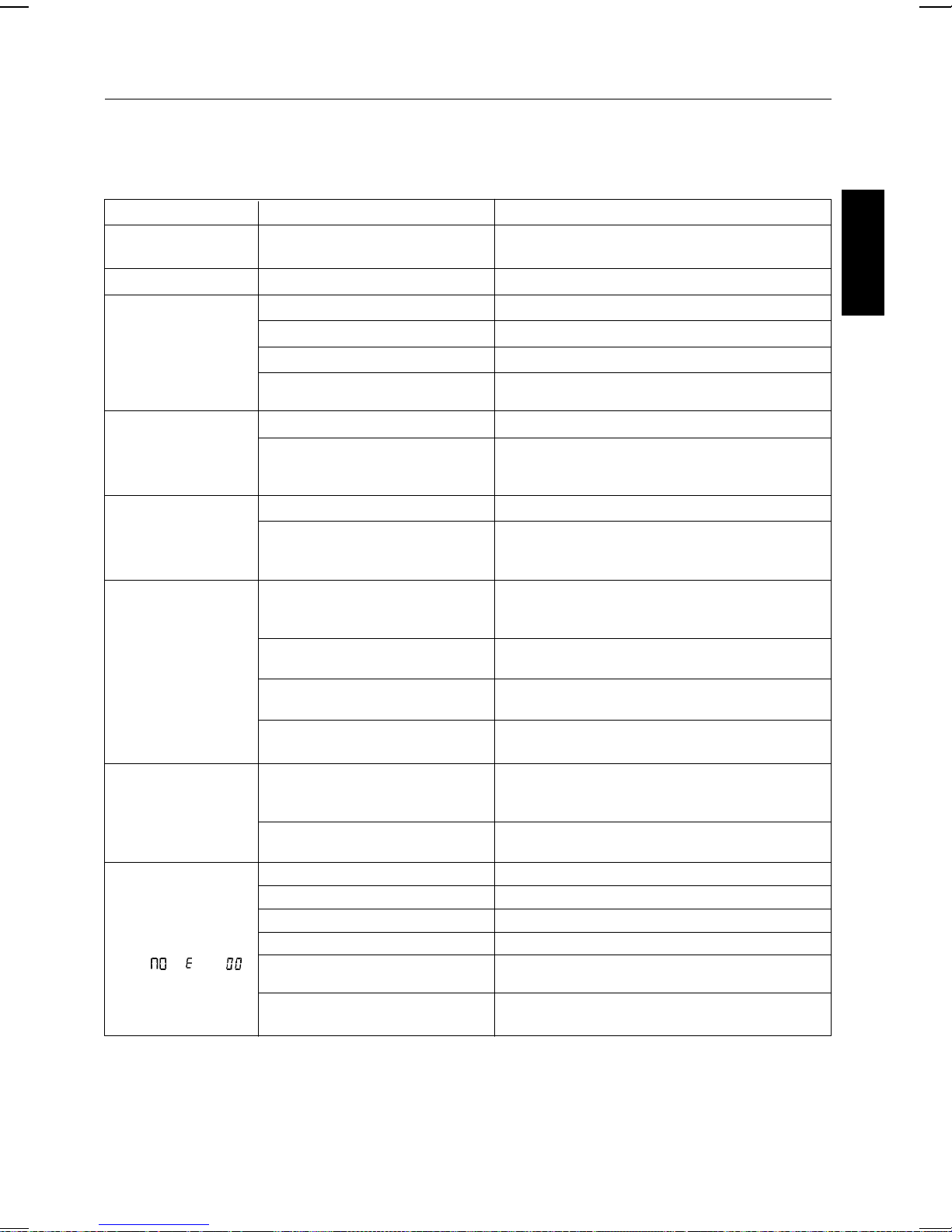
TROUBLE SHOOTING GUIDE
If you have followed the instructions and are having difficulty operating the unit, locate the
PROBLEM in the left column below. Check the corresponding POSSIBLE CAUSE column to
locate and remedy the problem.
PROBLEM POSSIBLE CAUSE SOLUTION
No power when the unit
is on.
No power when plugged in.
No sound from TV or PA.
Sound is distorted.
iPod does not dock
properly.
iPod does not respond to
the unit.
iPod did not charge up.
CD Player does not work
normally or the LCD displays “ “, “ “, or “ “
No power plug connection at the AC outlet.
The AC outlet may not have power. Check the outlet with a working lamp or other electrical appliance.
The wrong function is selected. Select the correct function.
TV or PA system is set to minimum. Turn up the volume on the TV or PA system.
TV or PA system is powered off. Power the TV or PA system on.
Patch cords are not connected securely.
Volume level is set too high. Decrease the volume.
Sound source is distorted.
Using no or wrong iPod Insert.
iPod did not install properly.
iPod is not installed properly.
Your iPod software is too old.
iPod is locked up.
Using first or second generation
iPod, iPod Shuffle or other devices.
iPod is not installed properly.
iPod is locked up/frozen.
Disc is inserted upside down. Insert disc correctly.
Disc is dirty. Wipe clean with soft cloth.
Disc is scratched. Use a new disc.
Disc is warped.
A nonstandard disc is inserted.
The unit needs to be reset.
Insert the power plug into the AC outlet.
Ensure white and red patch cords are securely inserted into
both the karaoke system and the TV/PA system.
If the iPod original sound source (MP3) is of poor quality,
distortion and noise are easily noticed with high-power
speakers. Try a different audio source such as a music CD.
Make sure the dock insert is the proper fit for your iPod.
Remove your iPod from the dock and check for obstruction on
the connectors in the dock and on your iPod. Then reseat it in
the dock.
Remove your iPod from the dock and check for obstruction on
the connectors in the dock and on your iPod. Then reseat it in
the dock.
Upgrade software on your iPod. For details visit http://www.
apple.com/iPod/download.
Please make sure your iPod is working properly before docking into the unit. Please refer to your iPod manual for details.
This unit cannot support those iPods or other devices. Use
AUX as their input channel.
Remove your iPod from the dock and check for obstruction on
the connectors in the dock and on your iPod. Then reseat it in
the dock.
Please make sure your iPod is working properly before docking into the unit. Please refer to your iPod manual for details.
Use a new disc.
Only use discs bearing standard logo as described on page
E17.
Disconnect the machine from the power source for 30 sec-
onds the reconnect.
ENGLISH
E 22
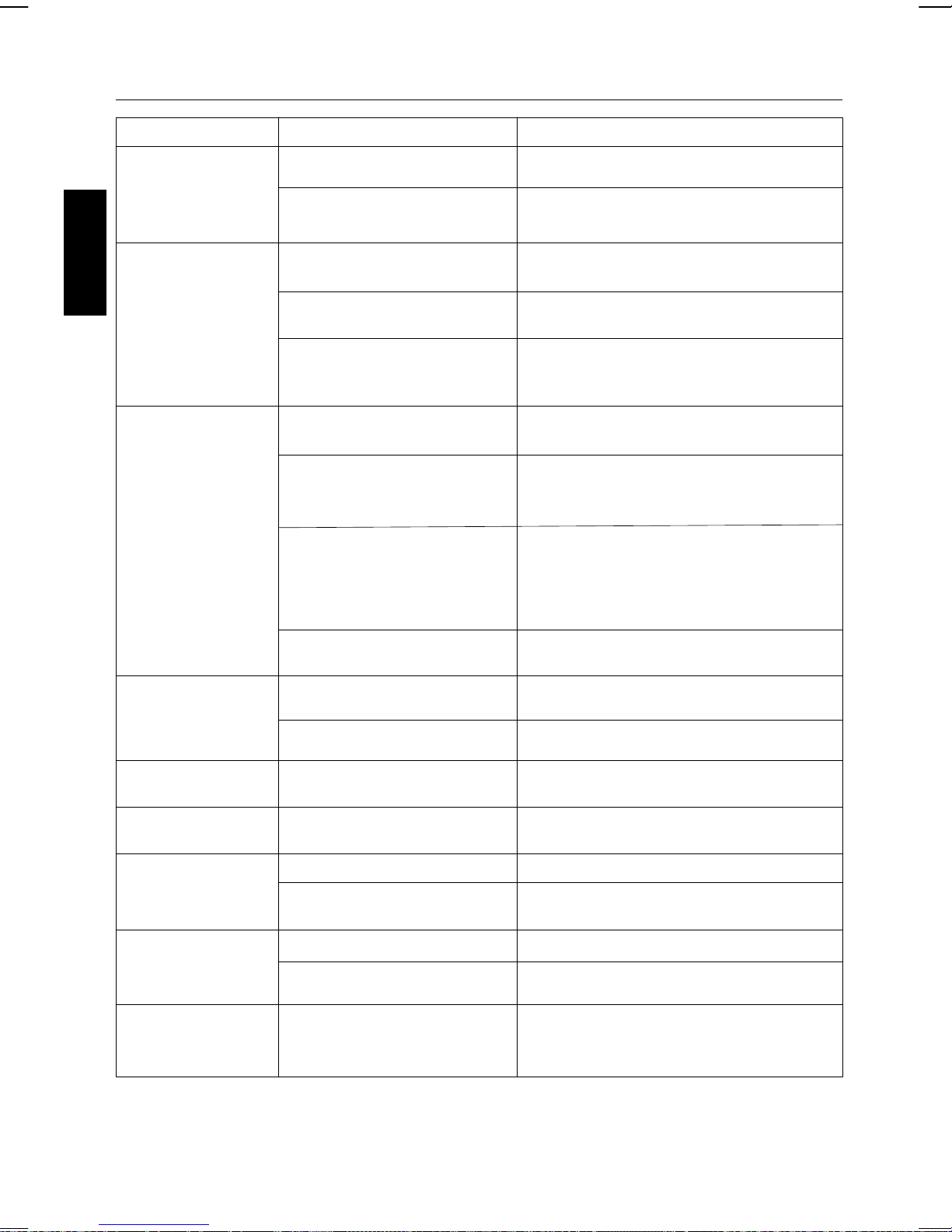
TROUBLE SHOOTING GUIDE
PROBLEM POSSIBLE CAUSE SOLUTION
No sound - If audio is going through TV or VCR.
Source Selection on TV or VCR is not
correct.
Patch cords are not connected
securely.
Follow directions on page E11 for “Making the Connections”
Ensure white and red patch cords are securely inserted into
both the karaoke system and the home stereo system.
No sound - when audio is
ENGLISH
connected to a home
stereo.
No song lyrics appear
on the TV screen.
While playing a CDG and
singing with the
microphone, the music or
vocals cuts out.
Source Selection on your stereo is not set
properly.
Improper Connection to stereo system
or PA.
Patch cords are not connected securely.
Video cable is not connected properly to
the TV.
Source selector on TV is not set to
VIDEO.
TV does not have video line input.
A CDG is loaded but the “CDG” icon is
not lit.
Sound channels are not adjust properly.
Playing music only track. Play track that includes music and vocal.
Select AUX IN as the source for your home stereo.
Follow direction on page E12 for connection to a home
stereo system.
Ensure white and red patch cords are securely inserted
into both the karaoke system and the home stereo system.
Connect the video cable to the karaoke system VIDEO
OUT and to the TV VIDEO IN.
Using your TV remote to select VIDEO input or select the
proper VIDEO input on the TV itself. (Refer to page E11
under Common ways to configure your TV or VCR).
Connect from VIDEO OUT of the system to the VIDEO IN
on your VCR or connect to an RF Modulator and then to the
TV cable input. Refer to “Making the Connections” on page
E11. Check the disc to be sure it is a CDG. (See page E25
for details.)
Check disc to be sure it is clean. (See page E21 for cleaning instructions.)
Press AVC button to turn off the function.
No AM band radio sound but
others OK.
AM band radio is very noisy.
Battery Low icon always on.
Remote Control did not work.
Unit gets warm after
extended play at high
volume.
AM loop antenna is not connected to the
unit.
AM loop antenna is not located properly.
Batteries are weak.
Batteries were not installed properly.
Battery weak.
Remote Control is not pointed toward to
the main unit.
This is normal.
Plug the AM loop antenna connector to the jack on the
back of the unit.
Move the AM loop antenna away from the main unit and
rotate it for best reception.
Replace with new batteries.
Check to make sure the polarity (+ & - ends) matches the
diagram in the battery compartment.
Replace current battery with new battery.
Point the Remote Control toward the main unit, move within
10 feet of the unit.
Turn unit off for awhile or lower the master volume.
E 23
 Loading...