

Page 1
TR-700NW/AW Configuration Guide
Before You Start
Ver. 1.01
Take a few moments before you start to make the following simple checks. A few moments spent before you start installing your
system can save a lot of time later by avoiding some of the most common problems that users can encounter.
I) Administrator Rights
For installation of TandD software and drivers it is ABSOLUTELY NECESSARY that you have complete administrator rights.
Go to Control Panel > User Accounts and confirm that this is the case. If it is not, then stop right here and correct it.
II) Firewall Settings
The TR-700NW/AW resides on your network independently from any PC, with its own IP address. In order for it to perform its
functions, however, the unit will have to have an unimpeded communication path to the FTP and Email servers that you specify in the
settings. This may also include unimpeded ACCESS TO THE INTERNET. Your network may have firewalls which block this
access so it will be necessary to attend to this early on in the setup process.
III) SPAM Filter Settings
If you are going to be sending warning monitoring emails be sure to set your
SPAM filter not to block them.
IV) Other Help Sources
Note that TR-700W for Windows has both a Help file and an Operational
Guide that contain tips for setup and troubleshooting suggestions. As unusual
as it may seem, TandD’s Help Files actually are helpful. You can find a lot
of useful information in them, so try looking there if you are having
problems.
Page 2
Starting the TR-700W Settings Utility
I) Getting Started
1. After installing TR-700W for Windows on your PC go to the Start Menu and launch the TR-700W Settings Utility. If you
have questions about installing the software or the USB Driver open TR-700W for Windows and then select Help for Unit
Recognition Failure. The Guide has very complete instructions for this.
2. Next connect the TR-700NW/AW to your PC using the USB cable supplied with the unit. (Hint: The USB port is on the
bottom of the logger.) If the USB driver installed correctly the software should automatically discover the 700W. You will
see a “USB Communication in Progress” notification and the device will appear in the Utility Main Window. If this doesn’t
happen automatically you may have to manually associate the USB Driver with the 700W in your PC’s Device Manager.
Page 3
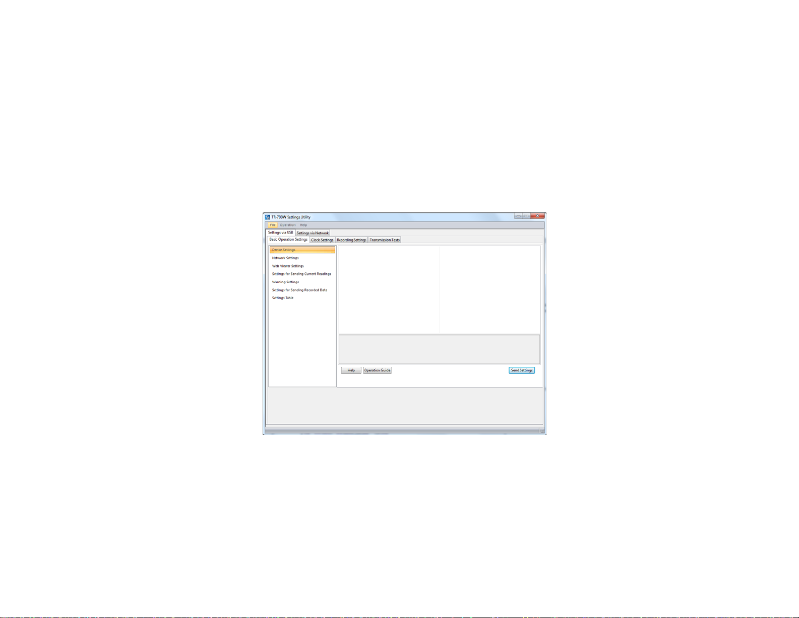
3. The TR-700W Settings Utility will open to the Settings via USB and Basic Operations tabs with the Device Settings page
selected. The software will automatically populate the Device Settings Page from the unit that is connected.
Page 4
The TR-700W Settings Window
II) The Settings Process
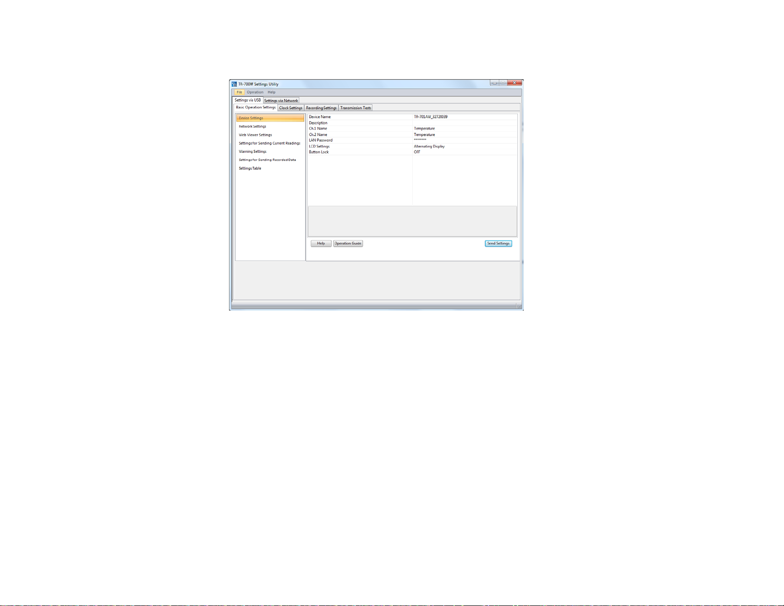
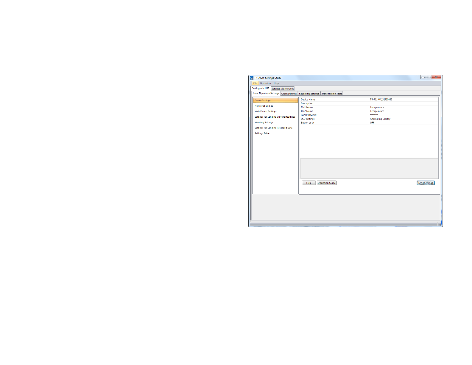
Making settings to control the operation of the TR-700NW/AW is
a remarkably straightforward process that is all accomplished
through the Settings Window, shown here. Initially the device
must be set up via USB in order to establish the Network Settings.
Once this is done the device can be reconfigured over a network.
The window is divided vertically in two, with page selections in
the left hand pane and page contents on the right. Settings are
made by selecting a settings page from the pane on the left and
then filling in the entries in the page on the right. The process
starts with the top page (Device Settings) and then moving down
the page list, making the settings page by page, until the last page
(Settings for Sending Recorded Data) has been completed. (We
will talk about the Settings Table later.)
AFTER MAKING SETTINGS BE SURE TO CLICK ON
“SEND SETTINGS” BEFORE LEAVING EACH SCREEN
III) Basic Operation Settings
1. Device Settings
There is not much to discuss here. The Device Name and Description fields can be used to enter a logical name for the TR-700W that
may have more meaning to you than the factory assigned serial number. This can be particularly helpful if you have more than one
700W on your network. You can also customize the Channel Names, select the mode of the LCD display and whether to lock out the
unit’s front panel buttons. The LAN Password will be used to access the 700W later when it is connected to your network, rather than
via USB.
Page 5
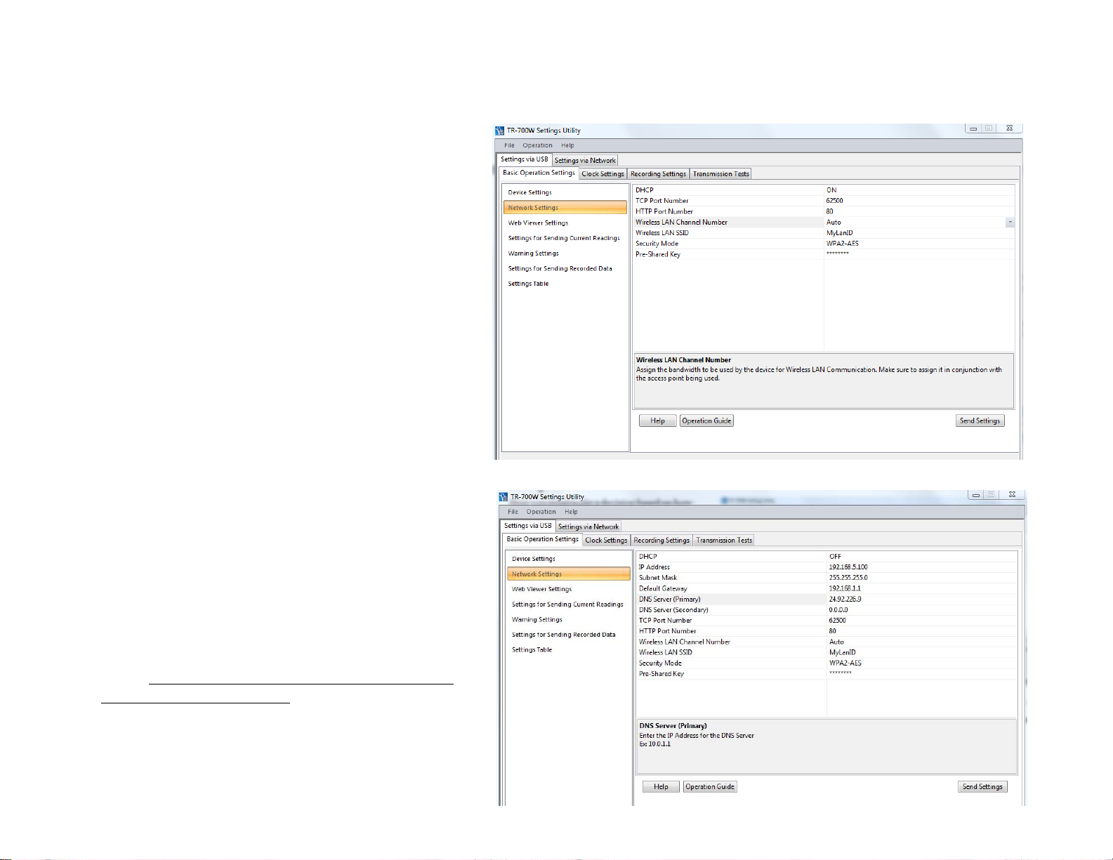
2. Network Settings
Here you must make a decision based on how you
intend to use the unit. If you are not going to access
the device’s built-in Web Server, then set the DHCP
field to ON and the settings boxes for IP address, etc.
will disappear and can be ignored. If you are going
to use the internal Web Server, however, this
requires a fixed IP address. In this case set DHCP to
off and make the entries for the IP Address you will
use along with the Subnet Mask, Default Gateway,
and DNS Server(s). If you are unsure what to enter
for these values see Appendix I; Determining Router
& Server IP Addresses
Note that when you select an entry in the right hand
window you will also see some basic guidance for it
along the bottom.
If you have a TR-700AW you will also need to make
the settings for your wireless LAN. If you are in
doubt about what settings to use here check the
documentation that came with your router, or with
your IT department. Remember that the SSID and
password are case sensitive. As a note, the TR700AW supports WPA2 encryption for use in
802.11n networks.
Note: At this time the TR-700AW does not support
Enterprise Mode encryption.
Page 6

3. Web Viewer Settings
This is a very simple window. You can select the
update interval for the Web Viewer and a title for the
window that will show in the Browser.
4. Settings for Sending Current Readings
In this window you can elect to send Current Readings
from the unit, how often they are sent and by what
means. Here we are sending the readings every 5
minutes via FTP to TandD’s free WebStorage Service,
although you can select any FTP server. You can also
elect to send Current Readings by E-Mail, although this
may result in a lot of E-Mails. Note that if you are
sending Current Readings to TandD’s free WebStorage
Service via FTP, the Destination Folder must be left
blank.
If you want to keep your data within the confines of
your own network, and you don’t have access to an
existing in-house FTP server, there are alternatives.
Most routers today have an FTP function to an attached
USB drive. Also there is free software available from
companies like Filezilla or zFTPServer that can turn
any PC into an FTP server (it will need a fixed IP
address however).
Page 7

5. Warning Settings
This is the window where warning notifications can be
enabled for readings that exceed preset limits. You can
elect to enable the contact pair for triggering an external
device only or to also send a Warning Notification
Warnings are sent via E-Mail or can be a Text to Cell
Phone using the carrier’s E-Mail to SMS Gateway.
Here you see one warning E-Mail being sent and text
messages to an AT&T and a Verizon cell phone. You
can designate up to 4 recipients.
If not already done, here is where to make the settings
for the server you will be using to send Warning
Emails, should you choose to do so. You will need to
determine the type of authentication, if any, required by
your Email server. The TR-700W supports either
SMTP Authentication or POP Before SMTP. For
SMTP Authentication the TR-700W uses the LOGIN protocol. If you are unsure about this you should check with your Service
Provider, your IT Specialist, or you can try using the “ehlo” command as described in Appendix II at the end of this guide. If you are
using an in-house server, or have a direct connection to your Email server, it is possible that it may not require any authentication at
all.
A Note About Free E-Mail Service: Some of the most popular free e-mail services, such as Gmail and Hotmail, use SSL
encryption, which the TR-700W does not support. Because of this, these services cannot be used to send warning or data E-Mails.
There is, however, a free POP3 E-Mail service provided by GMX which has been tested to work with the TR-700W. An account for
free POP3 Email service can be quickly established at www.gmx.com. When setting up the TR-700W for a GMX account use the
settings shown above:
Page 8

A Note about Microsoft Exchange Server: The TR-700W will work with MS Exchange Servers. In order to do so, however, it will
be necessary to have the IT Specialist who maintains your server set up an unencrypted Client to Server Connector for the TR-700W
on port 587
If you have elected to enable Warnings you will want to
set the limits which trigger them. You can set upper
limit or a lower limit, or both for either channel or both
channels.
Note that due to the internal workings of the logger the
temperature limits for Warnings must be stated in
Degrees Celcius.
You are also asked to enter a Warning Judgment Time.
This is not the warning sampling Interval. This time is
the duration that the set limit must be exceeded before a
warning notification will be sent. The unit will send a
Warning Notification to all designated recipients when
this condition is met. It will only send the warning once,
but will send an OK Notification when the readings
return to within normal limits.
The last entry on this page enables the unit to send a Warning Notification when the unit detects that a sensor has been removed or has
become defective. You can enable this for either channel or for both.
Page 9

6. Settings for Sending Recorded Data
This is the screen where downloads of the data recorded
by the loggers are enabled, the frequency of downloads is
specified and the transmission method is set. Recorded
Data can be sent at either a fixed time and day, or at fixed
intervals. The selected transmission method applies to all
times specified. Note that if transmission via FTP is
selected and <time> is not included in the File Name,
each transmission will overwrite the previous one,
resulting in a single data file residing on the server no
matter how many uploads are made. Also, as with
sending Current Readings, it is important to make sure
that if Recorded Data is being sent to TandD’s free
WebStorage Service the Destination Folder entry must be
left blank.
7. Settings Table
The Settings Table is a convenient way of viewing all the
settings you have made in summary form. This can be
handy for troubleshooting problems or just confirming
that settings have been made as intended. Your
distributor’s technical support specialist may ask you to
send screenshots of the Settings Table to assist in a
troubleshooting procedure. It is recommended to take a
screen capture of this table for future reference.
Page 10

8. Clock Settings
There’s not a lot to say about this screen that isn’t already
self-evident, with the possible exception of a comment
about the necessity for an SNTP server connection. In
addition to correcting any errors to the TR-700NW/AW’s
internal time keeping, a connection to an SNTP server also
allows for automatic clock setting after a power failure or
surge. While the logger readings would be unaffected,
without this all 700W originated messages for warnings
and the like will show erroneous times until the unit is
manually reset by the user. Again, be sure that any
firewalls in your network allow connection to the time
server.
9. Recording Settings
It is in this window that you set the basic logging
parameters for the device. Mostly this is all selfexplanatory.
One important point is that it is in this window where you
can enter any Adjustment Settings. This allows you to
enter any reading errors that are noted during a calibration
process. Once this is done the data that is displayed and
recorded by the unit is “post correction”, and further
adjustment after downloading becomes unnecessary.
Note that adjustments are linear and can be either “1 Point”
(offset) or “2 Point” (mX + b). The TR-700W cannot
accept quadratic corrections (aX2+bX+c).
Page 11

10. Transmission Tests
You will want to perform these tests prior to deploying the
unit for service. Doing so now can save a lot of
troubleshooting time later.
Important Note: The Transmission Tests determine if
communication can be established via the specified method
without errors being returned. Because of this the TR700NW/AW must be connected to the network. This may
seem obvious after thinking about it, but it is surprising how
often people just proceed to this step while still only
connected via USB.
Disconnect the USB cable and plug in the power cable from
the A/C Adapter.
If you are configuring a TR-700AW the unit will attempt to
connect to your wireless LAN. The Link LED (located on
the right side of the unit) will blink while a connection is
being established. If the connection is successful the Link
LED will remain on solid. If the Link LED goes off the connection to the Wi-Fi router could not be established. If this is the case you
should recheck the SSID, however the most common cause is the Security Mode or Shared Key. Double check these settings against
those of your router. Please recall that the TR-700AW units do not support Enterprise Mode security.
If you are configuring a TR-700NW connect the unit to your LAN with an Ethernet cable. TR-700NW devices will always connect
unless there is a problem with the cable or the router is not configured for DHCP and the logger is expecting to receive an IP address
from it.
Next, click on the Settings via Network tab. The software should show a Searching notice and then show your logger in the Address
List window. Double click on your logger in the Address List and you will be prompted to enter the LAN Password you set in the
Device Settings page. At this point, as long as the password you entered is the correct one, and you have no firewall issues, the
software will connect with the logger through the network.
Page 12

You can now perform the Transmission Tests. Note that while the test is in progress you will usually see a status in the Result
window. If the test completes without error you will see a Successful result. If not, a Failure will be reported along with some
information about the cause. This usually requires changes to the settings that were made earlier.
NOTE: Most E-Mail failures are the result of authentication issues. If you receive a Failure result for an attempted E-Mail see the
comments relating to this in Section 5: Warning Settings.
Once all of the Transmission Tests for the operations you have enabled have been completed you can close the TR-700W for
Windows software and the logger is ready to deploy.
Page 13

Determining Router & Server IP Addresses
Key addresses for your router and ISP server can be
obtained from your computer. In order to display this
information use the following procedure:
1. Connect your PC to the LAN that the TR-700W will
reside on.
2. Go to the Start menu and click on Run.
3. Enter “Cmd”.
4. In the DOS prompt window enter “ipconfig/all”.
5. In the “Connection” Section find:
- The IP address of the PC
(as assigned by the router)
- The assigned subnet mask
- The router’s default gateway address
- The IP address of your ISP’s DNS server
Appendix I
DOS Prompt Window
Page 14

Appendix II
Determining E-Mail Authentication Type
This procedure can be used with many E-Mail servers to determine what authentication will be accepted.
1) Open the Cmd prompt. Then type:
telnet <server_name>
<smtp_port_no> (return)
2) After server response, Type:
ehlo <your_domian_name> (return)
3) The server will respond something like the following:
In this case you can see that Earthlink
accepts PLAIN, LOGIN and CRAMMD5 smtp authentication. Since
LOGIN is accepted the TR-700W will
work fine with this server.
1762 W. 20 S. #100, Lindon, UT 84042
Ph: 801-756-7705 Fax: 801-756-8948
www.thermoworks.com
 Loading...