

Page 1

RTR-500GSM Configuration Guide
First Things First
Ver. 1.11
I) A Note About User Documentation
In order to avoid a thick and complicated manual, most of the user documentation for the RTR-500GSM is based in two Help files,
both of which are found in the Help pull down menu. As strange as this may sound, TandD’s Help Files really are helpful. There is a
lot of information on the use of the Settings Utility in the Help file, and if you don’t find the answer to your question there try the
Operation Guide.
II) About SIM Cards & Accounts
In order to use the RTR-500 GSM you will need to have a SIM card from a GSM Service Provider. In the US this would be either
AT&T or T-Mobile. There are several GSM providers in Canada, most notably Rogers. The RTR-500GSM can use any standard
voice account SIM that supports GPRS Data (Web and Email) and has funds applied for Data; THIS IS A MUST. The account can
be either pre-paid or post-paid, and can be purchased at retail outlets. Since the RTR-500GSM is a data only device, the number of
voice minutes or cost per voice minute of the account you choose are not important as no voice minutes will be used by the device.
III) Install the SIM card
Remove the battery cover from the RTR-500GSM and install the SIM card. If you have questions about how to do this refer to the
Introductory Manual. It has detailed instructions starting on Page 19 for this that are quite complete. Don’t forget to install the
batteries after the SIM card is in place.
IV) Install the Software
Make sure that USB driver installs correctly. There are very complete instructions for this in the Introductory Manual starting on Page
25.
Page 2

Getting Started
I) Connect the RTR-500GSM to your PC
First make sure the Run / Stby switch is in the Stby position
and plug in the A/C adapter. Next plug the RTR-500GSM
into a USB port on your PC. The RTR-500GSM Settings
Utility should open automatically as shown here. If not, go
to your Start Menu and open the software.
II) Check the Following Points
A) Check the LED’s on the front of the RTR-500GSM unit. If the orange ERR LED is on steady there is a problem with the SIM
card. It is either installed incorrectly, invalid, locked or defective. You can go no further until this condition is corrected.
B) In the normal case you should see the green PWR LED turn on steady for a bit, blink for a few moments while the unit
communicates with the PC through the USB connection, and then remain on steady. The unit can take its power from the USB
port but not all functions will be enabled. Make sure you install the batteries or plug in an A/C adapter to continue, even
thought the unit seems to be working fine at this point.
C) After downloading for a few moments you should see the RTR-500GSM appear in the Settings Utility window, as shown
above. If this does not happen, the most likely cause is a problem with the USB driver which needs to be corrected before
proceeding. Again, there are very complete instructions for installing the USB driver in the Introductory Manual starting on
Page 25.
D) At this point, the first time a new RTR-500GSM is connected the Initial Settings Wizard should open. If it doesn’t you can
open it manually by clicking on View > Initial Settings Wizard from the pull down menu. For subsequent connections the main
settings window would open.
Page 3

Initial Settings Wizard
The Initial Settings Wizard allows you to quickly enter the basic information
needed to connect through the cellular system for which you have opened an
account.
I) Setting the APN
The APN (Access Point Name) tells the system which server to use for sending
data and SMS messages to and from the RTR-500GSM. This should be set to
“wap.cingular” for AT&T accounts or epc.tmobile.com for T-Mobile.
II) User ID and Password
Unless instructed otherwise when you obtain your account, this should be left
blank. The wap.cingular access point does not require User IDs or Passwords.
III) Test the Network Connection
When you click on the Next button you will be offered the opportunity to send
a test SMS message. This should be done, as it tests the unit’s basic
connection to the network. Just enter the phone number of an SMS capable
cell phone and click the Send button. If the test message does not arrive in
short order there is a fundamental problem with the unit’s network connection
which needs to be troubleshot before proceeding to the Main Settings Window.
(Note: A successful SMS test will verify your basic account and connection
with the carrier, but it does not confirm the data account. This is done with
the Transmission Tests described in Section 11.
Page 4
Test Message Failures
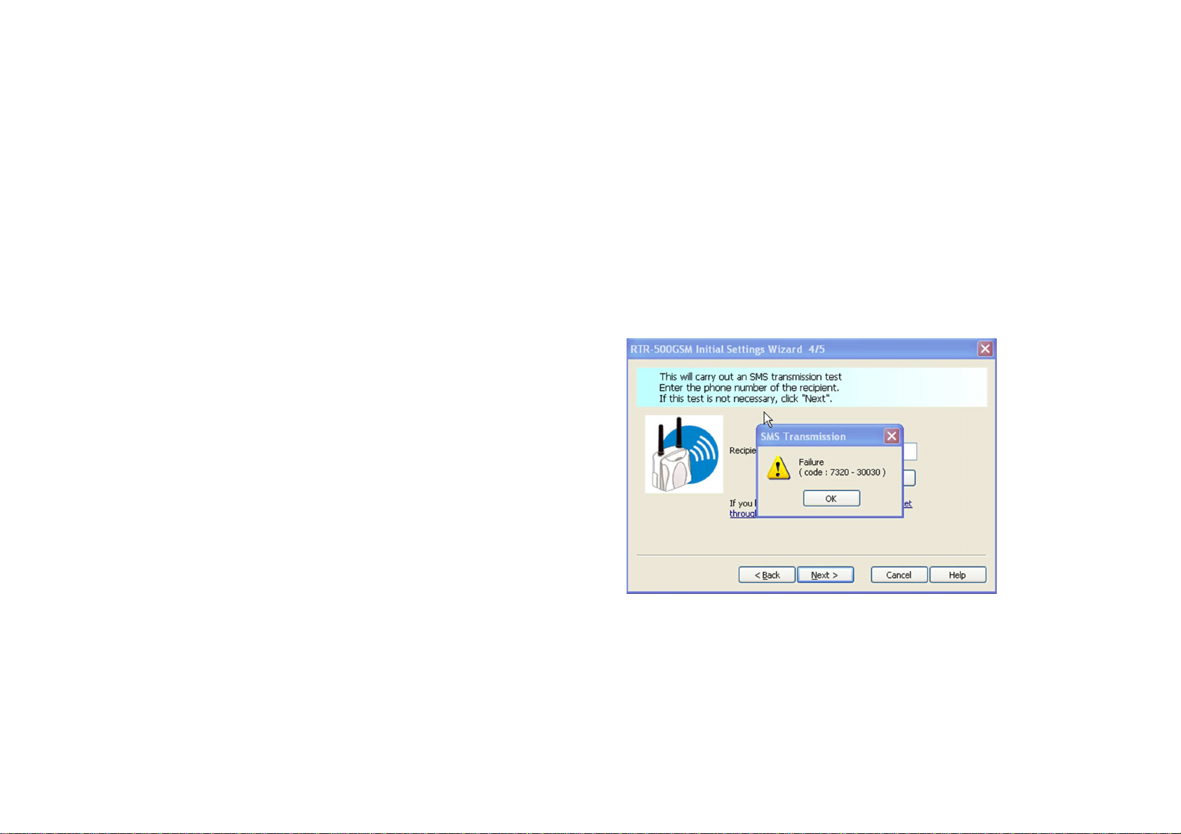
If your test SMS Transmission completed successfully you can skip this section. If it did not, however, you will most likely see a
Transmission Failure message like the one pictured here. There is a complete list of Error Codes in the Documents section of the
Operation Guide. Some of the more likely failure codes and their causes are as follows:
Note: Using the SIM card to send an SMS message from a cell phone does not confirm that the GPRS plan is active. To do
this you must be able to send an email from the phone.
1) Failure Code 7320 - 30030
No GSM connection or signal from the Cell Tower. Most
likely, the RTR-500GSM is either not in a Cell system service area
or is in a “dead zone”. Try relocating the unit near a window.
Radio reception can be poor in steel reinforced concrete buildings.
2) Failure Code 7320 -30013
Failure to locate APN: The APN entered in the Initial
Settings Wizard cannot be found. Double check the entry. It
should read “wap.cingular” for the AT&T system.
3) Failure Code 7326 - 30000
Failure to log onto APN or to find destination phone Check
that the User ID and Password for the APN are correct and that the
phone number you entered is a valid one.
4) Failure Code 7320-30007
Failure to recognize SIM card: The most likely cause for this
is a bad connection. Try reseating the SIM card in the holder.
Page 5

The RTR-500GSM Settings Window
I) The Settings Process
Making settings to control the operation of the RTR500GSM is a remarkably straightforward process that is
all accomplished through the Settings Window, shown
here. The window is divided vertically in two, with
page selections in the left hand pane and page contents
on the right. Settings are made by selecting a settings
page from the pane on the left and then filling in the
entries in the page on the right. The process starts with
the top page (Base Unit Settings) and then moving
down the page list, making the settings page by page,
until the last page has been completed.
AFTER MAKING SETTINGS BE SURE TO
CLICK ON “APPLY” BEFORE LEAVING EACH
SCREEN
1. Base Unit Settings
There is not much to discuss here. Enter the name for your base and the units of temperature measurement you want to use. Leave
Control by SMS Off to start with. It can be turned on later if you intend to use this feature. Not that the unit’s Log File can be
downloaded from this screen (Show Log button). This may be used by your distributor’s tech support specialist in helping you
troubleshoot system problems.
Page 6

2
Remote Unit Settings
The Remote Unit Settings screen is used to register Loggers to the
system. When a Logger is placed on the 500GSM you can set, via
optical communication, the Logger recording parameters, assign it to a
logical group and give it a logical name, set the RF communication
channel, enable warning monitoring and set the upper and lower
reading limits which trigger warnings. Every Logger that is to be
monitored or downloaded by the RTR-500GSM must be registered to it
using this screen.
One note about Warning Monitoring: When you set Warning
Monitoring to On for a logger you will have the option to enter a
Warning Judgment Time. This is not the warning sampling Interval, which is fixed at 10 minutes for the RTR-500GSM. This time
is the duration that the set limit must be exceeded before a warning notification will be sent.
3
Repeater Settings
If you intend to use wireless repeaters in your system to address
communication range issues you will use this screen to register them. If
not, you can skip this section (screen) entirely. The only tricky part
here is that in order to register a repeater to your system you will need
to plug an RTR-500 into a USB port on your PC with the Repeater
Setting screen selected. You can do this by plugging it into a 2nd USB
port on your PC, or by unplugging the 500GSM and using its USB
connection for the repeater. Once the RTR-500 is connected click the
“Register” button in the Repeater Setting screen. Make the appropriate
entries in the pop-up window and click on Register. The repeater will
now be listed in the Repeater Settings screen. When finished
disconnect the RTR-500 from the USB port and reconnect the 500GSM.
Page 7

4
Wireless Route Settings
In this screen we can see that this system has two Loggers and
one Repeater registered. Initially after registration the
software automatically assigns all devices to communicate
directly with the RTR-500GSM, as shown in the screen to the
right. This may be fine in some cases, but if you are using a
repeater it is probably not what you want. To change the
communication path for a device simply drag and drop it on
top of the device you want it to connect through. In the 2nd
screen to the right you can see that Unit 01 has been dragged
to communicate through the repeater. (Don’t forget to click
“apply” after changing a device’s communication route.) Even
if you have no repeaters in your system you will want to do the
next step below.
There is something else shown in this 2nd screen that is very
interesting and useful. That is the results of the Signal
Strength Test. Clicking on the Test Signal button will cause
the system to perform an RF signal strength test for all
registered communication paths and display the results. In this
case we can see that all routs are 5 / Green, which is as good as
it can get.
NOTE: This test can be very useful in troubleshooting
intermittent communication errors. When the RTR-500GSM
and Loggers are in place perform this test. If there are results
in the 1 or 2 category intermittent communication problems
are likely.
Page 8

5
Clock Settings
This is the screen where you set the RTR-500GSM’s internal
clock. You can set the current time to match your PC or to
another time, for example if you are planning to deploy the unit in
a different time zone. It is important to do this because with
firmware versions 1.03 and below, even if you turn “Set Clock to
Carrier” on, it will only adjust the minutes (for accuracy purposes)
but not the hour (for time zone purposes). This is corrected in
later firmware versions to take the entire time and date from the
carrier.
6
Email Settings
This screen is where you make the settings for the server you will
be using to send Emails for Warnings, Data Downloads or Current
Readings, should you choose to do so. You will need to
determine the type of authentication, if any, required by your
Email server. The RTR-500GSM supports either SMTP
Authentication or POP Before SMTP. For SMTP Authentication
the RTR-500GSM uses the LOGIN protocol. If you are unsure
about this you should check with your Service Provider, your IT
Specialist, or you can try using the “ehlo” command as described
in the appendix at the end of this guide.
Page 9

A Note About Free E-Mail Service: Some of the most popular free e-mail services, such as Gmail and Hotmail, use SSL encryption,
which the RTR-500W does not support. Because of this, these services cannot be used to send warning or data Emails. There is,
however, and excellent free POP3 Email service provided by GMX which has been tested to work with the RTR-500GSM. An
account for free POP3 Email service can be quickly established at www.gmx.com. When setting up the RTR-500GSM for a GMX
account use the settings shown above:
7
FTP Settings
This screen is where you make the settings for transferring data from
your loggers to an FTP server, should you choose to do so. If you do
not have access to a local FTP server, as a TandD customer you are
welcome to set up a free WebStorage Service account on TandD’s
server. Use this link: http://www.webstorage-service.com/services/
to learn more about TandD’s free WebStorage Service and to set up
your account. Typical settings for a WebStorage Service account are
show in the screen capture on the right.
8
Settings For Sending Current Readings
Now that the RTR-500GSM knows where to send data you will want
to tell it what data to send and how to do it. The first data type is
Current Readings from the loggers. If you want Current Readings to
be sent make sure to set the first line item to ON. Then select an
interval and a method of sending, for which there are 3 choices. The
first is to send via Email. If you select this you will have the option
Page 10

of having an XML file with the readings included as an attachment.
The next choice is to send via FTP. This will result in an XML file
with the Current Readings being uploaded to the specified FTP server
and the selected sending interval.
If you select FTP you should be aware that if you choose <base> for
the File Name each upload will overwrite the previous one, so that
there will be only one file created on the server. If you want to create
a sequential series of files you will need to select a File Name that
includes <time>. If you are uploading to a WebStorage account be
sure to leave the Recipient Folder entry blank.
9
Warning Report Settings
To enable warning reports to be sent when loggers go into an alarm
condition set Warning Monitoring to On. Warnings can be sent to up
to four recipients. These can be either Emails or SMS messages to
cell phones. To send a warning message as an SMS simply enter the
mobile phone number in the Recipient field. Note that warnings will
only be sent for loggers that have had Warning Monitoring set to On
during remote unit registration. When the alarm condition has ceased
to exist a Recovery message will be sent.
Note: The RTR-500GSM is triggered by transitions from normal to
alarm condition, and visa versa. When testing this function before
deploying it is important to understand that a warning will not be sent
if the logger is already in an alarm condition when the unit is first
placed into Run. In order for an alarm to be sent the logger must be
first in a normal condition and then move into alarm.
Page 11

10
Send Recorded Data Settings
This is the screen where downloads of the data recorded by the loggers are
enabled, the frequency of downloads is specified and the transmission
method is set. Recorded Data is delivered as a .trz file, which is viewable
using TandD’s Graph software, and can be sent as frequently as eight
times per day. Note that the selected transmission method applies to all
times specified. Again, if transmission via FTP is selected and <time> is
not included in the File Name, each transmission will overwrite the
previous one, resulting in a single data file residing on the server no
matter how many uploads are made. Also, as with sending Current
Readings, it is important to note that if Recorded Data is being sent to a
WebStorage Service account the Recipient Folder entry must be left blank.
11
Transmission Tests
The Transmission Test window is a useful tool for checking the settings
you have made. The Transmission Tests determine if communication can
be established via the specified method without errors being returned (no
actual data is sent). It is highly recommended that you use these tests to
confirm the server and logon information that you have entered before
putting the RTR-500GSM into service. You will want to correct any
entry errors before you deploy the unit to a remote or mobile location.
If you receive an error message for any of the tests, try it a few times.
Sometimes the connection through the cell network takes a bit to establish.
If the error message persists refer to the Error Code List in the Operation
Guide.
Page 12

Setting the RTR-500GSM to Run
Once you have completed making all the settings, unplug the USB cable from the RTR-500GSM. When you are ready to deploy the
unit, and any loggers that are registered, simply place the Run / Stby switch to the Run position. When the switch is in Run and all is
well, the green Power LED will blink; slowly when in idle and a network connection is established, and more rapidly when an active
communication process is taking place.
- If the orange ERR LED is blinking by itself, this is usually an
indication that communication with the Cell network cannot be
established. It is normal for this to happen for a while when the Run /
Stby switch is first placed into the Run position, as it takes a few
moments for the unit to sign on to the network. If the condition
persists it is likely the unit is not in a GSM service area.
- If you see the orange ERR and green Power LEDs blinking together
this is an indication that either there is no data logger registered to the
unit or no active process has been set within the utility (all monitoring
and downloading functions are set to OFF).
- The red ALM LED will blink when the limit conditions for any
registered logger have been exceeded. It will continue to blink while
the condition persists and will extinguish once the readings are back
within limits and a “recovery” message has been sent.
Important Note: The 500W will show an error condition (ERR LED
blinking) unless at least one Logger is registered and it is set to
perform at least one action (Send Current Readings, Send Recorded
Data or Send Warning Reports.)
Page 13

*Determining E-Mail Authentication Type
This procedure can be used with many E-Mail servers to determine what authentication will be accepted.
1) Open the Cmd prompt. Then type:
telnet <server_name>
<smtp_port_no> (return)
2) After server response, Type:
ehlo <your_domian_name> (return)
3) The server will respond something like the following:
In this case you can see that Earthlink
accepts PLAIN, LOGIN and CRAMMD5 smtp authentication. Since
LOGIN is accepted the RTR-500W
will work fine with this server.
 Loading...