

thermotouch 4.3dC, 5246, 5245 Installation & User Manual

Installation & User Guide
Dual Control Thermostat
Thermotouch 4.3dC
DUAL CONTROL SYSTEM
5245 / 5246

2
Contents
Compatibility ............................................................... 3
What’s in the box? ....................................................... 4
Before you start ........................................................... 5
Installing Thermotouch .................................................. 6
Wiring diagram ............................................................ 9
User interface .............................................................. 11
Set the time and date ................................................... 12
Heating schedule ......................................................... 13
Appliance controls ........................................................ 19
Heating modes ............................................................ 20
Settings ...................................................................... 22
Compatible sensor probes ............................................. 24
Technical data ............................................................. 25

3
Compatibility
Thermotouch 4.3dC is compatible with almost all
electric underfloor heating (UFH) systems available.
Thermotouch can replace your existing underfloor
heating thermostat and is compatible with many of
the most popular thermostat brands’ floor sensor
probes including those rated at:
• 6.8kΩ @ 25°C
• 10kΩ @ 25°C
• 12kΩ @ 25°C
• 15kΩ @ 25°C
• 33kΩ @ 25°C
Replacing an existing thermostat?
Contact the manufacturer’s technical department
and ask for the rating of the floor sensor at 25°C.

4
What’s in the box?
Check you’ve got everything:
• Thermotouch 4.3dC thermostat
• Floor sensor probe (3m)
• Floor sensor conduit (3m)
• Fixing screws
• Manual and warranty information
You will also need:
• Electrical screwdrivers
• Deep electrical back box
• Electric testing meter

5
Before you start
Thermotouch 4.3dC should be:
• Installed 1.2 - 1.5m from the floor
• On an interior wall
• In an area outside any wet zones (IP30)
• Installed on an RCD protected circuit
• Away from drafts or heat influences
• Installed so that the floor sensor probe
can be laid in a clear, temperature
representative area of the floor.
• In an open area of the room
• Installed by a professional, in line
with current IEE 17th Edition Part P
regulations and local standards.
6
Installing Thermotouch
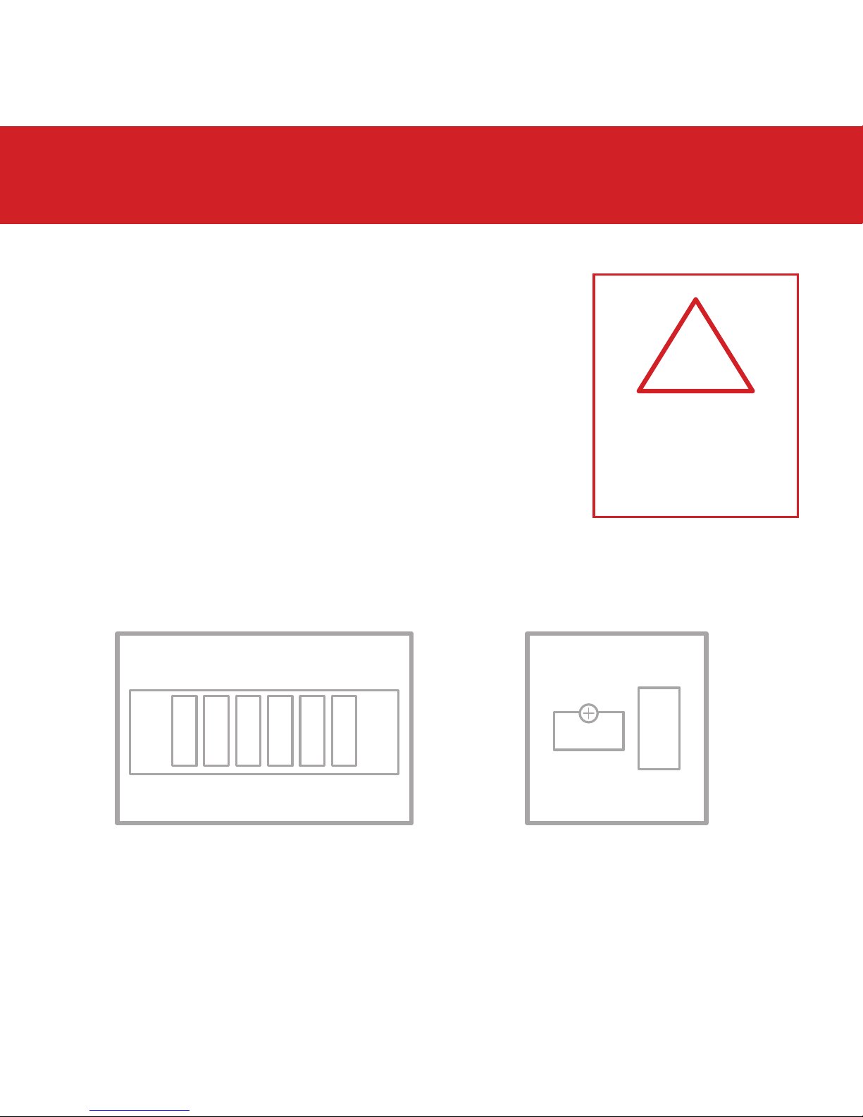
1. Switch off mains power
You will be installing Thermotouch as part
of a high voltage mains electrical circuit.
To ensure your safety and to protect the
thermostat, switch off the mains power
before you start the installation.
Fuse Box Fused Switch
CAUTION
High Voltage
Cables
!

7
Installing Thermotouch
2. Choose a location
At this stage it its likely that an electric
underfloor heating system has been
installed and a back box is already in place.
The underfloor heating cold tail should
be pulled up through the back box, and
the sensor probe installed (in the conduit
provided) within the wall cavity or pre
chased channel in a solid wall.
8
Installing Thermotouch
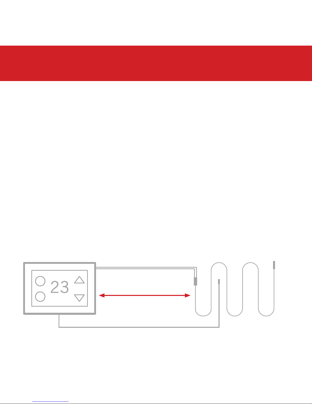
3. Maximum distances
Thermotouch can be installed up to 50m
away from the underfloor heating system it
is controlling, provided that the floor sensor
is used to control the temperature.
Underfloor heating cold tails and floor
sensor probes can be extended up to 50m.
50m max.
9
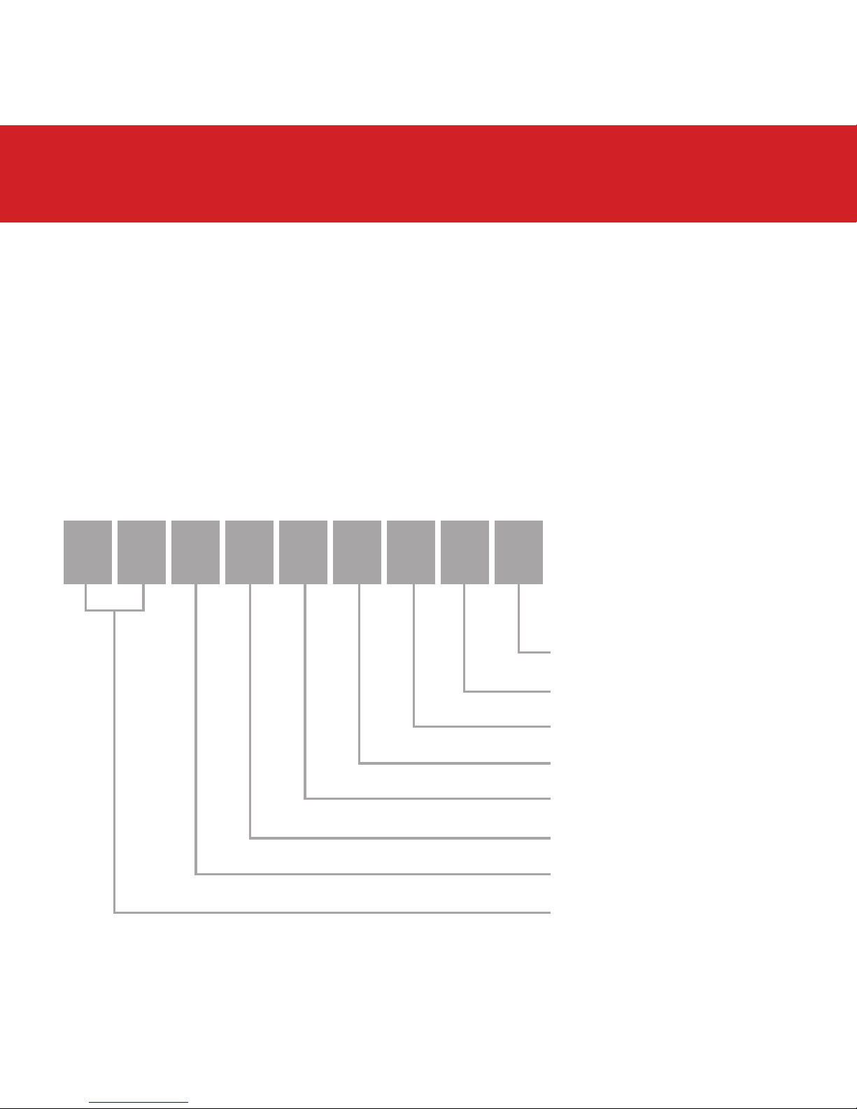
Installing Thermotouch
UFH Live
UFH Neutral
Appliance Neutral
230V AC Supply Neutral
230V AC Supply Live
Appliance Live
Common Earth (Ground)
Sensor connections
4. Wiring diagram
Connect Thermotouch to the underfloor heating
(UFH) cold tail, additional appliance, power
supply and floor temperature sensor.
The floor temperature sensor is not polarity sensitive.
9 8 7 6 5 4 3 2 1
 Loading...