

ThermoTex Nagel GmbH
Schutterstr. 14, 77746 Schutterwald, GERMANY
Phone +49 781 9616-0, fax +49 781 9616-50
info@thermo-tex.de, www.thermo-tex.de
Operating manual for
TT5-L
- Translated version of the original operating manual -

Table of contents
This document is the translated version of the original German
operating manual. For any translations into other languages, the
original German manual must be used as a basis. You can obtain the
original manual from ThermoTex.
6.3.1
6.3.2
6.3.3
6.10.1
6.10.2
6.10.3
6.10.4
7.2.1
7.2.2
CONTENTS
1 Product description ............................................................................................................... 4
1.1 Product Specifications ............................................................................................................................... 4
1.2 Conformity................................................................................................................................................. 4
1.3 Environment .............................................................................................................................................. 4
1.4 Content ..................................................................................................................................................... 5
2 Safety instructions ................................................................................................................. 6
2.1 Basic safety measures for normal operation.............................................................................................. 6
2.2 Basic safety measures for maintenance and servicing .............................................................................. 6
3 General informations ............................................................................................................. 6
3.1 Caution ..................................................................................................................................................... 6
4 Device Overview .................................................................................................................... 7
4.1 Front View ................................................................................................................................................. 7
4.2 Rear View ................................................................................................................................................. 7
4.3 Bottom View .............................................................................................................................................. 8
4.4 The Internal View of Printer ....................................................................................................................... 9
4.5 The Printing Mechanism.......................................................................................................................... 10
5 Printer Setup ........................................................................................................................ 11
5.1 Open the Printer ...................................................................................................................................... 11
5.2 Loading the Ribbon ................................................................................................................................. 12
5.3 Loading the Label Roll Module ................................................................................................................ 17
5.4 Connecting the Printer to the Host Computer .......................................................................................... 19
5.5 Printer Driver installation ......................................................................................................................... 21
6 Printer setting and control ................................................................................................... 23
6.1 Operation Panel ...................................................................................................................................... 23
6.2 LCD Interface Introduction ...................................................................................................................... 24
6.3 LCD Interface Function ........................................................................................................................... 25
Main Page ................................ ................................................................ ................................ 25
Device Page ............................................................................................................................. 25
Menu Structure ......................................................................................................................... 26
6.4 Keyboard Mode ....................................................................................................................................... 28
6.5 Label Calibration and Self Test ............................................................................................................... 29
6.6 Self Test .................................................................................................................................................. 29
6.7 Label Calibration Button .......................................................................................................................... 30
6.8 Error Alerts .............................................................................................................................................. 31
6.9 Operation Panel Status: ................................................................ ................................ .......................... 31
6.10 USB Host ............................................................................................................................................ 33
Usage of Extended Memory ..................................................................................................... 33
Usage of Firmware Update ....................................................................................................... 34
USB Keyboard.......................................................................................................................... 34
Scanner .................................................................................................................................... 34
6.11 Dump Mode Begin .............................................................................................................................. 34
7 Accessories.......................................................................................................................... 35
7.1 Preparation Steps ................................................................................................................................... 35
7.2 Installing the Cutter ................................ ................................................................ ................................ . 37
Installing the Cutter................................................................................................................... 37
Installing the Label Roll Module on the Printer .......................................................................... 40
BA_TT5-L_GB_V(0).DOCX page 2

Table of contents
8 Maintenance and adjustment............................................................................................... 41
8.1 Cleaning the Print Head ................................ ................................................................ .......................... 41
8.2 Troubleshooting ...................................................................................................................................... 42
8.3 Communication port specifications .......................................................................................................... 43
9 Bluetooth Setting ................................................................................................................. 44
9.1 Steps for setting Bluetooth keyboard ....................................................................................................... 44
9.2 Steps for setting Bluetooth connection on the LCD panel ........................................................................ 45
9.3 Introduction of the Bluetooth parameters ................................................................................................. 47
10 Spare parts list ..................................................................................................................... 47
BA_TT5-L_GB_V(0).DOCX page 3
Product description
WARNING
This is a Class A product. In a domestic environment this product may cause radio
interference in which case the user may be required to take adequate measures.
Old appliances contain valuable recyclable materials that are to be recycled.
Dispose of separately from residual waste at suitable collection points.
The modular design of the printer makes it easy to break it down into its components.
Parts should be recycled.
The electronic board of the device is equipped with a lithium battery.
Disposal in used battery collection containers of the trade or with the public disposal
carriers.
1 Product description
1.1 Product Specifications
Print Method Thermal Transfer / Direct Thermal
Resolution 203 dpi (8 dots/mm)
Print Speed 7 IPS (177 mm/s)
Print Width 4.25” (108 mm)
Print Length Min. 0.16” (4 mm)
Max. 68” (1727 mm)
Length 11.0” (280 mm)
Dimension Height 7.7” (195 mm)
Width 8.3” (210 mm)
Weight 5.9 lbs (2.7 Kg) ,excluding consumables
Interfaces
USB 2.0 for PC Connection (B-Type), RS232C (D-Sub 9 pin),
IEEE 802.3 10/100 Base-Tx Ethernet port (RJ-45), USB Host (A-Type),
Parallel Port (Mini-Centronics)
Power Auto Switching 100-240V AC, 50-60Hz
Environment Operation Temperature 41°F to 104°F (5°C to 40°C)
Storage Temperature -4°F to 140°F (-20°C to 60°C)
Humidity Operation 25-85%, non-condensing.
Storage 10-90%, non-condensing
1.2 Conformity
EN 55032:2012 / AC:2013 Class A
EN 61000-3-2:2014
EN 61000-3-3:2013
EN 55024:2010
1.3 Environment
BA_TT5-L_GB_V(0).DOCX page 4
Product description
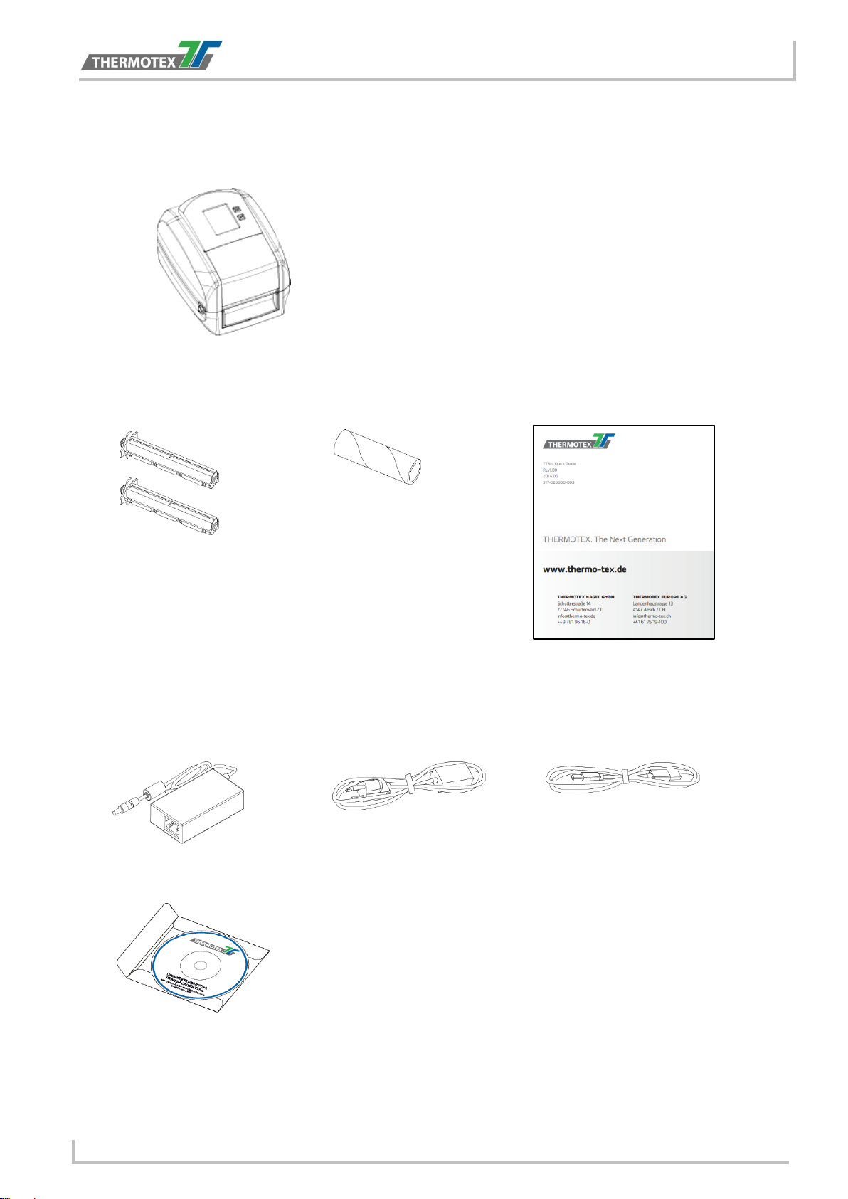
● Ribbon Hubs
Set of 2
● Ribbon Module
Empty Ribbon Core
● Quick Guide
● AC Adapter
● Power Adapter
Power Cord
● USB Cable
● CD
1.4 Content
Please check that all of the following items are included with your printer.
TT5-L Barcode Printer
BA_TT5-L_GB_V(0).DOCX page 5
Safety instructions
Keep the equipment away from humidity.
Before you connect the equipment to the power outlet, please check the voltage of the
power source.
Make sure the printer is off before plugging the power connector into the power jack.
It is recommended that you connect the printer to a surge protector to prevent possible
transient overvoltage damage.
Be careful not to get liquid on the equipment to avoid electrical shock.
For safety and warranty reasons, ONLY qualified service personnel should open the
equipment.
Do not repair or adjust energized equipment under any circumstances.
Danger of explosion if battery is incorrectly replaced. Replace only with the equivalent type
recommended by the manufacturer.
Dispose of used batteries according to the manufacturer’s instructions.
Only use with designated power supply adapter model.
Changes or modifications not expressly approved by the party responsible for compliance
could void the user's authority to operate the equipment.
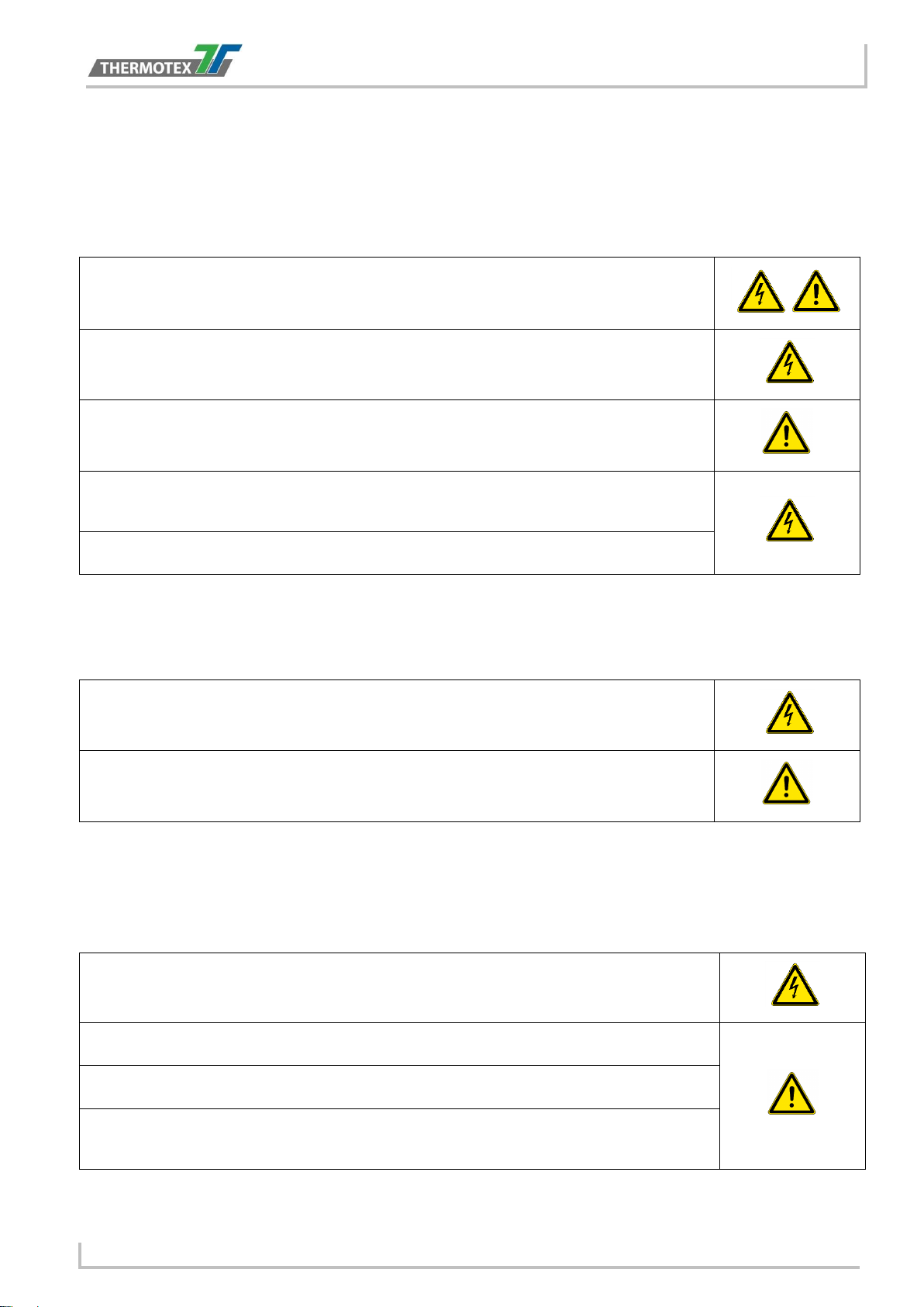
2 Safety instructions
Please read the following instructions carefully.
2.1 Basic safety measures for normal operation
2.2 Basic safety measures for maintenance and servicing
3 General informations
3.1 Caution
Specifications are subject to change without notice.
BA_TT5-L_GB_V(0).DOCX page 6

Device overview
PRINTER COVER
POWER BUTTON
FEED BUTTON
TOUCH PANEL
FRONT COVER
COVER RELEASE CATCHES
Pull catches for opening the printer cover
FAN-FOLD LABEL INSERT
Feed slot for outside continuous labels
PARALLEL PORT
USB HOST
ETHERNET PORT
SERIAL PORT
USB PORT
POWER JACK
CALIBRATION
4 Device Overview
4.1 Front View
4.2 Rear View
BUTTON
BA_TT5-L_GB_V(0).DOCX page 7
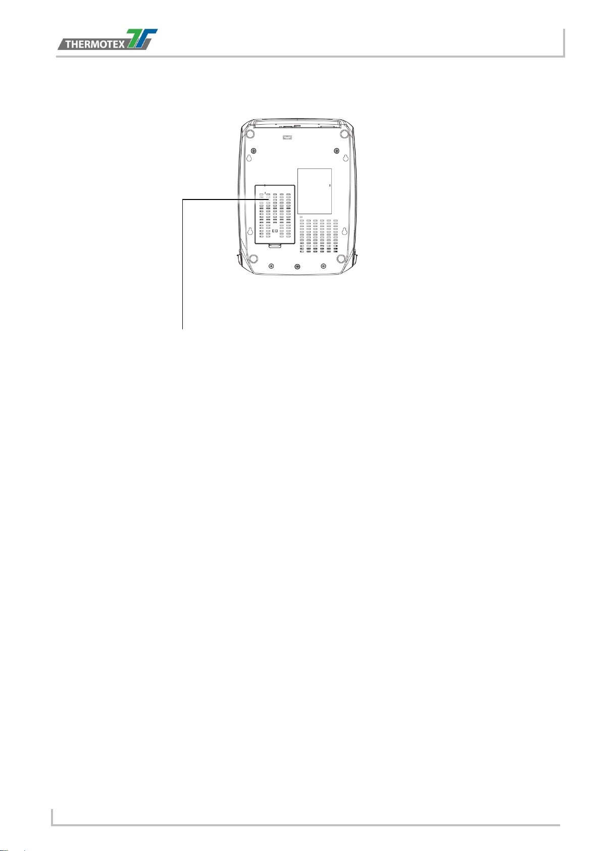
4.3 Bottom View
COVER OF THE MODULE CONNECTION JACKS
Device overview
BA_TT5-L_GB_V(0).DOCX page 8
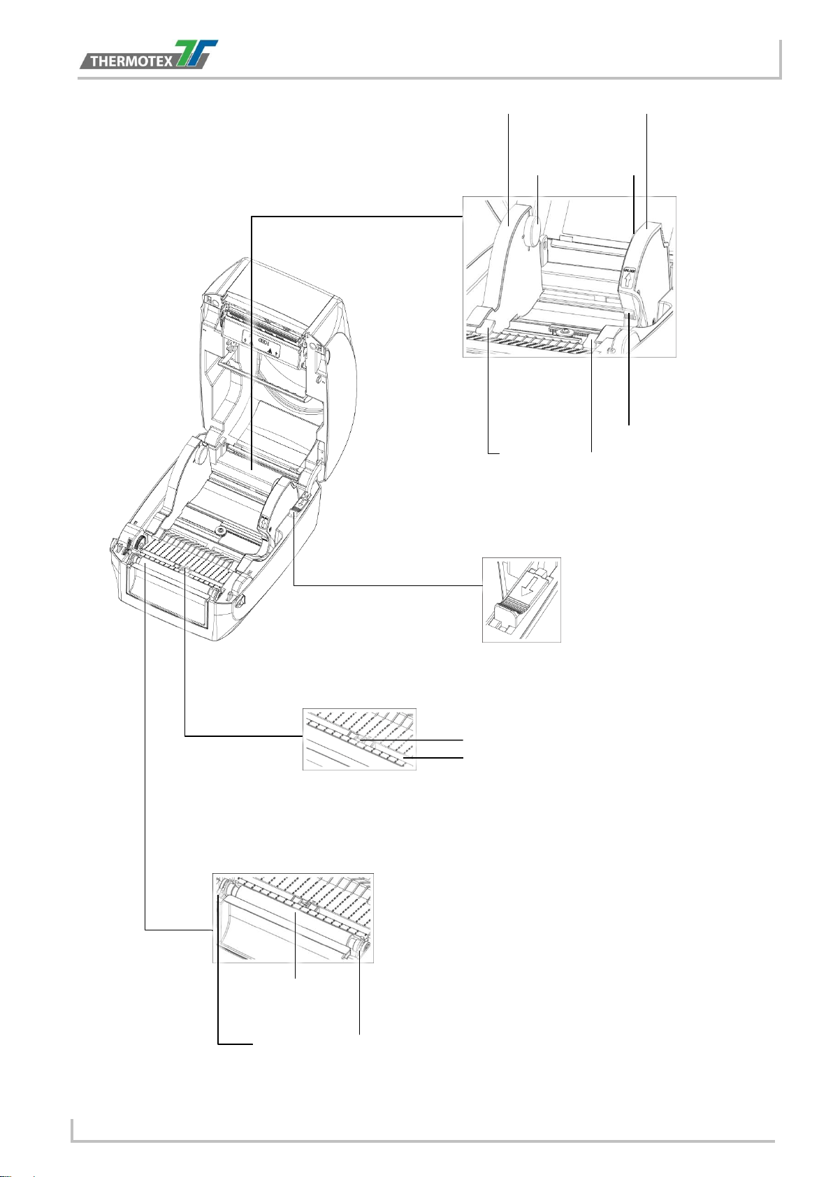
Device overview
LABEL
MODULE
LABEL GUIDE PLATE
LABEL SUPPLY HUB
LABEL GUIDE
RELEASE CATCH
supply hub
RELEASE CATCH
closing the printer cover
LABEL SENSOR
GUIDE TRACK
LABEL SENSOR
PLATEN MODULE
PLATEN
PLATEN LOCKERS
4.4 The Internal View of Printer
SUPPLY
Release catch for
opening the label
Release catch for
BA_TT5-L_GB_V(0).DOCX page 9
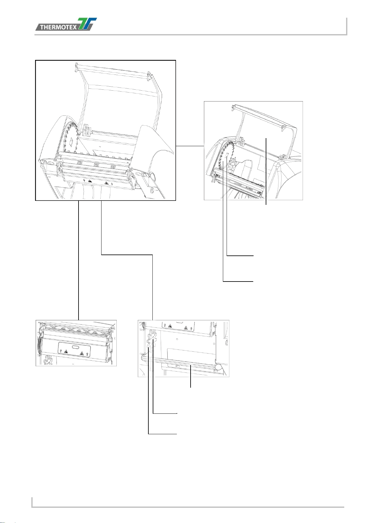
Device overview
RIBBON REWIND MECHANISM
COVER
NOTCH OF RIBBON
RIBBON REWIND WHEEL
PAPER PRESS BAR
NOTCH OF RIBBON SUPPLY WHEEL
RIBBON SUPPLY WHEEL
RIBBON
PRINT HEAD
4.5 The Printing Mechanism
The cover for Ribbon rewind
mechanism
REWIND WHEEL
SUPPLY
MECHANISM
BA_TT5-L_GB_V(0).DOCX page 10

Printer Setup
COVER RELEASE CATCHES
Pull the catches toward the direction
Pull the catches toward the direction
The printing mechanism is lifted up with the
5 Printer Setup
5.1 Open the Printer
Open the Printer Cover and the Printing Mechanism
Place the printer on a flat surface. Open the printer cover by pulling the cover release catches on both sides of
the printer and lift the printer cover.
Pull the catches for opening the printer cover
printer cover
BA_TT5-L_GB_V(0).DOCX page 11

Loading the Ribbon
A NEW RIBBON
EMPTY RIBBON CORE
RIBBON HUB
Stick on empty ribbon core
Insert the ribbon hub
Wind the ribbon around the core
RIBBON REWIND
RIBBON SUPPLY
A NEW RIBBON MODULE
5.2 Loading the Ribbon
A New Ribbon Module Installation
1. Attach the ribbon to the empty ribbon core with the adhesive strip at the end of the ribbon.
2. Insert the ribbon hub into empty ribbon core and new ribbon. Wind the ribbon around the empty ribbon
core for 2 to 3 circles.
3. A ribbon module is assembled as below.
BA_TT5-L_GB_V(0).DOCX page 12

Loading the Ribbon
RIBBON SUPPLY MECHANISM
NOTCH OF RIBBON SUPPLY WHEEL
RIBBON SUPPLY WHEEL
RIBBON SUPPLY
MODULE
HOLDER
NOTCH OF
WHEEL
HOLDER
NOTCH
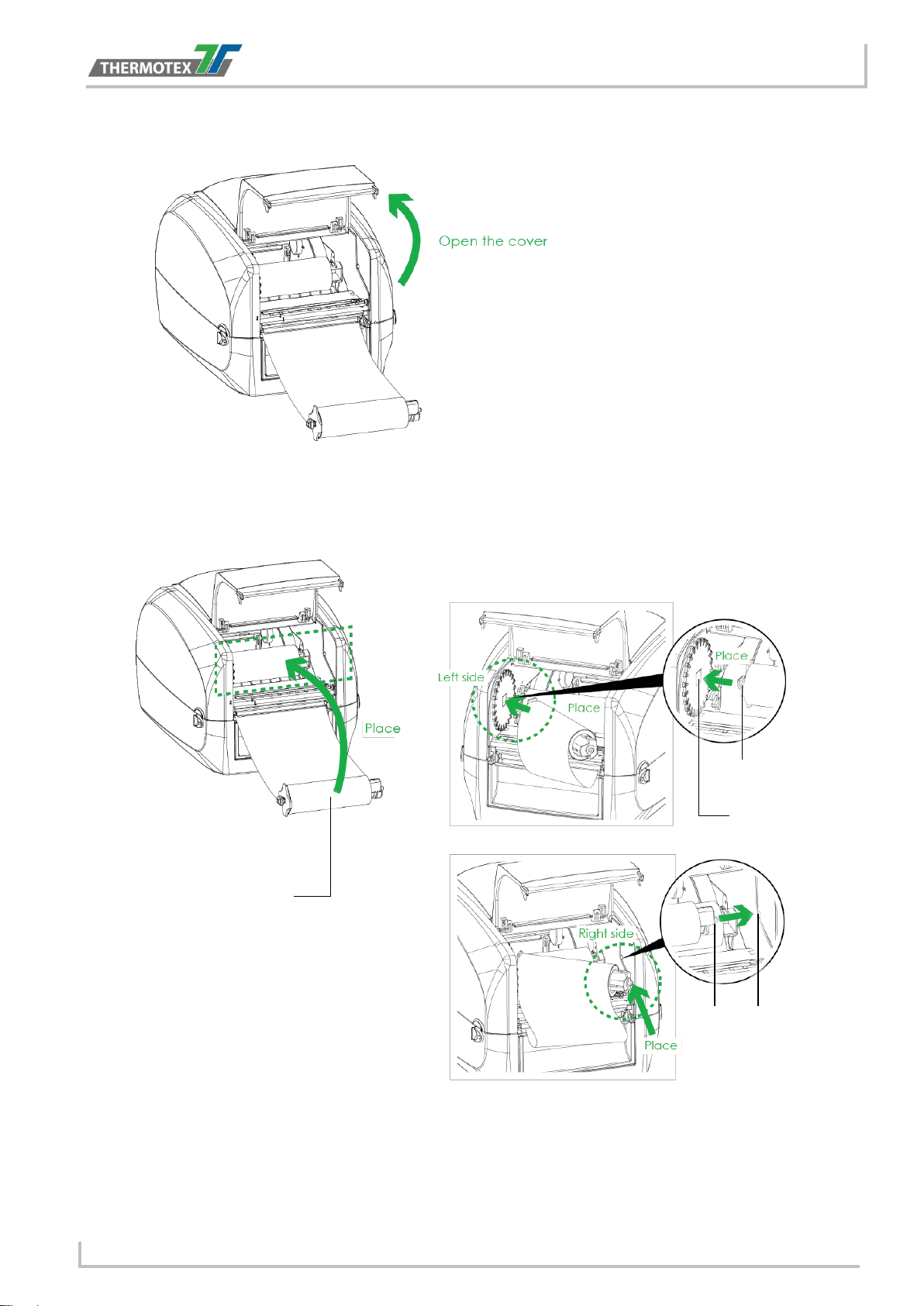
Load the Ribbon on the Printer for Ribbon Supply Module
4. Place the ribbon supply module into the printing mechanism. Please the left-hand side of ribbon hub first.
Make sure the holder of ribbon hub is inserted into the notch. Then place the right-hand side of ribbon
hub.
RIBBON SUPPLY
BA_TT5-L_GB_V(0).DOCX page 13
Loading the Ribbon
RELEASE CATCH
COVER
mechanism
RIBBON REWIND MECHANISM
NOTCH OF RIBBON REWIND WHEEL
RIBBON REWIND WHEEL
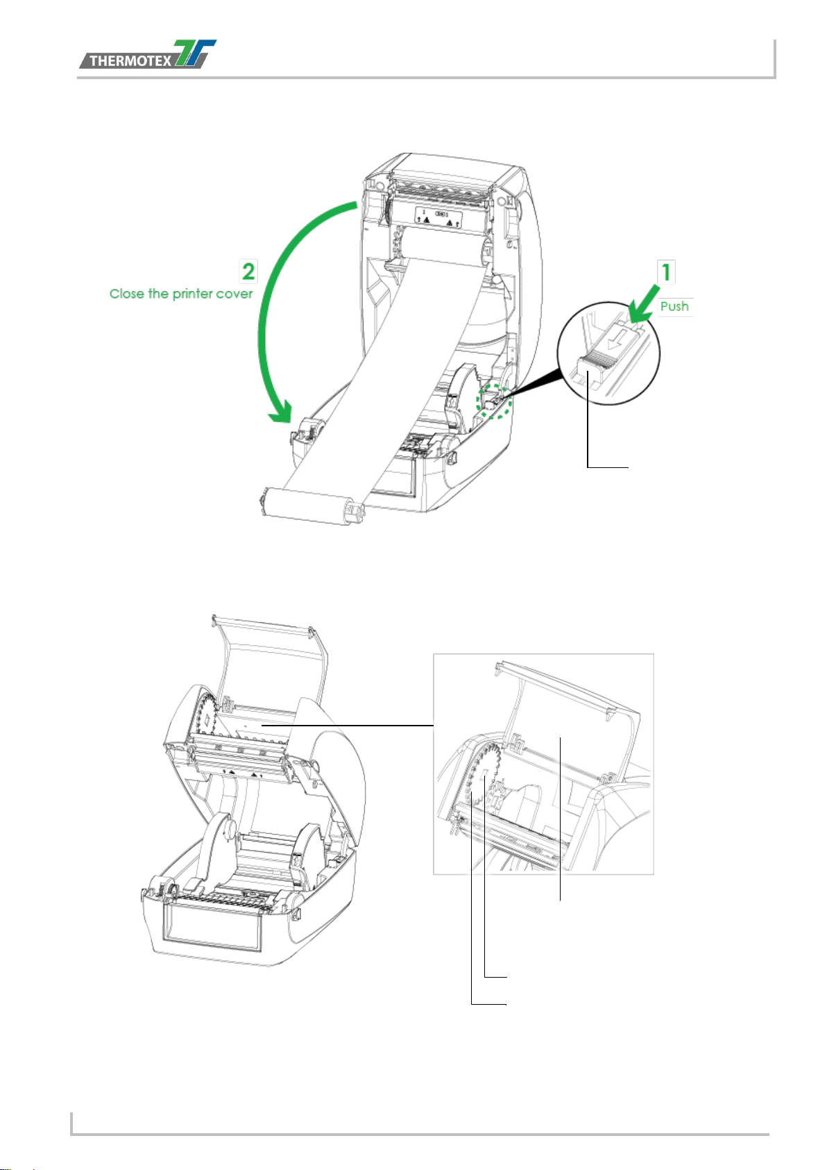
5. Unlock the release catch to close the printer cover. Push the release catch forward to unlock it. The
ribbon supply module loading is completed.
Release catch for closing
the printer cover
Load the Ribbon on the Printer for Ribbon Rewind Module
The cover for Ribbon rewind
BA_TT5-L_GB_V(0).DOCX page 14
Loading the Ribbon
RIBBON REWIND
NOTCH OF RIBBON
HOLDER
HOLDER
NOTCH
6. Open the cover of ribbon rewind mechanism.
7. Place the ribbon rewind module into the ribbon rewind mechanism. Please the left-hand side of ribbon
hub first. Make sure the holder of ribbon hub is inserted into the notch. Then place the right-hand side of
ribbon hub.
REWIND WHEEL
MODULE
BA_TT5-L_GB_V(0).DOCX page 15

Loading the Ribbon
RIBBON REWIND WHEEL
8. Turn the ribbon rewind wheel to tighten the ribbon until it has no wrinkles.
9. Close the cover of ribbon rewind mechanism. The ribbon loading is completed once the ribbon supply
module and ribbon rewind module are assembled correctly.
BA_TT5-L_GB_V(0).DOCX page 16

5.3 Loading the Label Roll Module
LABEL STOCK
LABEL
LABEL GUIDE PLATE
LABEL SUPPLY HUB
LABEL GUIDE
RELEASE CATCH
LABEL GUIDE
PLATE
RELEASE CATCH
Release catch for opening the label supply
hub
Loading the Label Stock on the Printer
1. Unlock the ribbon catch and pull to open the label guide plate.
Place the label stock on label supply hubs. Make sure the label stock is aligned to both hubs. Adjust the label
guide plates to fix the label width. Remember to push the release catch when moving the label guide plates.
Loading the Label Roll
SUPPLY
MODULE
Release catch for
opening the label
supply hub
BA_TT5-L_GB_V(0).DOCX page 17

Loading the Label Roll
LABEL GUIDE
RELEASE CATCH
closing the printer cover
2. Feed the Label through the label guides. The label guides will help to prevent the label swaying.
3. Unlock the release catch to close the printer cover.
Release catch for
4. Press the FEED key and make sure the label is fed smoothly. The label loading is completed now.
NOTE: * Please keep the rack gear clean to ensure the smoothness of label holder.
BA_TT5-L_GB_V(0).DOCX page 18

Connecting to the Computer
POWER CORD
AC ADAPTER
POWER ADAPTER
TT5-L
JACK
SLOT
PLUG
SOCKET
THE WALL
5.4 Connecting the Printer to the Host Computer
1. Please make sure that the printer is switched off.
2. Connect the power cord to the AC adapter.
Connect the jack of the power adapter to the printer and connect the plug of the power
adapter to the socket of the wall.
BA_TT5-L_GB_V(0).DOCX page 19

Connecting to the Computer
USB CABLE
PLUG
PLUG
USB PORT
PC
SOCKET
TT5-L
TOUCH PANEL LCD
3. Connect the USB/serial cable to the printer and host computer.
4. Press the power button. The Touch Panel LCD will light up.
BA_TT5-L_GB_V(0).DOCX page 20

Printer Driver installation
5.5 Printer Driver installation
1. From the Driver CD launch the Application
2. Select “I accept the terms in the license agreement”, and click ”Next”,then click ”Finish” to next step
3. The Driver Wizard will guide you through the installation procedure. Select "Install printer drivers" and
click “Next”.
BA_TT5-L_GB_V(0).DOCX page 21

Printer Driver installation
4. With a USB connection, search models such as the right diagram printer device. Specify your printer
model and click ”Next”.
5. Enter the printer name (you can use default), then click "Next" to display as right diagram. Click "Finish"
button to start installation.
6. Driver installation completed
BA_TT5-L_GB_V(0).DOCX page 22

Printer setting and control
OPERATION TOUCH PANEL
POWER
FEED
TOUCH PANEL
6 Printer setting and control
6.1 Operation Panel
POWER Button
Press the POWER button to turn on the printer, and the START UP SCREEN appears. The printer is on “ready
to print” status, the LCD screen should display the message “READY“ on the screen. When printer is turned on,
hold and press down the POWER button for 3 second will turn the printer off.
FEED Button
When you press the FEED button, the printer will advance media until the FEED button is released. If you are
using continuous labels, pressing the FEED button will advance a length of media until the button is released. If
you are using media with gaps, pressing the FEED button once will advance only one label. If the label does not
stop at the correct position, you need to run the auto-detection function for your media, please see Section 3.4
Label Calibration and Self-Test.
PAUSE PRINTING_FEED Button
Pressing the FEED button during printing will interrupt printing, and the LCD display message “PAUSE...”. When
the FEED button is pressed again, the printer resumes printing. Example: While a 10-label print job is running,
you press the FEED button to pause the printer. Two of the labels have been printed. To resume printing and
print the remaining eight labels, you will need to press the FEED button again.
CANCEL PRINTING_FEED Button
Press and hold the FEED button for 3 seconds during printing, the current print job will be cancelled. Example:
While a 10-label print job is running, you press the FEED button. Two of the labels have been printed. The print
job is cancelled and the remaining eight labels will not be printed.
BUTTON
BUTTON
BA_TT5-L_GB_V(0).DOCX page 23

Printer setting and control
Power on
6.2 LCD Interface Introduction
Getting Started
Press the POWER button to turn on the printer, and the START UP SCREEN appears.
If the printer is on “ready to print” status, the LCD screen should display the message “Ready“ on the screen.
Use touch gestures to get around the main screen and other screen for setting.
Tap the screen with your finger when you want to select on screen items such as settings icons.
On the Ready Page, three functions mode for setting. You can make various setting functions in FUNCTIONAL
MODE.
Main Wizard Test
To finish setting tap to return to Ready screen.
If you don’t want to save any changes, tap system to return to
the Ready screen.
Unlock
Lock
If printer functions are locked, printer settings cannot be overwritten
by WinTexx or any devices.
BA_TT5-L_GB_V(0).DOCX page 24

LCD Interface Function
6.3.1
6.3.2
6.3 LCD Interface Function
Main Page
Setting items for printer, ex. Printing speed, darkness. Also
includes a Printing Wizard for your ease of printing.
10 languages for printer setting
It consists of a table of values that describes the character set for
a particular language
Setting items for printing label, ex. Rotation, Printing position
offset
Providing Buzzer, Option Setting, Smart Backfeed, Serial Part
Setting, LAN Setting, LCD Setting, Clock Setting, WiFi Setting,
and Bluetooth Setting
Self- Diagnose functions for printer, ex. Calibration, Self-Test
page and Clear Memory
Recall Label and preview label
Device Page
Setting off or on for buzzer
Setting items for options, ex. Cutter, Label Dispenser,
Applicator
Setting programing language
Setting items for Serial Port, ex. Baud Rate, Parity , Data Bits,
Stop Bits
Setting items for LAN, ex. DHCP, IP Address, Subnet Mask,
Gateway
Setting for LCD, ex. off or on for Password function, Correction
Setting items for Clock, ex. Year, Month, Day, Hour, Minute and
off or on for Visible function
BA_TT5-L_GB_V(0).DOCX page 25

6.3.3
Printer Settings
Darkness
0-19
Speed
2-7
Sensor Select
Auto Select
See-Through
Reflective
Media Type
Label with Gaps
Label with Marks
Continuous
Printing Mode
Direct Thermal
Thermal Transfer
Tear-off Position
0-40
Top of Form
OFF
FULL
Door Open Only
Back Up Only
LCD Language
English
Deutsch
Francais
Espanol
Italiano
簡體中文
繁體中文
Türkce
日本語
Pусский
Code Page
850
852
437
860
863
865
857
861
862
855
866
737
851
869
Windows 1252
Windows 1250
Windows 1251
Windows 1253
Windows 1254
Windows 1255
Windows 1257
Label Settings
Rotation
0°-90°- 180°- 270°
X-Offset
-864 ~+864
Y-Offset
-400 ~+400
Start Offset
-100 ~+100
BA_TT5-L_GB_V(0).DOCX page 26
LCD Interface Function
Menu Structure

Devices
Buzzer
OFF
ON
Options
None
Option Setting
Cutter
Label Dispenser
Applicator
Smart
Backfeed
OFF
ON
Baud Rate
4800
9600
19200
38400
57600
115200
Serial Port Setting
Parity
None
Odd
Even
Data Bits
7
8
Stop Bits
1
2
LAN Setting
DHCP
OFF/ON
IP Address
0.0.0.0
Subnet Mask
255.255.255.0
Gateway
192.168.0.254
Port N°
9100
LCD Setting
Password
OFF/ON
Correction
Clock Setting
Year
Month
Day
Hour
Minute
Visible
OFF/ON
Printer Control
Test
Configuration
Directory
TPH Testing
Dump Mode
Sample pattern
Self-Test page / Balance
Select Memory
Internal / External
Clear Memory
Label Formats
Graphics
Bitmap Fonts
True Type Fonts
Asian Fonts
Printer Info
Calibration
Reset
To default
Wizard
Darkness
0-19
Speed
2-7
Media Type
Label with Gaps
Label with Marks
Continuous
X-Offset
-864 ~+864
Y-Offset
-100 ~+100
BA_TT5-L_GB_V(0).DOCX page 27
LCD Interface Function

Keyboard Mode
6.4 Keyboard Mode
When plug-in an USB keyboard to the printer, LCD touch panel will display “Enter Standalone”, press the “Y” or
“ENTER” key on keyboard to entering to the dialog for “Keyboard Mode” operation.
Recall Label
From the “Ready” page, tap to Main page.
From the Main page tap Recall Label to
Recall Label page.
From the Recall Label Page the touch panel shown on all labels.
The Data processing time will be extend as long as the labels increase.
Tap up to choose labels.
Tap down to choose labels.
Select label and print out selected label
BA_TT5-L_GB_V(0).DOCX page 28

Label Calibration
6.5 Label Calibration and Self Test
Label Calibration
The printer can automatically detect and store label height.
That means the host computer does not need to transmit the label height to the printer.
6.6 Self Test
Self-test function lets you check whether the printer is functioning normally.
Here is how you run the label size calibration and self-test.
1. Check that the label stock is loaded correctly.
2. Turn off the printer and pressing the FEED button.
3. Turn the printer on again, keeping the FEED button pressed. When the LCD displays Ready Screen,
release the FEED button. The printer will now measure the label stock and store the label height.
4. Once the printer has successfully measured the label stock, it will print a self-test label.
The contents of a self-test printout are listed below.
BA_TT5-L_GB_V(0).DOCX page 29

Label Calibration
Press and hold about
1 ~ 2 seconds
CALIBRATION BUTTON
6.7 Label Calibration Button
A hardware button to make a Label Calibration while printer encountering ‘’Media Error’’ during the cases when
first-time printer start up or change label to another type, such as change using gap label to continuous or black
mark labels.
Press Calibration button for 1 ~ 2 seconds, it will make an auto-sensing to calibrate the label’s parameters.
NOTE: *Press Calibration button is equivalent to the auto-sensing command ‘’~S,SENSOR’’ that will cancel onprinting-job and make the Label Calibration immediately.
**It can also be launched through following Menu: Main => Printer Control => Calibration
BA_TT5-L_GB_V(0).DOCX page 30

Operation Panel Status
OPERATION TOUCH PANEL
POWER
FEED
TOUCH PANEL
Type
Beeps
Description
Solution
Door Open Only
2 x4 beeps
The printing mechanism is
not correctly closed.
Open the print
mechanism and close it
again.
TPH Over Heat
None
High temperature at the print
head.
Once the print head has
cooled down, the printer
switches to standby
mode.
6.8 Error Alerts
In the event of a problem that prevents normal functioning of the printer, you will see an error message on LCD
screen and hear some beep signals. Please refer to below table for the error alerts.
BUTTON
BUTTON
6.9 Operation Panel Status:
BA_TT5-L_GB_V(0).DOCX page 31

Operation Panel Status
Ribbon Error
2 x 3 beeps
No ribbon is installed and the
printer displays an error.
Make sure that the printer
is set to direct thermal
printing mode.
The ribbon is finished or the
label supply hub is not
moving.
Replace the ribbon roll.
Media Error
2 x 2 beeps
No paper is detected.
Make sure that the label
sensor is positioned
correctly.
If the sensor still does not
detect the paper, run the
auto- detection function
again
Paper is finished.
Replace the label roll.
Printer feed problem.
Possible reasons: the
printer medium has
become trapped around
the rubber roll; the sensor
cannot detect a gap or
black mark between the
labels; there is no paper.
Please reset the sensor.
File Error
2 x 2 beeps
The memory is full. The
printer prints the message
« File System full ».
Delete unnecessary data
or install additional
memory.
Unable to find file. The
printer prints the message
« File not found »
Use the « ~X4 »
command to print all files.
Then check whether the
files exist and whether the
names are correct.
BA_TT5-L_GB_V(0).DOCX page 32

Operation Panel Status
6.10.1
File Error
2 x 2 beeps
A file of the same name
already exists. The printer
prints the message
« Duplicated Name ».
Change the name of the
file and try storing it again.
6.10 USB Host
Definition: USB Host port supports either device: USB memory stick, USB keyboard or scanner.
Purpose
USB memory stick: It extends the user memory space for Graphic, Font, Label Format, DBF and
Command files downloading. The printer’s Firmware can also be updated by copying a new version of
Firmware into USB memory stick.
Connecting an USB keyboard to printer for ‘’Keyboard Mode’’ mode operation.
Plug-in an USB scanner to operate the printer in ‘’Keyboard Mode’’.
USB memory stick : It supports hot-plugging function; printer will create a Folder ‘’\LABELDIR’’ and switch
Usage of Extended Memory
‘’User Flash’’ to ‘’ Extended Memory‘’ automatically while user plugs an USB memory stick into the
printer.
BA_TT5-L_GB_V(0).DOCX page 33

Operation Panel Status
6.10.2
6.10.3
6.10.4
Remove USB memory stick from printer and plug-in it to a PC’s USB port.
Copy a new version of Firmware ‘’xxxx.bin’’ to the Folder ‘’\LABELDIR\FW’’
Remove USB from PC and plug-in back to the printer. The printer will update the Firmware automatically
The "\ LABELDIR \ FW" directory allows only one file exists, if there are multiple files, the files will be
Don’t remove the USB memory stick out while it’s under updating with ‘’Flash Writing...’’message that
When plug-in an USB keyboard to the printer, LCD touch panel will display “Enter Standalone”, press the
By connecting a USB keyboard to the printer, if you don’t want to enter the Standalone mode, press the
After leaving the keyboard mode, for re-entry, press the keyboard "F1" key or reboot to display “Enter
When plug-in an USB scanner to the printer, LCD touch panel will display “Enter Standalone”, tap the
Usage of Firmware Update
confused.
displays on LCD panel.
USB Keyboard
“Y” key on keyboard to entering “Keyboard Mode” operation. In this mode you can perform "Recall Label",
set "Country Code", "Code Page", "Clock Setting", "Database Setting" and "Label Edit".
"N" key to leave. To leave Standalone mode operation, press "ESC" key to exit.
Standalone”.
Scanner
“Feed” Key to entering “Keyboard Mode” operation.
Note
The USB Host port on printer does not support ‘’USB HUB’’ function.
The USB Memory Stick supports with ‘’FAT32’’Disk Format and up to 32GB only. The certified venders
are Transcend, Apacer, ADATA, Patriot, Corsair and Kingston.
The USB Memory Stick only supports download through the printer, On a PC, user may copy entire folder
“\LABELDIR” from USB memory stick to PC or vice-versa. You can’t copy the data to USB Memory Stick
via PC individually.
*External USB Host port is for power 500 mA, is not recommended as electronics charging use.
6.11 Dump Mode Begin
For make sure provide us correct information for check what commands sent from the PC or software, please
following below steps,
STEP 1: Let the printer enter Dump Mode
Here is how you switch to dump mode:
On the Ready Page, three function mode for setting. You can make various setting functions in FUNCTIONAL
MODE.
1. Tap ‘’Main‘’ on LCD menu
2. Tap ‘’Printer Control‘’
3. It will show Printer Control setting items such as Configuration--→Directory--→TPH Testing--→Dump
Mode
Please select to Dump Mode.
STEP 2: Make sure printer ready for print a label
STEP 3: Send a label or commands which met problem to the printer
STEP 4: Printer will print out a label with letters and numbers, please take a picture on them and send us by
email.
To cancel (get out of) the Dump Mode, please press the FEED key, and then the printer will
automatically print “OUT OF DUMP MODE.” This indicates that the printer is back to the standby mode.
BA_TT5-L_GB_V(0).DOCX page 34

Accessories
FRONT COVER
7 Accessories
7.1 Preparation Steps
Before installing the cutter, please make some preparations as follows.
1. Turn off the printer:
Remember to switch off the printer before installing any module.
And also remove the power supply.
2. Open the printer cover and the printing mechanism:
Open the printer cover by pulling the release catches on both sides of the printer and lift the cover.
3. Remove the front cover:
Please pull upward to remove the front cover.
BA_TT5-L_GB_V(0).DOCX page 35

Accessories
CLIP
PLATEN MODULE
4. Remove the platen :
Lift up the release clips on both sides of the platen to release and pull upward the platen.
5. Ribbon loading:
Please see the Section 5.2 for further information about Loading the Ribbon.
6. Label loading
Please see the Section 5.3 for further information about Loading the Label Roll Module.
BA_TT5-L_GB_V(0).DOCX page 36

Cutter Installation
7.2.1
CONNECTION CABLE OF CUTTER
FEED-OUT SLOT
COVER
SLOT
7.2 Installing the Cutter
Preparation Steps
Please see the Section 7.1 Preparation Steps to complete the preparation steps before installing the cutter.
The Overview of the Cutter
Installing the Cutter
1. Pass the connection cable through the slot of the printer.
NOTE:
* Remember to switch off the printer before installing the cutter.
** Do not use to cut adhesive labels! Glue residue will be left on the cutter blade and impair its functioning.
*** You can cut paper with a max. width of 100mm.
**** With the cutter installed, set the stop position in WinTexx to 33.
BA_TT5-L_GB_V(0).DOCX page 37

Cutter Installation
CLIP
RELEASE CATCH
2. Place the cutter to align both holes of screw and then tighten the screws.
(Screw holes on the front side of the bottom barcode Printer)
3. Place the platen back to the printer and lock the clips.
4. Close the printer cover and printing mechanism.
Then turn the printer upside down.
Release catch for
closing the printer
cover
BA_TT5-L_GB_V(0).DOCX page 38

Cutter Installation
COVER OF THE MODULE CONNECTION JACKS
JACK
CONNECTOR OF THE CONNECTION
COVER OF THE MODULE CONNECTION JACKS
CUTTER JACK
LABEL DISPENSER JACK
5. Open the cover on the bottom of printer.
6. Plug the connector for the cutter to the jack.
7. Close the cover of the module connection jacks.
NOTE:
* The printer must be switched off, or the motherboard may be destroyed!
** There are 5 jacks: the lower jack for the label dispenser, the upper jack for the cutter. And additionally Real
Time Clock, Bluetooth and Wi-Fi.
BA_TT5-L_GB_V(0).DOCX page 39

Cutter Installation
7.2.2
Installing the Label Roll Module on the Printer
1. Pass the labels through the guides and the cutter.
2. Close the top cover and printing mechanism. To finish, press the FEED button to set the label position.
NOTE:
* We advise against using inside wound label stock.
** Labels should be at least 30 mm high. When using the printer with the cutter, you should set the stop position
(^E) to 33.
BA_TT5-L_GB_V(0).DOCX page 40

Maintenance
8 Maintenance and adjustment
8.1 Cleaning the Print Head
Dirt on the print head or ribbon may result in inadequate print quality (there are only partial images on the label).
The printer cover should therefore be kept closed when possible. Keeping dirt and dust away from the paper or
labels ensures a good print quality and a longer lifespan of the print head.
Cleaning Steps
1. Switch off the printer.
2. Open the printer cover.
3. Remove the ribbon.
4. To remove any label residue or other dirt from the print head (see green arrow), please use a soft lint-free
cloth dipped in alcohol to wipe.
NOTE:
* We advise to clean the print head once per week. (Recommended)
** When cleaning the print head, please do not use any sharp or hard objects!
*** Do not touch the glass safeguard of the print head with your bare hands!
BA_TT5-L_GB_V(0).DOCX page 41

Troubleshooting
Problem
Solution
The printer is switched on but the LCD screen
does not light up.
Check the power supply. (Please see the Section 5.4)
The LCD screen displays error alert and
printing is interrupted.
Check the software settings (driver settings) or command
codes.
Look for the error alert in the table in Section 6.8. Error Alerts.
Check whether the print mechanism is closed correctly.
(Please see the Section 4.5)
The label stock passes through the printer but
not image is printed.
Please make sure that the label stock is loaded the right side
up and that it is the suitable material.
Choose the correct printer driver.
Choose the correct label stock and a suitable printing mode.
The label stock jams during printing.
Clear the paper jam. Remove any label material left on the
thermal print head and clean the print head using a soft lintfree cloth dipped in alcohol. (Please see the Section 8.1)
There is no printed image on some parts of
the label.
Check whether there is any label material or ribbon stuck to
the thermal print head.
Check for errors in the application software.
Check whether the starting position has been set correctly.
Check the ribbon for wrinkles.
Check the power supply is correct.
There is no printed image on part of the label
or the image is blurred.
Check the thermal print head for dust or other dirt.
Use the internal ‘~T‘ command to check whether the thermal
print head will carry out a complete print job.
Check the quality of the print medium.
The printed image is positioned incorrectly.
Check whether there is paper or dust covering the sensor.
Check whether the label stock is suitable. Contact your
supplier.
Check the paper guide settings.
Skipping labels during printing.
Check the label height setting.
Check whether there is dust covering the sensor.
Run the auto-detection function. (Please see the Section 6.7)
The printed image is blurred.
Check the darkness setting.
Check the thermal print head for dust or dirt. (Please see the
Section 8.1)
The cutter does not cut off the labels in a
straight line.
Check whether the label stock is positioned straight.
The cutter does not cut off the labels
completely.
Check whether the label is more than 0.2 mm thick.
When using the cutter, the labels are not fed
through or cut off incorrectly.
Check whether the cutter has been correctly installed.
Check whether the paper guides are functioning correctly.
The label dispenser is not functioning
normally.
Check whether there is dust on the label dispenser.
Check whether the label stock is positioned correctly.
8.2 Troubleshooting
Please address any questions to our technical hotline in Germany
Tel.: 00 49 781/9616-36, Fax: 00 49 781/9616-30, E-Mail: hotline@thermo-tex.de
For clients from Switzerland: Tel.: 00 41 61751/9100, Fax: 00 41 61751/9101,
E-Mail: info@thermo-tex.ch
BA_TT5-L_GB_V(0).DOCX page 42

Port Specifications
Connector Type:Type B
Pin NO. 1 2 3 4 NC
D-
D+
GND
RS232 Housing (9-pin to 9-pin)
Pin NO.
1
2 3 4 5 6 7 8 9 Type
+5V, max
500mA
TXD
RXD
N/C
GND
RTS
CTS
RTS
N/C
DB9
Plug
-
RXD
TXD
DTR
GND
DSR
RTS
CTS
RI
DB9
Socket
Type: RJ45
Pin NO. 1 2 3 4 5 6 7 8 TX+
TX-
RX+
NC
NC
RX-
NC
NC
Connector Type:Type A
Pin NO. 1 2 3 4
VBUS
D-
D+
GND
8.3 Communication port specifications
Pinout Description
USB Port
Serial Port
Default Settings: Baud rate 9600, no parity, 8 data bit, 1 stop bit, XON/XOFF, Protocal and RTS/CTS
Ethernet Port
USB Host
BA_TT5-L_GB_V(0).DOCX page 43

Bluetooth Setting
Type: Centronics Female
Pin NO. 1 2 3 4 5 6 7 8 9 10
11
12
BUZY
SELECT
ACK
FAULTN
LPT
PER
DATA0
DATA1
DATA2
DATA3
DATA4
DATA5
DATA6
Pin NO.
13
14
15
16
17
18
19
20
21
22
23
24
DATA7
LPT
INTN
STROB
SELIN
AUTO
NC
GND
GND
GND
GND
GND
GND
Pin NO.
25
26
27
28
29
30
31
32
33
34
35
36
GND
GND
GND
GND
GND
GND
GND
GND
GND
GND
GND
5V
Parallel Port
NOTE:
* Serial port total output cannot exceed the maximum current of 500mA
9 Bluetooth Setting
9.1 Steps for setting Bluetooth keyboard
Step 1 Power off the printer
Step 2 Install the Bluetooth module
Note: Methods for installing Bluetooth module, please refer to Bluetooth module manual
Step 3 A grey Bluetooth icon will be displayed in the main page after switching on the printer
and it indicates that the printer has detected the Bluetooth module.
BA_TT5-L_GB_V(0).DOCX page 44

Bluetooth Setting
Activate the Bluetooth keyboard to be detectable.
Step 4 Switch on the keyboard on the left side
Step 5 Hold down F1 Button for 3 seconds => fast blinking light means the keyboard
enters pairing mode.
Step 6 Steady light for 5 seconds indicates successful pairing.
If light blinks slowly, repeat previous step.
9.2 Steps for setting Bluetooth connection on the LCD panel
Step 1 Turn on the printer and LCD panel will display home screen.
Step 2 Select “Main” Step 3 Select “Devices”
Step 4 Select “Bluetooth Settings” Step 5 Set “Profile” to “HID Mode”
and click “Search Devices”
BA_TT5-L_GB_V(0).DOCX page 45

Bluetooth Setting
Step 6 The LCD panel will display “Waiting” when the printer detects the Bluetooth keyboard.
When the Bluetooth keyboard is detected by the printer, the monitor will indicate the
information of Bluetooth keyboard.
Step 7 Press “ON” button on the LED panel to create a connection between the printer and the
Bluetooth keyboard, and then the LCD panel will display „Please enter PIN Code“
Enter the “PIN Code” into the printer via the Bluettoth keyboard.
Note: The “PIN Code” does not need to be entered if the “SPP” of the printer and the
Bluetooth keyboard is set “ON”.
Step 8 When the connection is successfully created, the current panel will be automatically
switched to the setting menu of Bluetooth, as the figure below indicates.
(The upper left corner LED of Blutooth keyboard will steady light for 5 seconds)
BA_TT5-L_GB_V(0).DOCX page 46

Bluetooth Setting
SSP
The Bluetooth code is not needed to be inputted when the
Secure Simple Pairing mode of the Bluetooth setting in the
printer and the PC/Keyboard is set “Activated”.
Note: To be allowed to change this setting, please select “Clear
Bind” in order to disconnect the paired device.
Profile
It can be switched to SPP mode or HID mode.
SPP mode : for creating the connection of PC or mobile phone
HID mode : for creating the connection of Bluetooth keyboard
and Bluetooth scanner.
Note: To be allowed to change this setting, please select “Clear
Bind” in order to disconnect the paired device.
PIN
Code
Code of printers and Bluetooth.
Note: To be allowed to change this setting, please select “Clear
Bind” in order to disconnect the paired device.
Clear
Bind
It deletes connections of Bluetooth devices.
Search
Devices
It scans Bluetooth devices when pressing the button.
It shows information of devices when the searching is completed
1. It only support HID
2. It only shows English and numbers
3. It shows maximum 16 pairs informatin of devices
4. *It disconnects current connection when functioning,
after creating a successful connection
Designation
ThermoTex Article No.
Printhead 203 dpi
22711
Printing Roller
22713
External roll holder
18064
Rotary cutting device
22687
Cleaning set
50393
USB cable type A/B
14224
Ethernet cable 3m RJ45
14405
Ink ribbon holder
22733
USB Mini-Keyboard UK
22782
Power supply
22716
British 3-pin blade plug
20667
9.3 Introduction of the Bluetooth parameters
10 Spare parts list
BA_TT5-L_GB_V(0).DOCX page 47
 Loading...