

ThermoTex TT4-S Operating Manual
ThermoTex Nagel GmbH
Schutterstraße 14, D-77746 Schutterwald
Tel.: +49 (0)781/9616-0, Fax: +49 (0)781/9616-50
info@thermo-tex.de, www.thermo-tex.de
GBTT4SBA.002
Operating manual for
TT4-S
- Translated version of the original operating manual -

GBTT4SBA
Page - 2
Contents
1 Product description ......................................................................................................... 3
1.1 General description, intended purpose ......................................................................................................... 3
1.2 Scope of supply............................................................................................................................................. 3
1.3 Technical data ............................................................................................................................................... 4
1.4 Parts of the printer ........................................................................................................................................ 4
1.5 Properties of the thermo print head .............................................................................................................. 5
1.6 Instructions for the lithium battery ................................................................................................................. 5
1.7 Declaration of conformity .............................................................................................................................. 6
2 Safety instructions ........................................................................................................... 7
3 Initial commissioning ...................................................................................................... 8
3.1 Power connection ......................................................................................................................................... 8
3.2 Connecting to the computer .......................................................................................................................... 8
3.3 General information for inserting labels and ink ribbons ............................................................................... 8
3.4 Inserting labels .............................................................................................................................................. 9
3.5 Inserting the ink ribbon ................................................................................................................................ 10
3.6 Mounting the cutting device ........................................................................................................................ 12
4 Operation ........................................................................................................................ 13
4.1 Control panel ............................................................................................................................................... 13
4.2 Symbols ...................................................................................................................................................... 13
4.3 Energy saving mode ................................................................................................................................... 13
4.4 Button functions .......................................................................................................................................... 14
4.5 Configuration menu ..................................................................................................................................... 15
5 Settings ........................................................................................................................... 16
6 Test functions ................................................................................................................ 18
7 External keyboard .......................................................................................................... 20
7.1 Keyboard configuration ............................................................................................................................... 20
8 Troubleshooting ............................................................................................................ 22
9 Cleaning .......................................................................................................................... 25
9.1 General cleaning ......................................................................................................................................... 25
9.2 Cleaning the printing roller .......................................................................................................................... 25
9.3 Cleaning the print head ............................................................................................................................... 25
9.4 Cleaning the label light barrier .................................................................................................................... 26
9.5 Cleaning the cutting device ......................................................................................................................... 27
10 Spare parts list ............................................................................................................ 27
Product description
GBTT4SBA
Page - 3
1 Product description
1.1 General description, intended purpose
The TT4-S is a label printer for both thermotransfer printing and also for thermo direct printing, and offers great
variability in the printing image design.
Thermotransfer printing requires a special ink ribbon together with the label material. The printing image is
produced by heating dots in the ink ribbon with corresponding transfer of the ink particles to the label.
Thermo direct printing is based on using label material with a thermoreactive coating. The printing image is
created by heating dots of the material at the thermo print head, causing corresponding changes in colour to the
coating.
The use of a high-speed 32 bit Coldfire processor with a clock speed of 266MHz and the main memory of 64 MB
produce printing results in a matter of seconds, even for very large labels (up to 2000 mm long). The TT4-S
offers the following interfaces for data transfer:
Interfaces TT4-S
Serial interface RS232 C, 8 bit, 1200-230400 baud
Serial interface RS422/485, 8 bit, 1200-230400 baud
Parallel interface, bi-directional, as per IEEE1284
USB 2.0 high-speed slave (for PC connection)
Ethernet 10/100 Base T, LPD, RawIP-Printing, DHCP, http,
FTP, SMTP, SNMP, NTP
WLAN card 802.11b/g
Twinax/coax converter
2x USB master for keyboard and scanner
= standard, = optional
The printer offers the possibility of using memory cards for permanent storage of graphics, fonts or label
descriptions. To this end, the data can be transferred via the above named interfaces. CompactFlash cards type
I with capacity of up to 1 GB are suitable memory cards.
The unit must only be used for printing labels, continuous paper and similar materials.
Safe operation of the machine cannot be guaranteed if the TT4-S is not used for its
intended purpose.
Compliance with all information in the operating manual is an integral part of proper use.
1.2 Scope of supply
The standard scope of supply includes
• thermotransfer printer TT4-S
• label trough
• operating manual
• driver CD
• empty foil core (mounted on ink ribbon winder)
• power lead
• serial connection lead
Product description
GBTT4SBA
Page - 4
1.3 Technical data
Electrical data
Operating voltage: 230 V / 50 Hz
Power: 200 W
Dimensions
Height: 274 mm
Width: 242 mm
Depth: 446 mm
Weight: 9 kg
Printing unit
Resolution: 300 dpi (standard)
Max. printing width: 105.6 mm
Printing speed: 75...250 mm/s (adjustable)
Ink ribbon
Ink ribbon width: up to 114 mm (the ink ribbon should be at least as wide as the label material,
to protect the print head from wear)
Core diameter: 25 mm
Max. roll diameter: 80 mm
Labels
Width: 4...116 mm
Height: 5-2000 mm
Max. thickness: 0.35 mm
Core diameter: 38...76 mm
Max. roll diameter: 210 mm
Label sensor (transparent light/reflection from below)
Distance to lay edge: 5...53 mm
Control panel (buttons illuminated depending on operating mode)
LCD graphic display WxH: 60x40 in mm
Text lines/digits: 4 / approx. 20
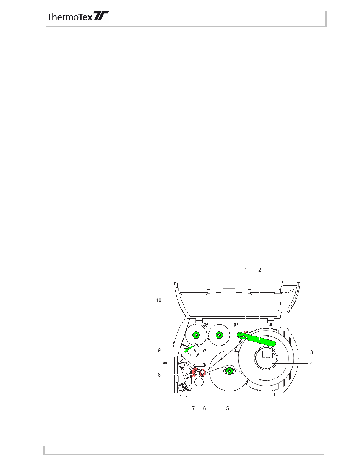
1.4 Parts of the printer
1 Retaining screw
2 Roll guide
3 Roll holder
4 Core adapter 76mm (option)
5 Internal winder (option)
6 Sliding guide ring
7 Label light barrier
8 Hex key
9 Lever for locking print head
10 Lid
Fig. 1-1 - Parts of the printer
Product description
GBTT4SBA
Page - 5
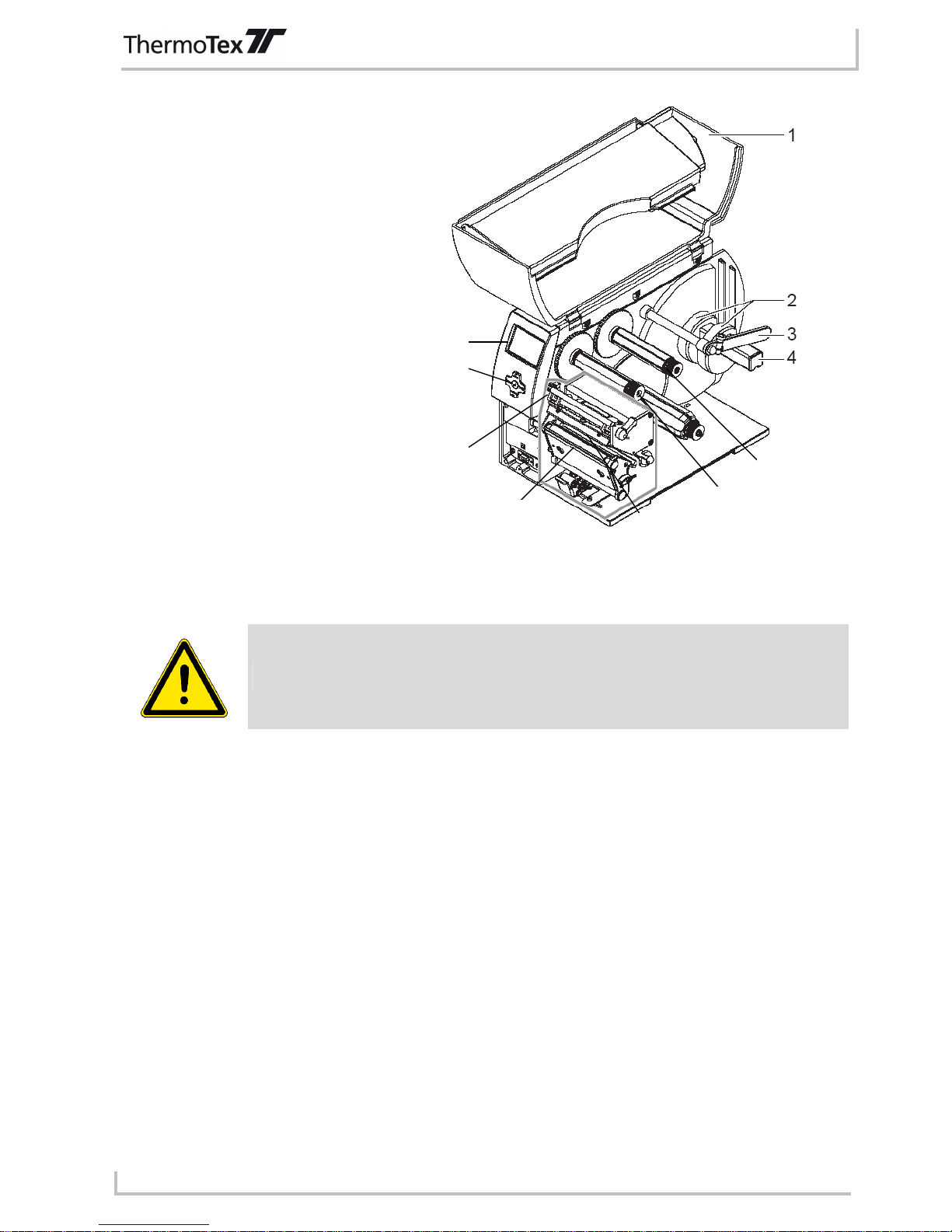
1 Lid
2 Core adapter 76mm (option)
3 Roll guide
4 Roll holder
5 Display
6 Navigator pad
7 Transfer film deflector
8 Printing roller
9 Print head
10 Film winder
11 Film unwinder
Fig. 1-2 - Parts of the printer
1.5 Properties of the thermo print head
The thermo print head is the most delicate part of your printer. Please always comply with
the following instructions.
1. Do not touch the glass safeguard on the print head with your hand. Do not use any sharp objects (knife,
screwdriver, etc.) to clean the print head.
2. During printing, make sure that there are no impurities on the label which could be pulled through under
the print head. These could damage the head.
3. Ensure the label has a good, smooth surface. Rough label surfaces act as sandpaper and reduce the
service life of the head.
4. Clean the head regularly with cotton buds soaked in alcohol.
5. Print at the lowest possible head temperature.
Incorrect handling can damage your print head very quickly.
1.6 Instructions for the lithium battery
The electronic board of your printer is equipped with a lithium battery. Discharged batteries must be disposed of
in corresponding old battery collections. If the batteries are not completely discharged, place adhesive tape over
the poles to prevent short circuits.
When decommissioning the printer, the battery must always be disposed of separately from the rest of the
printer.
5
6
7
8
9
10
11

Product description
GBTT4SBA
Page - 6
1.7 Declaration of conformity
CE Declaration of Conformity
Manufacturer:
ThermoTex Nagel GmbH
Schutterstraße 14
D-77746 Schutterwald
Device description:
Type: TT4-S
Production status: December 2009
The device fulfils the health and safety requirements of the following EC directives:
• Low voltage directive 2006/95/EC
Applied standard: EN 60950-1:2006
• Electromagnetic compatibility directive 2004/108/EC
Applied standards: EN 55022:2006
EN 55024:1998+A1:2001+A2:2003
EN 61000-3-2:2006
EN 61000-3-3:1995+A1:2001+A2:2005
Schutterwald, 17.12.2009
ThermoTex Nagel GmbH
Dietmar Nagel
(Managing Director)
Safety instructions
GBTT4SBA
Page - 7
2 Safety instructions
The following warning symbols are used on the machine and in this operating manual:
Hazard Warning
Warning, dangerous electrical voltage
Warning of cutting injuries
Disconnect from the power supply
Always comply with the following safety instructions to avoid personal injuries or damage to
the printer.
• The printer must only be operated by correspondingly trained and authorised staff who know the manual and
are capable of working accordingly,
• Only connect the unit to a power supply with suitable voltage. The unit is rated for AC voltage from 100 to
240 V. Only connect the printer to a grounded power socket.
• Only connect the printer to units with protective low voltage.
• Ensure that all units being connected (printer, computer etc.) are switched off when connecting together.
Also switch the units off before disconnecting them.
• Ensure that your printer is not exposed to damp or wet conditions.
• The printer can be operated with the lid opened. In this condition, the rotating parts are freely accessible.
Ensure that no hair, jewellery etc. can get caught up in these rotating parts.
• During operation, the print head component can get hot. Beware when touching the component.
• Disconnect the printer from the power supply before starting any cleaning or maintenance work.
• Only qualified maintenance technicians should repair the printer.
Do not open the rear wall! Mortal risk from power supply voltage!
Initial commisioning
GBTT4SBA
Page - 8
3 Initial commissioning
3.1 Power connection
The printer is equipped with a wide-range power unit (100...240V~) so that it can be operated from a power
supply of both 230V~/50Hz and 115V~/60Hz without having to interfere with the printer.
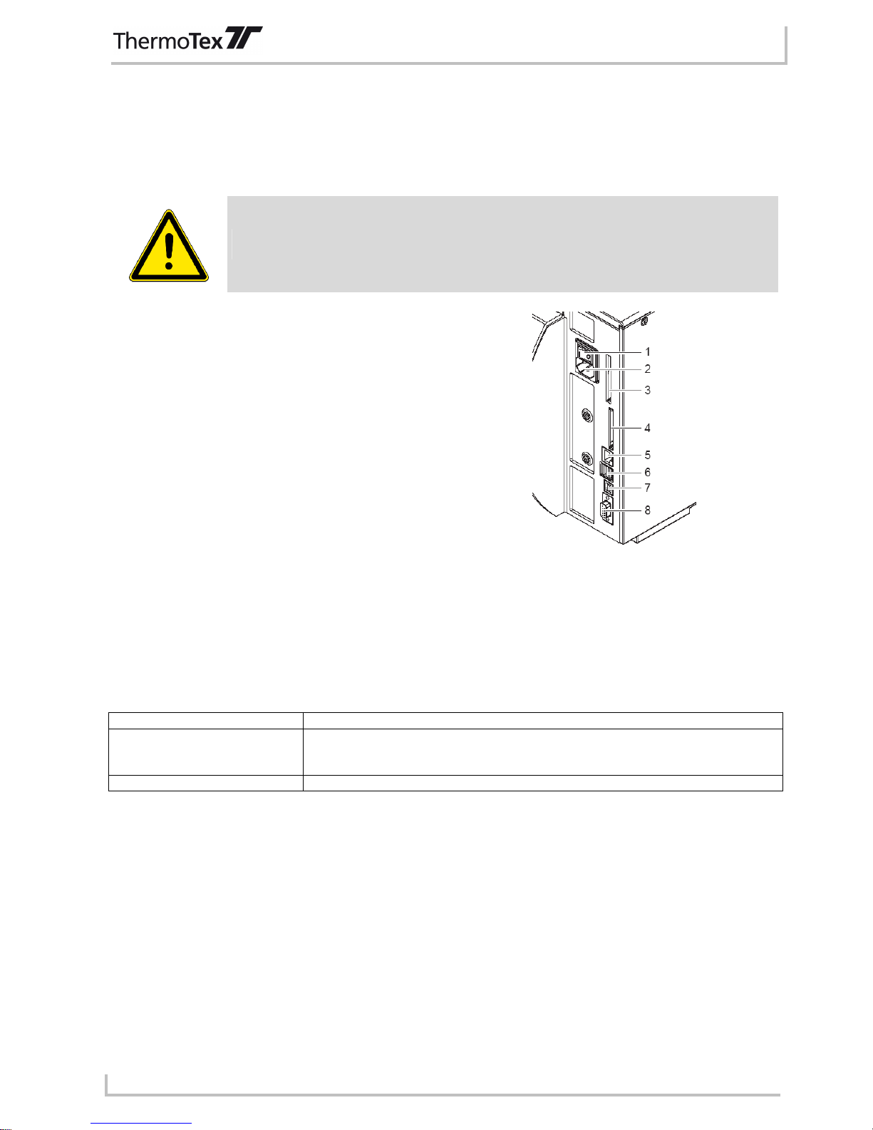
Before connecting your printer to the power supply, make sure that the power switch (1) is
in the "0" (OFF) setting.
1 Power switch
2 Power socket
3 Slot for card bus or PC card type II
4 Slot for CompactFlash memory card
5 Ethernet 10/100 Base-T
6 USB interface for keyboard and/or scanner
7 USB high-speed slave interface
8 Serial RS 232 C interface
Fig. 3-1 - Connecting the printer
Connect the power lead to the power socket (2) and plug the lead into an earthed socket.
3.2 Connecting to the computer
The standard printer has a serial RS-232 interface (8), a USB high-speed interface (7) and an Ethernet 10/100
Base-T interface (5). For a serial connection, the RS-232 interface of the printer must be configured according to
the settings on your computer.
Standard settings on delivery:
Interface Configuration
RS-232 Baud rate: 115200
Parity: none
Flow control: RTS/CTS
Data bits: 8
Stop bits: 1
Ethernet 10/100 Base-T DHCP: on Gateway: off
Connect the computer and printer with a suitable lead and use the screws or straps on the connectors to secure
the lead connection.
3.3 General information for inserting labels and ink ribbons
The various control and adjusting elements inside the printer are marked green or red.
Only the green control elements are required to change a label roll or ink ribbon roll of the same width.
It may be necessary to use the red control elements as well when inserting a label roll or ink ribbon roll of a
different width.
Initial commisioning
GBTT4SBA
Page - 9
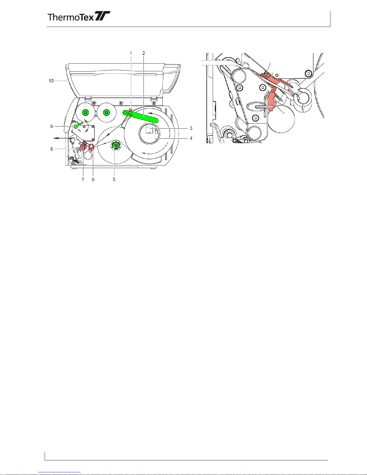
3.4 Inserting labels
Fig. 3-2 - Inserting labels Fig. 3-3 - Adjusting the label light barrier
1. Loosen the knurled screw (1), swivel the guide (2) upwards and push it as far as possible to the outside.
2. Place the roll of labels on the roll holder (3) and unwind a longer strip of labels from the main roll. Push the
roll as far as it will go.
3. Swivel the guide (2) down to the roll holder (3). Push the guide against the main roll so that it is braked
slightly when unwinding. Tighten the knurled screw (3).
4. Swivel the lever (9) counter-clockwise as far as it will go, thus lifting the print head component.
5. Push the guide ring (6) outwards as far as it will go.
6. Guide the strip of labels through the printer as shown in Fig. 3-2. The run of paper for labels on the outside
is shown as a continuous line, the run of paper for labels on the inside as a dotted line.
ThermoTex rolls of labels are on the outside, i.e. the side being printed is on the outside. Exception:
ThermoTex fix plastic film: this is on the inside.
7. Adjust the label light barrier (12) so that the actual sensor (11) can register the gap between the labels or
the reflection or perforation marks. To adjust, push the label light barrier into the right position using the
handle (13).
8. Push the guide ring (6) against the outer edge of the strip of labels.
9. Swivel the lever (9) clockwise as far it will go. This locks the print head.
3.4.1 Adjusting the print head pressure
The print head is pressed in position by two tappets. The outer sliding tappet must be adjusted to the width of the
textile tape being used. The sliding tappet must be positioned to produce uniform printing quality. The tappets
can be adjusted to prevent any pleating.
11
12
13
 Loading...