

ThermoTex Thermo-Ident 1, Thermo-Ident 2 Operating Manual
ThermoTex Nagel GmbH
Schutterstr. 14, 77746 Schutterwald, GERMANY
Phone +49 781 9616-0, fax +49 781 9616-50
info@thermo-tex.de, www.thermo-tex.de
GBTHIDBA_V(2).DOC
Operating manual for
Thermo-Ident 1 and
Thermo-Ident 2
- Translated version of the original operating manual -

Contents
GBTHIDBA_V(2).DOC Page - 2
Contents
1! Product description .......................................................................................................... 3!
1.1! General description and intended use ......................................................................................................... 3!
1.2! Machine versions ......................................................................................................................................... 4!
1.3! Layout .......................................................................................................................................................... 4!
1.4! Technical data ............................................................................................................................................. 4!
1.5! Declaration of Conformity ............................................................................................................................ 5!
2! Safety advice ..................................................................................................................... 5!
2.1! Warning symbols ......................................................................................................................................... 5!
2.2! Dangerous spots on the machine ................................................................................................................ 6!
2.3! Safety devices ............................................................................................................................................. 6!
2.4! Due diligence by the operator ...................................................................................................................... 6!
2.5! Basic safety measures in standard operation .............................................................................................. 6!
2.6! Basic safety measures for maintenance and servicing ............................................................................... 7!
3! General advice .................................................................................................................. 8!
3.1! Transport ..................................................................................................................................................... 8!
3.2! Unpacking the machine ............................................................................................................................... 8!
3.3! Installation advice ........................................................................................................................................ 8!
3.4! Start-up ........................................................................................................................................................ 8!
3.5! Properties of the thermal print head ............................................................................................................ 9!
3.6! Materials and parameters .......................................................................................................................... 10!
4! General operation ........................................................................................................... 11!
4.1! Principal work sequence ............................................................................................................................ 11!
4.2! Inserting the ink ribbon roll ........................................................................................................................ 11!
4.3! Inserting the marking tape ......................................................................................................................... 11!
4.4! Changing between temporary and permanent marking ............................................................................ 12!
5! Operation of the control unit .......................................................................................... 13!
5.1! Operating display ....................................................................................................................................... 13!
5.2! Menus ........................................................................................................................................................ 14!
5.3! Quick access buttons ................................................................................................................................ 15!
5.4! Operating modes ....................................................................................................................................... 15!
5.5! Entering text .............................................................................................................................................. 15!
5.6! Saving the settings .................................................................................................................................... 16!
6! Description of menu points ............................................................................................ 17!
6.1! Numbering ................................................................................................................................................. 17!
6.2! Automatic printing ...................................................................................................................................... 17!
6.3! Delete text after print ................................................................................................................................. 17!
6.4! Logo print ................................................................................................................................................... 17!
6.5! Label type .................................................................................................................................................. 18!
6.6! Barcode type ............................................................................................................................................. 18!
6.7! Check digit ................................................................................................................................................. 18!
6.8! Label alignment ......................................................................................................................................... 18!
6.9! Print position .............................................................................................................................................. 18!
6.10! Label length ........................................................................................................................................... 18!
6.11! Single label length .................................................................................................................................. 18!
6.12! Double label length ................................................................................................................................ 18!
6.13! Immediate heat-seal .............................................................................................................................. 18!
6.14! Font size ................................................................................................................................................ 19!
6.15! Heat-seal temperature for temporary marking ....................................................................................... 19!
6.16! Heat-seal temperature of the permanent marking ................................................................................. 19!
6.17! Heat-seal temperature for the "heat-seal removal" operating mode ...................................................... 19!
6.18! Short temporary marking heat-seal time ................................................................................................ 19!
6.19! Long temporary marking heat-seal time ................................................................................................ 19!
6.20! Permanent marking heat-seal time ........................................................................................................ 19!
6.21! Operating mode ..................................................................................................................................... 19!
6.22! Baud rate ............................................................................................................................................... 19!
6.23! Language ............................................................................................................................................... 19!
Contents
GBTHIDBA_V(2).DOC Page - 3
6.24! Keyboard allocation ............................................................................................................................... 20!
6.25! Daily counter .......................................................................................................................................... 20!
6.26! Total counter .......................................................................................................................................... 20!
6.27! Operating hours counter ........................................................................................................................ 20!
6.28! Heating energy ....................................................................................................................................... 20!
6.29! Copy logos ............................................................................................................................................. 20!
6.30! Gluing Teflon .......................................................................................................................................... 21!
6.31! Heat-seal removal .................................................................................................................................. 21!
7! Label layout ..................................................................................................................... 22!
7.1! Examples for Thermo-Ident 1 .................................................................................................................... 22!
7.2! Examples for Thermo-Ident 2 .................................................................................................................... 23!
8! Remote control ................................................................................................................ 24!
8.1! Serial interface ........................................................................................................................................... 24!
8.2! Ethernet connection ................................................................................................................................... 24!
8.3! Communication sequence ......................................................................................................................... 24!
8.4! PC data transfer → Thermo-Ident ............................................................................................................. 25!
8.5! Data transfer Thermo-Ident → PC ............................................................................................................. 25!
9! Error Messages ............................................................................................................... 26!
10! Assistance with faults ................................................................................................. 27!
11! Servicing (maintenance) .............................................................................................. 28!
11.1! Basic safety measures for maintenance and servicing .......................................................................... 28!
11.2! Cleaning the print head .......................................................................................................................... 28!
11.3! Teflon film .............................................................................................................................................. 28!
11.4! Heat-seal rubber .................................................................................................................................... 28!
11.5! Air filter ................................................................................................................................................... 29!
11.6! Maintenance message ........................................................................................................................... 29!
12! List of spare parts ........................................................................................................ 29!
13! Circuit diagram ............................................................................................................. 30!
This document is the translated version of the original German
operating manual. For any translations into other languages, the
original German manual must be used as a basis. You can obtain the
original manual from ThermoTex.
1 Product description
1.1 General description and intended use
The Thermo-Ident marking machine may exclusively be used for temporary or permanent textile marking. The
machine prints labels, cuts them off and applies them to textiles.
Depending on the type of marking tape and the set parameters, temporary marking or permanent marking is
possible.
The labels are resistant to most industrial washing and dry-cleaning processes. Temporary labels can be
removed from the textile without residues after the washing or dry-cleaning process.
Safe operation of the machine is not guarantee if the marking machine is not used
for this purpose.
The following improper uses are to be excluded:
• Do not leave any highly flammable objects or any processing materials in or on the
machine; do not use any highly flammable objects and no flammable liquids and do not
Product description
GBTHIDBA_V(2).DOC Page - 4
use them or place them near the machine. This also applies to liquids or solids that can
disintegrate thermally into dangerous substances.
• Do not use the machine to dry or remove stains, especially with flammable liquids.
Observation of all information in the manual is part of proper use.
1.2 Machine versions
1.2.1 Thermo-Ident 1
The width of the marking tape is 10 mm.
Single line and double line labels can be printed.
1.2.2 Thermo-Ident 2
The width of the marking tape is 15 mm.
Labels with up to four lines can be printed.
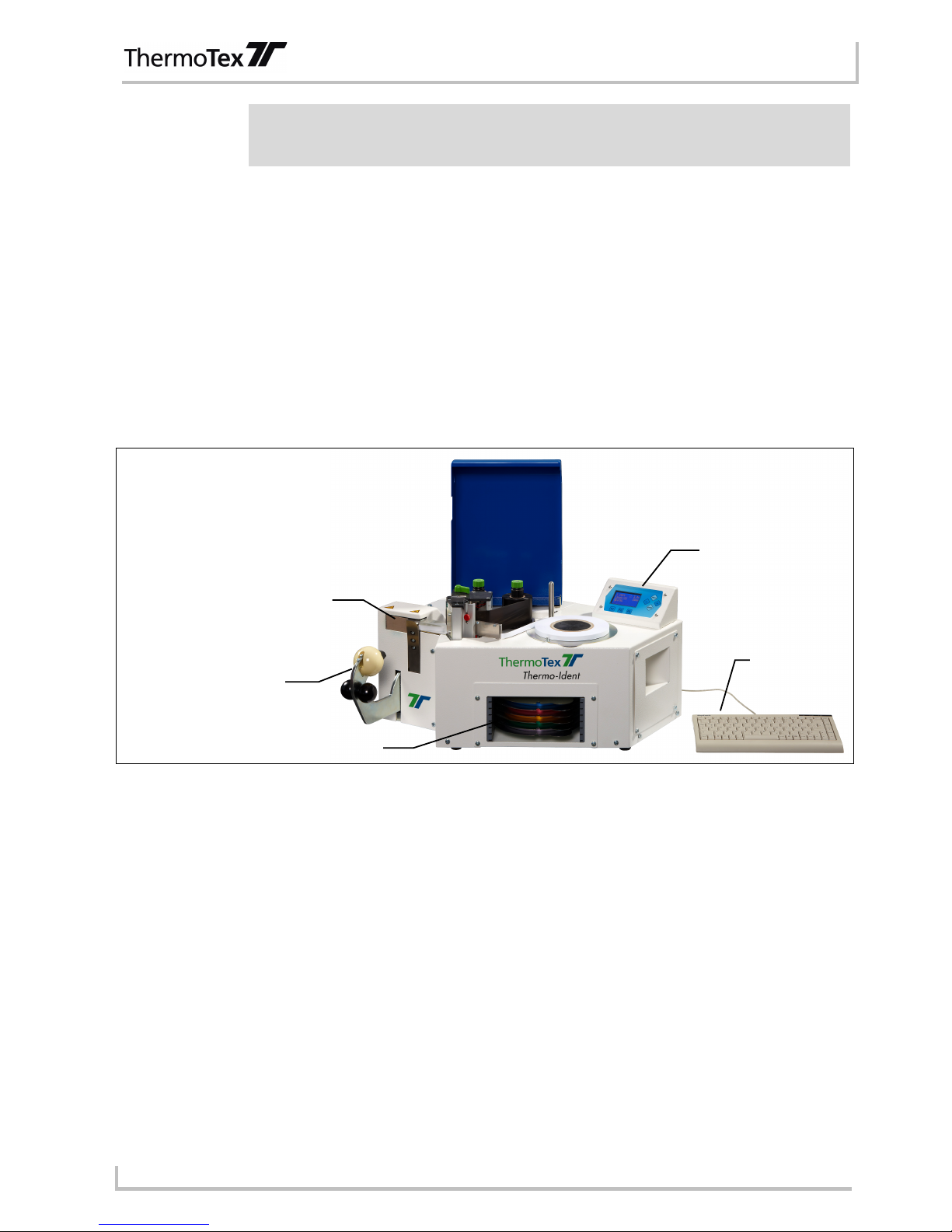
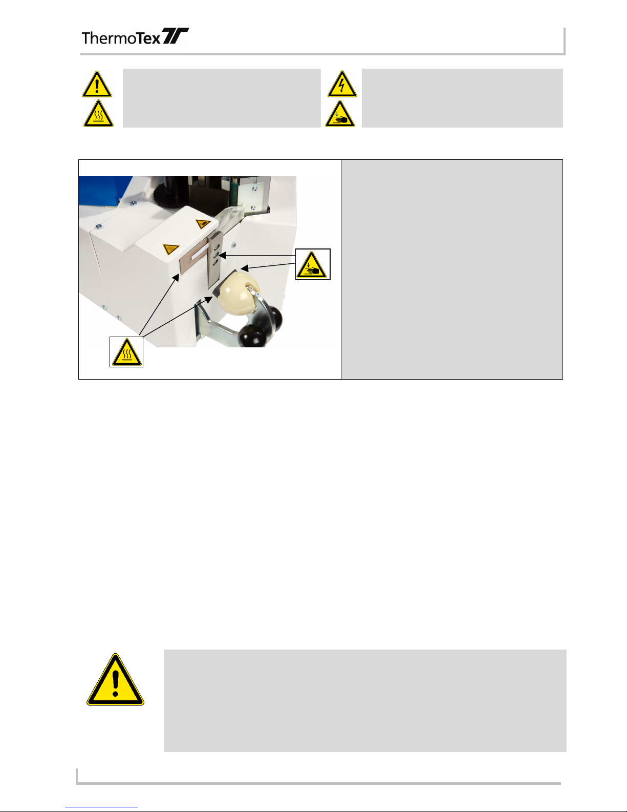
1.3 Layout
Figure 1-1
1.4 Technical data
Type name: Thermo-Ident 1 / Thermo-Ident 2
Electrical connection values: 230 V, 50 Hz, 500 W
Nominal current: 2.2 A
Fuse: 4.0 A (time-lag)
Noise emissions: Workplace-related emission value < 70 dB (A)
Keyboard: Mini keyboard with USB connection
Serial interface: 9-pole Sub-D plug (connection to a PC using a null modem cable)
Network interface: RJ45 socket
Compressed air connection: 4 bar working pressure, maximum authorised pressure 6 bar
Dimensions:
Width: 540 mm
Height: 310 mm
Depth: 460 mm
Weight: 32 kg
Hand lever with
heat-seal rubber
Heating element
with Teflon film
Control unit
Roll holder
Keyboard
Declaration of conformity
GBTHIDBA_V(2).DOC Page - 5
1.5 Declaration of Conformity
"CE" Declaration of Conformity
Manufacturer:
ThermoTex Nagel GmbH
Schutterstraße 14
77746 Schutterwald
Device description:
Type: Marking machine Thermo-Ident 1 / Thermo-Ident 2
Production status: April 2012
The device fulfils the health and safety requirements of the following EC directives:
• Machinery directive 2006/42/EC
Applied standards: EN 13857:2008
EN 13732-1:2008
EN ISO 12100:2010
EN 60204-1:2006/A1:2009
• Electromagnetic compatibility directive 2004/108/EC
Applied standards: EN 61000-6-2:2005
EN 61000-6-3:2007
Schutterwald, 24.04.2012
ThermoTex Nagel GmbH
Dietmar Nagel
(Managing Director)
2 Safety advice
2.1 Warning symbols
The following warning symbols are found on the machine and in this manual:
Safety advice
GBTHIDBA_V(2).DOC Page - 6
"Warning of dangerous spots"
"Warning of dangerous electrical voltages".
"Warning of hot surfaces"
"Warning of hand injuries"
2.2 Dangerous spots on the machine
Caution, hot surfaces!
• The heating element can reach temperatures
above 200°C.
• The heat-seal rubber on the hand lever can
become hot.
• The processed material can become hot.
Caution, risk of hand injuries!
• There is the risk of cuts and crushing in the
area of the cutting device.
• There is the risk of crushing in the area of the
hand lever. Do not reach into the space
between the hand lever and heating element!
2.3 Safety devices
The machine is protected with a 4.0 A (time-lag) microfuse.
The heating element is protected with a thermal fuse.
2.4 Due diligence by the operator
The operator must particularly ensure the following:
• The machine is only used for the intended purpose
• No unauthorised conversions and changes are made to the machine
• The machine is only operated in a perfect, fully functional condition and that the safety equipment is
particularly checked regularly for functionality
• The full operating manual is always kept in a legible condition at the place of use of the machine
• Only sufficiently qualified and authorised personnel operate, maintain and repair the machine
• These members of personnel are regularly inducted in all relevant issues of work safety and environmental
protection and are aware of the manual and especially the safety advice contained in it
• All safety and warning device personally attached to the machine may not be removed and must remain
legible.
2.5 Basic safety measures in standard operation
• The machine may only be operated by trained and authorised persons who are aware of
the manual and can work following the manual!
• Check and make sure that only authorised persons are within the working range of the
machine when switching the machine on.
• Check the machine for any visible damages before beginning production and ensure
that it is only operated in perfect condition! Report any defects immediately to the
superior!
• Check and make sure that all safety devices are in perfect working order before
Safety advice
GBTHIDBA_V(2).DOC Page - 7
beginning production!
• The materials to be processed must be checked with respect to possible risks before
processing (temperature resistance, gases or toxicity).
• The Teflon film on the heating plate must be immediately replaced if damaged.
• The machine must always be switched off after finishing work (mains switch).
2.6 Basic safety measures for maintenance and servicing
• Comply with the specified inspection and maintenance intervals in the manual!
• Switch the machine off before beginning maintenance and repair work, disconnect the
power connector and release the air connection!
• Before carrying out maintenance and repair work, make sure that any parts of the
machine that it is possible to touch have cooled down to room temperature!
• Repair work on the electrical equipment on the machine may only be carried out by
trained electricians!

General advice
GBTHIDBA_V(2).DOC Page - 8
3 General advice
3.1 Transport
Before transport, make sure that any parts of the machine that it is possible to touch have cooled down to room
temperature! The mains cable, compressed air hose and data cable to the PC system must be removed for
transport.
3.2 Unpacking the machine
When unpacking the marking machine, make sure that all of the parts listed as follows are definitely included in
the delivery and are not damaged:
• Thermo-Ident 1 or Thermo-Ident 2 marking machine
• Compressed air hose
• Keyboard
• Power cable
• Manual
• 1 set of tape rests
3.3 Installation advice
Please give some thought to where the machine should be installed before taking the machine into operation.
• The machine must be positioned on a strong and level base.
• A specific table height does not need to be maintained. It should however be chosen to suit the person
working on the machine.
• The mains socket must be close to the machine and easy to access.
• Make sure that no highly flammable objects are near to the heating plate.
• Installation in rooms at risk of explosion is prohibited.
• The machine may only be used in dry indoor areas.
• The air filter is equipped with an automatic water separator. This empties itself automatically if required so
that the installation area under the machine can be checked for moisture at regular intervals.
3.4 Start-up
• The machine must be switched off when connecting the connection cables.
• Insert the ink ribbon roll (see chapter 4.2).
• Connect the keyboard to the USB socket on the right side of the machine.
• The compressed air is connected using a euro coupling on the back of the machine.
• The connection cable to a computer system (9-pole Sub-D plug) can be connected on the serial interface.
• You can connect the machine to a network with the RJ45 socket.
• Insert the supplied power cable into the back of the machine. Insert the power cable plug into a protective
contact socket.
The voltages stated on the type label must match the mains voltages in the place of
installation.
• Switch the machine on with the main switch on the back.
• Insert a marking tape (see chapter 4.3).
General advice
GBTHIDBA_V(2).DOC Page - 9
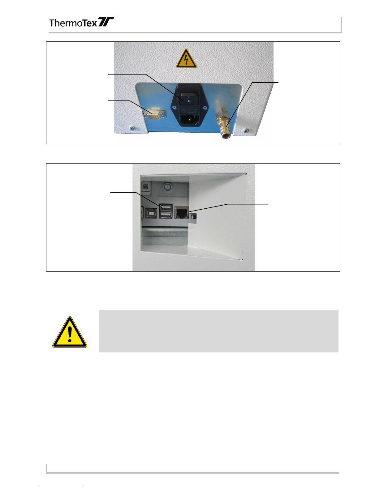
Figure 3-1
Figure 3-2
3.5 Properties of the thermal print head
The thermal print head is the most sensitive part of your machine. It is compulsory to pay
attention to the following advice.
• The glass protection layer on the print head may not be touched by hand. Never use any sharp objects
(knife, screwdriver or similar) to clean the print head.
• Make sure when printing that no dirt is on the labels that could be pulled through under the print head. This
could damage the print head.
• Pay attention to a good, smooth label surface. Rough label surfaces are like sandpaper and reduce the life
span of the print head.
• Clean the print head at regular intervals with a cotton bud soaked in alcohol.
• Print with the lowest possible heating energy.
Your print head can be damaged very quickly if handled incorrectly.
Power connector
and main switch
Serial interface
Compressed air
connection
USB connection
Ethernet connection
 Loading...