

Thermosystems TM91, TM95 Series, TM92 Series, TM96 Series Programming Manual
MANUALE di PROGRAMMAZIONE
TM91 - TM92*- TM95*- TM96*
TM91 - TM92*- TM95*- TM96*
Il display superiore indica normalmente il valore della variabile di ingresso.
Il display inferiore indica normalmente il valore del Set Point corrente e svolge
funzioni di display di servizio per le operazioni di impostazione ecc.
Con i tre tasti frontali e' possibile programmare in modo completo il regolatore.
Si puo' scegliere la scala, il tipo di sensore, il Set Point, il tipo di allarme, ecc...
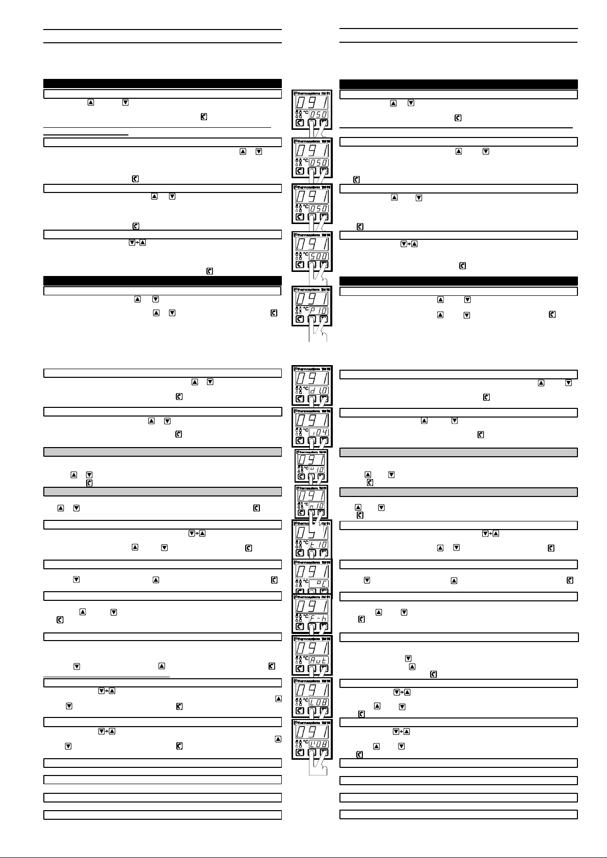
SET-POINT MAIN ( led " M " lampeggiante )
Agendo sul tasto o sul tasto si può impostare il valore desiderato.
Il lampeggio del led M evidenzia tale condizione operativa.
Per memorizzare il nuovo valore si deve infine premere il tasto . Il valore di default è 50°C.
Se per 4 sec. non si preme alcun tasto il display torna ad indicare il Set-Point
precedentemente impostato.
SET-POINT ALLARME I ( led " I " lampeggiante )
Quando ci si trova nella funzione SetPoint, premendo contemporaneamente e si
accede direttamente all' impostazione del Limit I.
Il lampeggio del led I evidenzia tale condizione operativa. Il valore di default previsto è 50°C.
Si puo' modificare il valore incrementando o decrementando con i due tasti appositi e
confermare in memoria con il tasto .
SET-POINT ALLARME II ( led " I I " lampeggiante )
Premendo di nuovo contemporaneamente e si accede direttamente all' impostazione
del Limit II.
Il lampeggio del led II evidenzia tale condizione operativa. Il valore di default previsto è 50°C.
Si puo' modificare il valore incrementando o decrementando con i due tasti appositi e
confermare in memoria con il tasto .
MAX SET-POINT ( leds " M " , " I " e " I I " lampeggianti )
Premendo nuovamente la coppia appare a display il valore massimo del Set-Point.
Questo valore può essere prefissato e rappresenta il limite massimo entro cui si può variare il
Set-Point e relative implicanze. Il valore di default è preimpostato a 500 °C .
Il lampeggio dei leds M, I, II evidenzia tale condizione operativa.
Ogni nuovo valore prescelto deve essere confermato con il tasto per venire memorizzato.
BANDA PROPORZIONALE Pxx
Premendo contemporaneamente e si passa in rassegna i parametri di
regolazione. Il primo di questi e' la BANDA PROPORZIONALE.
E' possibile modificarne il valore tramite o e confermare poi in memoria con .
Il campo di variazione va da 0 a 99%. Il valore di default è fissato al 10%.
Il calcolo viene eseguito sul campo scala totale (es. Pt100 -199/+500 -->699).
Se la Banda Proporzionale viene posta a zero (0), il regolatore interviene in modo
ON-OFF, ossia si comporta da termostato.In questo caso i parametri che
seguono rappresentano gli intervalli di isteresi superiore ed inferiore.
Con Banda Proporzionale diversa da zero il regolatore interviene nel modo PID
ed i parametri successivi rappresentano i tempi di azione derivativa ed integrale.
TEMPO DERIVATIVO dx.x
Dopo aver visualizzato la Banda Proporzionale, premendo e compare il valore del
tempo di azione derivativa espresso in minuti. NB. accessibile solo se P.B. # 0.
Si può modificare e poi confermare in memoria con . Il valore di default è pari a 1 min.
Il campo di variazione va da 0 a 9.9 min (se 0 azione derivativa esclusa).
TEMPO INTEGRALE ixx
Premendo ancora contemporaneamente e compare il valore del tempo integrale
espresso in minuti. NB. accessibile solo se P.B. # 0.
Si può modificare e poi confermare in memoria con . Il valore di default è pari a 4 min.
Il campo di variazione va da 0 a 20 min (se 0 azione integrale esclusa).
ISTERESI SUPERIORE
Dopo la visualizzazione della Banda Proporzionale nulla, compare il valore in gradi
dell' intervallo di isteresi superiore, cioè situato sopra il Set Point.
Con i tasti e si può impostare un valore compreso tra 0 e 99 °punti.
Premere il tasto per confermare il nuovo valore. NB. accessibile solo se P.B. = 0.
ISTERESI INFERIORE nxx
L' intervallo di isteresi inferiore va inteso al di sotto del Set Point.
Con e si può impostare un valore tra 0 e 99 punti e confermare con il tasto per
memorizzare il nuovo valore. NB. accessibile solo se P.B. = 0.
TEMPO DI CICLO txx
Dopo il tempo integrale, premendo contemporaneamente , compare il tempo di ciclo
dell' uscita (relè oppure statica). NB. accessibile solo se P.B. # 0.
Si puo' modificare il valore tramite oppure e confermare poi con il tasto .
Il campo di variazione va da 1 a 99 sec. Il valore di default è pari a 10 sec.
SCELTA °C / °F °C / °F
Il parametro successivo permette la scelta delle unità di misura °C o °F
Con il tasto si seleziona °C e con il tasto si seleziona °F e confermare poi con il tasto .
La relazione che lega le due unità di misura è °F=(°Cx9/5)+32 . Il valore di default è °C.
FUNZIONE RISCALDAMENTO / RAFFREDDAMENTO F-h / F-C
Il parametro seguente è la funzione RISC. / RAFF.
Tramite i tasti oppure si può selezionare la funzione desiderata e confermare con il
tasto per memorizzare. Il valore di default corrisponde a F-h .
Ci sono 2 possibilità : F-h = RISCALDAMENTO (hot) e F-C = RAFFREDDAMENTO (cool)
SCELTA AUTOMATICO / MANUALE Aut / MAn
Il parametro che segue permette la selezione fra le funzioni AUTOMATICO e MANUALE. La
prima permette al regolatore di operare normalmente mentre con la seconda è possibile
forzare la potenza in uscita (in percentuale).
Con il tasto si seleziona Aut e con il tasto si seleziona MAn ; confermare poi con .
Si consiglia di operare in funzione AUTOMATICO . Il valore di default corrisponde a Aut .
TIPO DI ALLARME I L0x
Premendo i due tasti appare a display il tipo di allarme I prescelto.
Sono previsti nove (9) tipi di allarme e dunque si può predisporre un valore da 0 a 8 tramite
oppure e memorizzare poi la scelta con il tasto .
Default = L08 (vedere grafico funzioni allarmi sottoriportato) .
TIPO DI ALLARME II L'0x
Premendo i due tasti appare a display il tipo di allarme prescelto II.
Sono previsti nove (9) tipi di allarme e dunque si può predisporre un valore da 0 a 8 tramite
oppure e memorizzare poi la scelta con il tasto .
Default = L'08 (vedere grafico funzioni allarmi sottoriportato) .
SET- POINT MAIN ( led " M " lampeggiante )
Vedere " IMPOSTAZIONI SET - POINT (SET-POINT MAIN)" .
SET-POINT ALLARME I ( led " I " lampeggiante )
Vedere " IMPOSTAZIONI SET - POINT (SET-POINT ALLARME I)" .
SET-POINT ALLARME II ( led " I I " lampeggiante )
Vedere " IMPOSTAZIONI SET - POINT (SET-POINT ALLARME II)" .
MAX SET-POINT ( leds " M " , " I " e " I I " lampeggianti )
Vedere " IMPOSTAZIONI SET - POINT (MAX SET-POINT)" .
CONFIGURAZIONE PARAMETRI REGOLAZIONE
CONFIGURAZIONE PARAMETRI REGOLAZIONE
RAMETRI REGOLAZIONE
IMPOSTAZIONI SET - POINT
u
xx
PROGRAMMING MANUAL
Upper display shows input variable value .
Lower display normally shows current Set Point and service informations during
functions setting etc.
It is possible to program the controller with three keys.
One can select the range, the input sensor, Set Point, alarm type etc. ...
SET-POINT MAIN ( led " M " flashing )
Pushing either the or key is possible to change the Set Point.
The led M (which normally indicates the relay output action) flashes.
To hold in memory the new value the key must be pushed. Default value is 50°C.
If for 4 sec. no key is pushed the display will indicate the previous Set Point.
SET-POINT ALARM I ( led " I " flashing )
If, during displaying of the Set Point, keys and are pushed at the same time,
then a direct access to the Limit I value is obtained.
The led I (which normally indicates the relay output action) flashes.
It can be modified incrementing or decrementing its value and confirm into memory by
the key. Default value is 50°C.
SET-POINT ALARM II ( led " I I " flashing )
Again, by pushing and keys at the same time a direct access to the Limit II
value is obtained.
The led II (which normally indicates the relay output action) flashes.
It can be modified incrementing or decrementing its value and confirm into memory by
the key. Default value is 50°C.
MAX SET-POINT ( leds " M " , " I " e " I I " flashing )
By pushing the key pair the maximum allowed value of the Set Point appears on the
display.This value can be set and represent the maximum value at which the Set Point can be
set. Default value is preimposed at 500 °C .
The value choosen must be confirmed by the key in order to hold it in a permanent
way.
PROPORTIONAL BAND Pxx
Pushing at the same time the keys and one can rewiew the control actions
settings. The first one is the PROPORTIONAL BAND.
It is possible to change its value by and keys and then confirm by .
Settings range goes from 0 to 99%. Default value is 10%.
Global range is considered for evaluate actions (ie. Pt100 -199/+500 -->699).
If the Proportional Band is set to zero the controller change its working mode
to ON-OFF that is it works as a thermostat. In this case the following
parameters represent the hysteresis interval over and under the set point.
With a Proportional Band different from zero, the controller works as a PID
and the successive parameters represent derivative and integral action time.
DERIVATIVE TIME dx.x
After having showed the Proportional Band and by pushing together the and
keys the value of derivative time action expressed in minutes appears.
One can change and then confirm in memory by the key. Default value is 1 min.
The variation field goes from 0 to 9.9 min (if 0 derivative action is off).N.B.av.if PB #0 .
INTEGRAL TIME ixx
By pushing at the same time and the value of integral time action is shown,
expressed in minutes. N.B. available if P.B.# 0 .
It is possible to change its value and to confirm by key. Default value is 4 min.
The range goes from 0 to 20 min (if 0 integral action is off).
SUPERIOR HYSTERESIS
After the visualisation of the Proportional Band at zero, the value of hysteresis interval
over the set point is shown. N.B. available if P.B.= 0 .
With the and keys one can set a value between 0 and 99 °C.
The key pushing confirm into memory the new value.
INFERIOR HYSTERESIS nxx
The interval of the inferior hysteresis is to be intended as under the Set Point.
With and a new value can be set from 0 to 99 °C. N.B. available if P.B.= 0 .
The load into memory the new value.
CYCLE TIME txx
After the integral time by pushing at the same time the cycle time of the
output (relay or static) appears. N.B. available if P.B.# 0 .
One can change the value through or and then confirme it with the key.
The field of variation goes from 1 to 99 sec. Default value is 10 sec.
°C / °F SELECTION °C / °F
The parameter following on the cycle time is measure unit selection .
Through the selection is °C and with keys one can select °F and confirm by .
Relationship by measurement units is °F=(°Cx9/5)+32. Default selected value is °C.
HEATING / COOLING ACTION F-h / F-C
The function following on the °C/°F selection is HEATING / COOLING.
Through the and keys one can select the preferred function and confirm by the
key. Default value is F - h .
There are two possible selections: F-h = HEATING and F-C = COOLING
AUTOMATIC / MANUAL SELECTION Aut / MAn
The parameter following on the heating/cooling action is the AUTOMATIC / MANUAL
selection .
Aut will be selected by key and is the normal operative condition .
MAn will be selected by key and should be used only when one must force output
Selection must be confirmed by key . Default value is Aut .
ALARM TYPE I L0x
By pushing the two keys the type of alarm I appears on the display (see alarm
function table). Nine (9) types of alarms are available and so value from 0 to 8 can be
set through and keys.
The key loads into memory the new choice. L08 is default value .
ALARM TYPE II L'0x
By pushing the two keys the type of alarm II appears on the display (see alarm
function table). Nine (9) types of alarms are available and so value from 0 to 8 can be
set through and keys.
The key loads into memory the new choice. L'08 is default value.
SET- POINT MAIN ( led " M " flashing )
You should see "SET - POINT SETTINGS" (SET-POINT MAIN).
SET-POINT ALARM I ( led " I " flashing )
You should see "SET - POINT SETTINGS" (SET-POINT ALARM I).
SET-POINT ALARM II ( led " I I " flashing )
You should see "SET - POINT SETTINGS" (SET-POINT ALARM II).
MAX SET-POINT ( leds " M " , " I " e " I I " flashing )
You should see "SET - POINT SETTINGS" (MAX SET-POINT).
SET - POINT SETTINGS
CONTROL PARAMETERS SETTINGS
u
xx
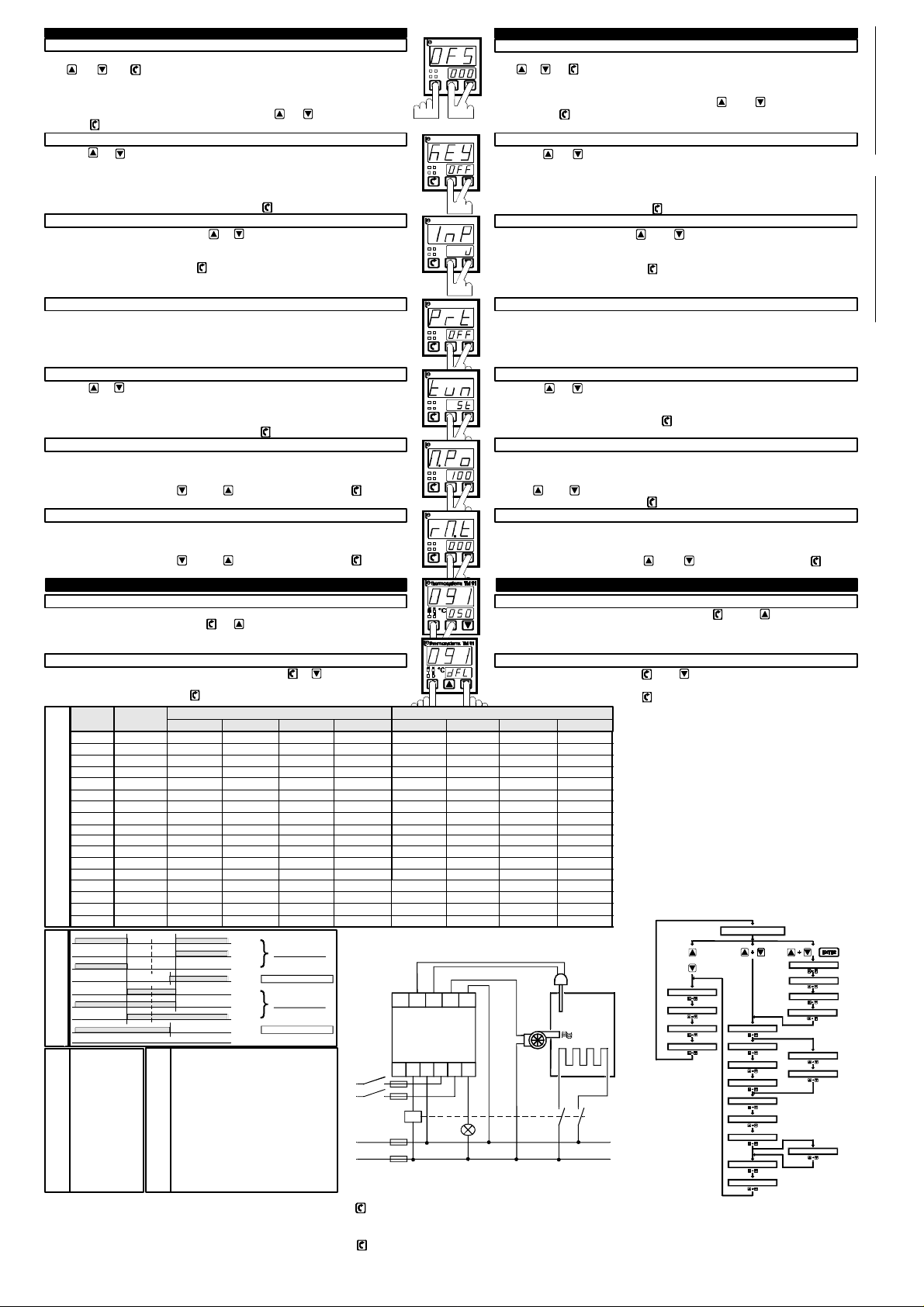
OFFSET OFS ---> X.X.X.
S E T P O I N T
CONFIGURAZIONE INGRESSI E SCALE
L' accesso alla configurazione dello strumento avviene premendo contemporaneamente i tre
tasti + + .
La conferma dell'accesso a questo tipo di parametri viene indicata dall'indicazione OFS sul
display superiore.
Il primo parametro è l' OFFSET, regolabile da -99 a +99 punti.
Come per gli altri parametri dopo la modifica del valore con e si deve confermare
con il tasto la memorizzazione del nuovo valore. Il valore di default è 000.
CHIAVE KEY ---> xxx
Premendo e si accede (dopo l'Offset) alla programmazione della chiave che può
avere tre stati :
OFF = chiave disabilitata -----> permesse tutte impostazioni .
Lo = chiave minima abilitata -----> ammesse impostazioni SetPoint M,I,II.
Hi = chiave massima abilitata -----> bloccate tutte le impostazioni .
Il livello di chiave prescelto deve essere confermato con . Il valore di default è OFF.
SCALE e INGRESSI InP ---> xx
Con la pressione contemporanea dei tasti e si accede alla programmazione delle
scale e relativi ingressi.
Per i dettagli e limiti relativi fare riferimento alla tabella INGRESSI e SCALE riportata avanti.
La scelta deve essere confermata con . Il il valore di default è " J ".
Nel caso di ingressi diversi da termocoppie e/o termoresistenze (es. 50mV, 1V, 10V ,0-20mA,
4-20mA, ... ) fare riferimento alle note integrative.
COMUNICAZIONE SERIALE Prt ---> OFF
Il parametro che segue riguarda la comunicazione seriale.
Questa funzione in questo manuale non è documentata ed interessa strumenti
espressamente realizzati con tale opzione.
Fare riferimento al manuale di comunicazione seriale per approfondimenti.
Si raccomanda di mantenere OFF (default) questa impostazione.
AUTO / SELF TUNING tun ---> xt
Premendo e si accede (dopo Comunicazione Seriale) alla programmazione del tipo di
regolazione automatica desiderata.
At= Auto-Tuning (ricerca parametri di regolazione ottimali sempre attiva).
St= Self-Tuning (ricerca parametri regolazione ottimali all'avvio processo).
Il livello di tuning prescelto deve essere confermato con . Il valore di default è "St".
MASSIMA POTENZA (ECONOMY) M.Po --- > xxx
Il parametro che segue permette di limitare la massima potenza erogabile dal sitema
controllato dallo strumento. Tale possibilità si rivela preziosa in caso di sistemi
sovradimensionati ed in molte applicazioni di risparmio energetico.
Si puo' modificare il valore tramite oppure e confermare poi con il tasto .
Il campo di variazione va da 0 a 100% . Il valore di default è pari a 100% .
RAMPA TIMER (SOFT-START) rM.t ---> 0xx
Questo parametro permette l'erogazione graduale della potenza all'accensione dello
strumento, seguendo una rampa che parte da 0% e raggiunge il valore calcolato
dall'apparecchio nel tempo impostato.
Si puo' modificare il valore tramite oppure e confermare poi con il tasto .
Il campo di variazione va da 0 a 99 min . Il valore di default è 0 min (rampa esclusa) .
TUNING - ON
La funzione di autoaggiustamento dei parametri di regolazione (Banda Prop., tempo integrale,
tempo derivativo) viene attivata con i tasti + .
Nel caso di Self-Tuning entra in azione solo se la temperatura è inferiore al Set Point ed il
regolatore si trova nella fase di riscaldamento del sistema.
CARICAMENTO PARAMETRI DI DEFAULT
Il caricamento dei parametri di default avviene premendo i tasti e contemporaneamente
e mantenendoli premuti fino al comparire della scritta " dFL " sul display inferiore (circa 4 sec).
La volontà va confermata con il tasto .
CODE INPUT TM91 - TM92 TM95 - TM96
IN SENSOR min. °C MAX °C min. °F MAX °F min. °C MAX °C min. °F MAX °F
P Pt100 -199 500 -199 932 -199 500 -328 932
P. Pt100 -19.9 99.9 --- --- -199.9 400.0 199.9 752.0
J Tc J 0 900 0 999 0 900 0 1.652
J. Tc J --- --- --- --- 0 400.0 --- -- K Tc K 0 999 0 999 0 1.300 0 2.372
K. Tc K --- --- --- --- 0 400.0 --- -- L Tc L 0 900 0 999 0 900 0 1.652
L. Tc L --- --- --- --- 0 400.0 --- -- n Tc N 0 999 0 999 0 1.300 0 2.372
n. Tc N --- --- --- --- 0 400.0 --- -- t Tc T 0 400 0 752 0 400 0 752
t. Tc T --- --- --- --- 0 400.0 --- -- r Tc R 0 999 0 999 0 1.760 0 3.200
S Tc S 0 999 0 999 0 1.760 0 3.200
b Tc B 0 999 0 999 0 1.810 0 3.290
INGRESSI e SCALE - INPUTS and RANGES
Lin. mV -mA /// /// /// /// /// /// /// ///
0 0
D IR E C T
0 1
0 2
A B S O L U T E
0 3
0 4
R E V E R S E
0 5
0 6
R E V . A B S .
ALARMS FUNCTION
S-P M : 050 °C/°F
S-P L I : 050 °C/°F
S-P L II : 050 °C/°F
MAX S-P : 500 °C/°F
P.B. : P10 %
T v : d1.0 min.
T i : i04 min.
T cy : t10 sec.
°C / °F : °C
Hot/Cool : F-h
Aut/Man : Aut
L I type : L08 (none)
L II type : L08 (none)
Offset : OFS -> 000
Key : KEY ->OFF
DEFAULT SETTINGS
Inp. Range: InP -> J
Tuning : tun -> St
Economy : M.Po->100
Soft-Start: rM.t ->0
* NOTE: dal punto di vista della programmazione TM91 - TM92 - TM95 - TM96 si equivalgono.
Ricordare che gli strumenti TM91 e TM95 hanno dimensioni frontali 48 x 48 (tasto Enter = )
mentre TM92 e TM96 hanno dimensioni frontali 48 x 96 (tasto Enter = ENTER).
Infine TM91 e TM92 sono strumenti a 3 cifre mentre TM95 e TM96 sono strumenti a 4 cifre.
* NOTES: for programming details TM91 - TM92 - TM95 - TM96 are very similars.
Remenber that TM91 and TM95 instruments have frontal dimensions 48 x 48 (Enter key is )
whereas TM92 and TM96 have frontal dimensions 48 x 96 (Enter key is ENTER).
Finally TM91 and TM92 are 3 digits instruments whereas TM95 e TM96 are 4 digits instruments.
E G n : autozero channel reading
E t A : Ta (ambient temp.) reading
E 3 F : Pt100 III° wire reading
E S P : Set-Point MAIN setting
E L : Set-Point ALARM I setting
E L ' : Set-Point ALARM II setting
E t i : Integral Time (Ti) setting
E r F : °F (decimal Pt100) setting
E C A : calibration wrong
E E P : memory (eeprom) fault
ERRORS CODE INFO
o o o : overrange
u u u : underrange
0 7
0 8
O F F
fil e: 9 1 5_ A LA R
SUPPLY
LINE
-
8 7 6 5 4
esempio d'ut ilizzo
applicationexample
TM91
TM95
9
10 11 1 2 3
Thermosystems srl
MAT
°C
I II
thermosystems
MAT
°C
I II
thermosystems
MAT
°C
I II
thermosystems
MAT
°C
I II
thermosystems
MAT
I II
°C
thermosystems
MAT
I II
°C
thermosystems
MAT
I II
°C
+
file:915_SCH3
TM 91thermosystems
OFFSET OFS --->--X.X.X.
The acces to the instrument’s configuration take place by pushing at the same time the three
keys + + .
The information OFS on upper display indicate the entering of configuration-change state.
The first parameter is the OFFSET selectable from -99 to +99 digits.
As with the other parameters after changing the value by and the confirmation must
be done by the key . Default value is 000 .
TM 91
KEY KEY ---> xxx
By pushing + after the offset , the key-lock state parameter is accessed and It can
hold three possible states :
OFF= key disable --> all settings on .
Lo =key low (minimum) --> settings only SetPoint M, I , II .
HI =key high (maximus) --> all settigs off (inhibithed) .
Selected key type must be confirmed by . Default value is OFF.
TM 91
RANGES and INPUTS InP ---> xx
With the contemporary pression on and keys the ranges and input types
programming is entered.
Refer to "INPUTS and RANGES" table straight on in programming manual.
Selected option must be confirmed by . Default value is " J ".
For linear or other inputs (i.e. 50mV, 1V, 10V, 0-20mA, 4-20mA, ...) refer to dedicated notes.
TM 91
SERIAL COMUNICATION Prt ---> OFF
Next parameter is for serial comunications.
The function isn't documented in this manual and refers special instruments with serial option.
See serial comunication manual for further informations.
Default value is "OFF" and should stay OFF.
AUTO / SELF TUNING tun ---> xt
TM 91
By pushing + , after 'Serial Comunication' , desired tuning type can be selected.
At= Auto-Tuning (best parameters search every time active).
St= Self-Tuning (best parameters search active at process start only).
Selected tuning type must be confirmed by .
Default value is St .
POWER LIMITATION (ECONOMY) M.Po --- > xxx
TM 91
This parameter allow power limitation related with max system power controlled by instrument.
This feature is important when there are excessive systems and for energy saving.
With the and keys one can set a value between 0% and 100% .
The confirmation must be done by the key . Default value is 100% .
RISE TIMING (SOFT-START) rM.t ---> 0xx
TM 91
Thanks this parameter it's possible supply energy in gradual mode (ramp) from 0%
(switch on) to instrument calculate % value. The desired rise timing can be set here.
Soft-start it's important for heat resistance that will be not stressed.
It is possible to change its value by and keys and then confirm by .
Settings range goes from 0 to 99 min. Default value is 0 min (soft-start off).
TUNING - ON
The Tuning is activated and deactivated by pushing the and key at the same
time.
The Self-Tuning function needs to be dynamic conditions like increasing temperature phase
and not over temperature condition.
LOAD DEFAULT VALUES
One can load default values pushing and at the same time and hold down the keys
pair until information " dFL " appears on lower display (about 4 sec) .
It is important confirms in memory by key.
INPUTS CONFIGURATION AND RANGES
SPECIAL FUNCTIONS FUNZIONI SPECIALI
-
+
TC
via delle Industrie 8 - 24040 Fornovo San Giovanni (BG) Italy
tel. (+39) 0363 / 350159 - fax (+39) 0363 / 350362
email: info @ thermosystems.it web: www.thermosystems.it
Set Main
Set Limit I
Set Limit II
Max Set
o
FLOW DIAGRAM
Visual. Temp.
Prop.
Deriv.
Int.
T. Cycle
°C / °F
F-h / F-c
Man / Aut
Limit I
Limit II
Soggetto a modifiche senza pravviso. Subject to change without notice.
file:915_BLOC
+
Offset
Key Lock
Input/Range
Auto/Self
P.B.=0
Hyst. Su p.
Hyst. Inf.
Man.
Pot. Man.
12 Giugno 1997 File : TM915MII.PM4
 Loading...