

Thermostats 5260 Installation Manual
5260 Thermostat
Installation
PLEASE ENSURE YOU HAVE FULLY
READ AND UNDERSTOOD THIS
GUIDE BEFORE INSTALLATION!
!
YOUR STEP-BY-STEP GUIDE TO THE
PERFECT INSTALLATION
STOCK NO 5267STOCK NO 5275STOCK NO 5260
5260IG
5260IG
If you have any questions or queries regarding this product, or any other products or services
Call our technical help line for free on 0800 019 5899
Loosen the screw underneath the base using a
crosshead screwdriver.
Make sure that the base covers the electrical
box entirely. If not, install a wall plate behind
the thermostat base.
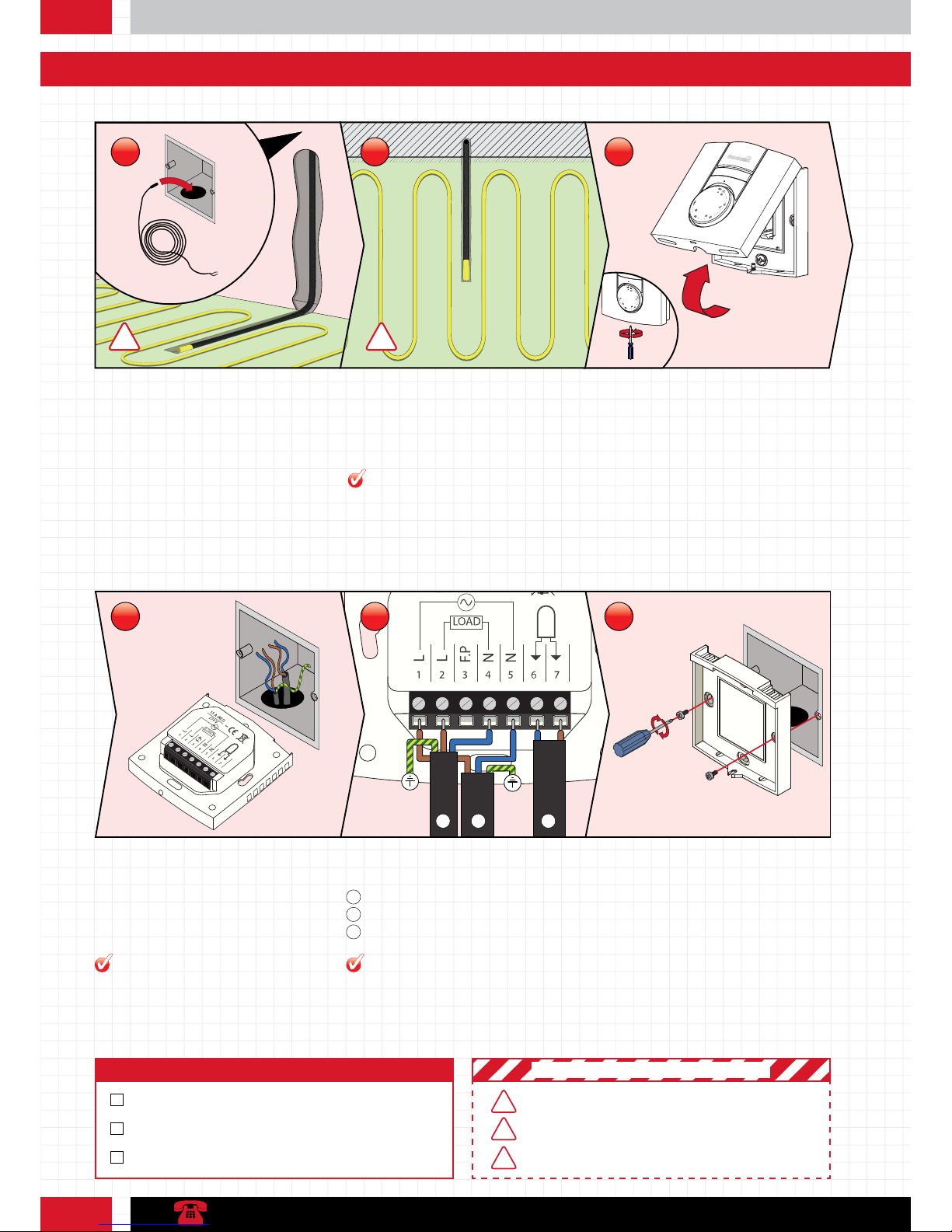
Stage 1: How to install your thermostat
Cavity wall: Position the conduit into your back
box and feed it down through the wall cavity.
Then feed your sensor probe cable down to the
end of the conduit.
Concrete wall: Chase a channel out of your
wall and floor, then lay the conduit in place.
You will need to plaster over the top. Now feed
the sensor probe into the conduit.
The conduit and sensor should be positioned
centrally between two runs of heating cable to
allow for an accurate temperature reading.
Step 1: Conduit Installation Step 2: Getting an even temperature Step 3: Loosen the face plate
1
3
2
°F
MO
P
M
TU WE TH FR SA SU
Fix the 5260 to the wall with the 3.5mm
screws provided. To complete your installation
mount the Face Plate in position and tighten
the screw under the base (reverse the
processes in step 3).
Step 6: Fix Base to Back Box
Sensor probe
1
Heating cable cold tail
2
Power supply
3
Pilot wire
Pilot wire
Pilot wire
Pilot wire
Energy
Manager
Home automation
system/ remote
System controlled
by pilot wire
Max. 10 units
per pilot wire
Earth
Earth
Pull the wires through from your heating
system and expose if required. Loosen the
tension screws to allow the wires to be
inserted and fixed.
Wire your thermostat as above.
Step 4: Wire your Thermostat Step 5: Wiring Schematic
!!
Leave the yellow cap on your conduit and
ensure sensor probe is pushed to the end.
PRO TIP
MAKE SURE CONDU IT AND SEN SOR ARE POSITIONED
CENTRALLY BETWEEN 2 RUNS OF HEATING CABLE
ENSURE THAT THE WIRI NG OF YOUR TH ERMOSTAT IS EXACTLY
THE SAME AS TH E DIAGRAM IN STEP 5
! IMPORTANT SAFETY PRECAUTIONS !
Checklist
CONDUIT IN SUITABLE POSITION
SENSOR CABLE INSTALLED
WALL PLATE INSTALLED IF NECESSARY
ENSURE CIRCUIT IS PR OTECTED BY AN ADEQUATE RCD
1
5
2
6
3
!
!
!
If you are installing 2 or more heating mats
connect the wires to a marshalling box
(5276) and take single feeds from terminals
L2 and N4.
The terminals accept wire thicknesses
between 0.33 and 3.1mm
2
. Use a cable
stripper to ensure a sufficient amount of
cable is exposed.
PRO TIPPRO TIP
Stage 1: How to install your 5260 thermostat
1 2 3
L1L2F.P3N4N
5 6 7
LOAD
15 A (RES)
230 V
Earth
Earth
4
 Loading...