

THERMOSTAHL PYROGAS 23, PYROGAS 47, PYROGAS 35, PYROGAS 58, PYROGAS 69 Instruction Manual
...
Gasification boiler
PYROGAS
INSTRUCTION MANUAL
ver. 1.1

THERMOSTAHL would like to thank and congratulate you on your purchasing
this boiler device and ensure that you have made a good choice. PYROGAS
boiler is a fail-proof product made of the highest quality materials by the large,
known and reliable production factory. THERMOSTAHL brand guarantees
satisfaction for the customer.
Please read this Operation and Maintenance Documentation (OMD) and get
familiarized with the terms and conditions of the guarantee before installing
and operating the boiler.
1. GENERAL INFORMATION
The Operation and Maintenance Documentation constitutes an integral part of the
boiler and should be delivered to the user with the device.
Installation should be carried out in accordance with the recommendations contained
in this documentation as well as applicable standards and best construction
practices.
Operational use of the boiler based on this documentation shall guarantee safe and
failure-free operation and shall constitute the basis for possible guarantee claims.
The Manufacturer (Thermostahl) shall reserve the right to modify production
engineering, technical data, dimensions, appearance and boiler equipment without
prior notice.
THERMOSTAHL shall not be responsible for damages resulting from improper
installation of the device and for failure to comply with the terms and conditions set
forth in the Operation and Maintenance Documentation.
2. SCOPE OF DELIVERY (SHIPPING CONDITION)
PYROGAS boiler shall be delivered as follows:
1. The complete boiler body with the boiler doors and two ceramic plates,
2. Packaging with the casing, thermal insulation with harnesses and turnbuckles for
its clamping,
3. Control panel (charged separately),
4. Cleaning tools,
5. Technical manual.
3. TECHNICAL CHARACTERISTICS, INTENDED USE OF THE BOILER, TYPES
OF FUELS
PYROGAS boiler type is a low-temperature, steel water. It is designed to be fired by
wood and briquette. Boiler operation is based on the process of gasification. The
woods are placed on the upper combustion chamber of the boiler, where it is the
process of drying and preheating. The fan supplies primary and secondary air
necessary for combustion. The combustion takes place in a direction downwardly
because of reverse flame, in which the wood is gasified by forced air flow from the
primary air. Special ceramic plates accept the thermal loading amounting to 1200oC.
Flue gases are directed by gas tubes into the smoke chamber and subsequently to
the chimney. With the method of gasification achieved efficiency to 92% resulting in
fuel economy by 25-30% compared to a conventional wood boiler. Moreover there is
a very small amount of ash. When loading wood the user should open the damper

(by-pass) by the lever. The smoke will leave by the tamper to the chimney. All boilers
have heat exchanger for cooling the boiler and protect them in case of overheating.
The boiler design allows achieving high efficiency and the efficient combustion
guarantees minimum exhaust emission of harmful substances and fuel economy.
Combustion process
Phase 1: Drying of wood.
Phase 2: Gasification of wood at 450oC.
Phase 3: Burning of mixture of gasified woods with the secondary air at 560oC.
Phase 4: Combusting with increasing flame temperature at 1200oC, at the lower
combustion chamber.
Phase 5: Outlet the exhaust gases through the torch at 165oC.
3.1. Boiler design
Boiler Body
PYROGAS gasification boiler is made of St 37.2 steel plates according to DIN 1700.
Non-metallic parts are made of special materials with high temperature resistant and
designed in that way to have long life time and strength ant to protect the metallic
parts of boiler against the high temperatures.
The boiler is separated in 3 parts; The upper chamber for wood feeding, drying of
wood and gasification of wood, the ceramic plate where burning the gasified woods
with the secondary air and the lower combustion chamber where the flame transfers
the heat to the water. The produced flue gases are directed by three triangle paths
into the smoke chamber and subsequently to the chimney.
An air fan is equipped at the front side of boiler and supplies with primary and
secondary air the upper chamber and the area around the ceramic plate. The
quantity of air is controlled by two switches with screws, one for the primary and one
for the secondary air. The outer of the boiler body is coved with glass wool insulation
and metallic covers.
Doors
The boiler has 3 doors. The first one allows the access to the upper chamber. It is
used for the feeding of boiler with woods. The second one is the middle door and is
used for the cleaning of the openings for the primary and secondary air and also for
the inspection of ventilator and finally the third one is the lower door and is used for
cleaning of the bottom ash. The amount of bottom ash in the boiler is about 1 to 2%
of the total amount of fuels. The lower door is also equipped with a window for
inspection of flame during the operation of boiler.
Ceramic plates
The boiler is equipped with two ceramic plates. The ceramics are constructed to
resist at very high temperature. During the operation the temperature of flame
reaches up to 1200oC. The first one is a ceramic plate with jets where the secondary
air is mixed with the gasified woods. The second ceramic plate is placed at the
bottom of the combustion chamber, receives the flame with the high temperature,
protects the boiler against the high temperatures and transfers the heat equally to the
boiler water.

a. b.
a. ceramic with jets, b. ceramic plate
Smoke chamber
The smoke chamber is at the back side of boiler. The flue gases are directed down of
the ceramic plate and through an opening goes to the smoke chamber after a route
through 3 triangle paths. The triangle paths are in contact with the boiler water so the
flue gases transfer their heat to the water. After that the flues exhaust to chimney and
then to the environment.
The smoke chamber has also and a damper. The tamper connects the feeding
chamber with the smoke chamber. That helps the exhausts to leave from the feeding
chamber to the chimney and not to the boiler room during the start of boiler and
during the feeding process. The damper opens manually with a lever. Before the user
opens the door to fill the boiler with woods they should pull the lever to open the
damper. Then there is no danger to fill the boiler room with smoke and the user could
fill the boiler. When the user completes the filling of the boiler, closes the door and
pushes the lever. The damper closes and the gasification process starts.
The smoke chamber has four covers for cleaning and inspection.
3.2. Technical characteristics

1
Control panel
2
Dumber lever
3
Feeding door
4
Air fan
5
Primary air controller
6
Middle door
7
Secondary air controller
8
Combustion chamber door for inspection and cleaning
9
Flame inspection window
10
Smoke chamber
11
Smoke chamber cleaning cover
Τ1
Input of hot water
Τ2
Output of cold water
Τ3
Drain tap 1/2"
Τ4,Τ5
Safety serpentine connections
Τ6
Connection for temperature sensor
Ø1
Flue diameter
3.3. Technical data
Type
Power
Max
pressure
Water
capacity
Heating
surface
Weight
Combust.
chamber
volume
Wood
max.
length
kW
Mcal/h
bar
lit
m2
kg
lit
mm
PYROGAS 23
20
23 3 136
3,00
348
125
370
PYROGAS 35
30
35 3 154
3,31
390
151
470
PYROGAS 47
40
47 3 172
3,62
436
176
570
PYROGAS 58
50
58 3 191
3,93
482
201
670
PYROGAS 69
60
76 3 210
4,24
527
226
770
PYROGAS 81
70
81 3 238
5,27
581
251
870
PYROGAS 93
80
93 3 257
5,58
656
276
970
PYROGAS 116
100
116 3 285
6,05
728
314
1120
Type
Cooling
serpentine
(T4-T5)
Back
pressure
Min.water
inlet
temperature
Required
chimney
convection
Exhaust
gases
mass
flow
Internal
water
pressure
drop
(ΔT=20oC)
Max
burning
time
Efficiency
in
Pa oC
Pa
g/sec
mbar
h
%
PYROGAS 23
½
15-20
65
15-18
14-17
5-7
6-10
90
PYROGAS 35
½
17-22
65
19-22
16-23
5-7
6-10
91
PYROGAS 47
½
19-23
65
22-24
20-30
6-8
8-12
91
PYROGAS 58
½
20-23
65
24-28
25-37
7-9
8-12
91
PYROGAS 69
½
23-24
65
27-30
31-46
8-10
8-12
91
PYROGAS 81
¾
24-25
65
28-32
35-52
9-12
9-13
91
PYROGAS 93
¾
25-26
65
28-32
40-60
9-12
9-13
91
PYROGAS 116
¾
25-27
65
30-35
45-70
10-14
10-14
91

3.4. Dimensions
3.5. Fuels
PYROGAS boiler is designed to burn woods and briquettes. You should be very
carefully with the woods that you use for the boiler. PYROGAS gasification boiler is
designed to burn wood with a percentage of humidity up to 20% and briquettes,
which are made of wood only, with humidity up to 10%. Woods with high amount of
water create condensation in the boiler leading to corrosion. Be sure that the woods
that you will use are dry and the amount of humidity is under the allowable limits. Use
woods from oak, beech or pine and do not mix them in the feeding chamber. Use
only one kind of wood in every feeding. This will provide a constant combustion of
fuel.
Fuel
Heating
Value
Allowable
diameter
Max
percentage
of humidity
Allowable
ash
percentage
kWh/kg
mm
%
%
Woods
4 – 4,3
80-150
<20
-
Wood briquettes
5,2 - <10
<4
ATTENTION: Do not use inappropriate fuels. There is danger for the health and for
the boiler. Do not as fuels woods that contain chemicals or explosive materials, MDF,
household waste etc. Use only woods and wood briquette suitable for your boiler.
During the manual feeding of the boiler, you should place the woods with the smaller
diameter at the bottom and after the biggest woods. This will help start the boiler and
offers a smooth operation of boiler.
Type
Α Β C D E F G H I K Φ1
Τ1-
Τ2
T3- T4-
T5
Feeding
Door
Dimensions
mm
mm
mm
mm
mm
mm
mm
mm
mm
mm
mm
in
in
mm
20
670
1290
950
620
1460
90
1385
690
510
460
160
1¼ ½ 350x466
30
670
1290
1050
620
1460
90
1385
690
610
560
160
1¼ ½ 350x466
40
670
1290
1150
620
1460
90
1385
690
710
660
160
1¼ ½ 350x466
50
670
1290
1250
620
1460
90
1385
690
810
760
180
1½ ½ 350x466
65
670
1290
1350
620
1460
90
1385
690
910
860
180 2 ½
350x466
80
670
1290
1450
620
1460
90
1385
690
1010
960
200 2 ½
350x466
100
670
1290
1700
620
1460
90
1385
690
1260
1210
220
2½ ½ 350x466

4. Design and installation recommendations
The boiler (boilers) should be installed in the boiler room specially designated and
adapted for that purpose.
4.1. Boiler placement recommendations
The boiler should be placed in the vertical position.
The boiler should be installed as close to the chimney as possible.
All distances of the boiler (boilers) from the boiler room’s walls and the distances
between the boilers should ensure easy access to the boiler (boilers). The distance
of the boiler front from the wall should ensure assembly and disassembly of the
burner and cleaning of the smoke tubes.
4.2. Boiler room recommendations
The boiler room should comply with the requirements set forth in the PN87/B-
02411standard“Built-insolidfuelboilerrooms”.
Moreover, it should comply with requirements of “Technical conditions relating to
buildings” provided for in the Building Code (Official Journal No. 75 of 2000, item
690).
The dimensions of the boiler room should comply with the requirements
relating to heat loads, fire protection regulations and allow for them to be fitted out,
operated and maintained in compliance with the OHS regulations.
The minimum height of the boiler room:
for boilers to 100 kW - 2.5 m
for boilers from 100 to 230 kW - 3.0 m
for boilers from 230 to 400 kW - 3.5 m
for boilers over 400 kW - 4.0 m
The minimum distances of the boiler from the front wall:
for boilers to 100 kW - 1.5 m
for boilers over 100 kW - 2.0 m
The distance of the boiler from the rear wall should ensure proper access to
the boiler.
The minimum distances of the boiler from the side wall:
for boilers to 300 kW - 0.6 m
for boilers over 300 kW - 1.0 m
These distances should be twice as long from the side of the feeder.
Theboilerroom’sfloor should be:
dust-free and non-flammable (paved with terracotta tiles or painted),
laid out with an inclination to the floor drain or cooling well.
The boiler room should have natural exhaust ventilation carrying off the air
outside and supply of combustion air (the so-called“Z-shaped”ventilationduct)with
the outlet placed 0.3 m above the floor level.

The section area of the exhaust opening should be calculated making
allowance for the ventilation air flow to be at least 0.5 m3/h per 1 kW of the installed
nominated power.
The section area of the air supply duct should be calculated on the basis of
the quantity of air required for combustion, which should be 1.6 m3/h per 1 kW of the
installed nominated power and additional air required for the needs of the natural
ventilation (0.5 m3/h per 1 kW), which in total gives at least 2.1 m3/h per 1 kW of the
installed nominated power in the boiler room.
Use of mechanical ventilation is not allowed.
No flammable materials may be stored in the boiler room.
The boiler room should have window openings of the total area not less than
1/15th of the floor area.
Theboilerroom’sdoor should be madeofmetal,withoutdoor lock,opening
outside under pressure, with the clear width of min. 0.9 m.
4.3. Hydraulic system installation
The system should be installed in accordance with the applicable regulations
and best construction practices.
The boiler can only be operated in the open system heating installations,
The open pressure vessel should be placed 2-3 m above the highest point of the
central heating system and protected against frost.
No cut-off valves should be installed between the boiler and pressure vessel.
The boiler room’s hydraulic system should ensure minimum temperature of
return water to the boiler (for solid fuel and gas–60oC, for furnace oil-50oC*).
To this end, a mixing valve with the boiler pump must be installed of the capacity
of c. 40% of the nominal flow of water through the boiler.
A desludger or strainer should be installed in the return water system before the
boiler.
The temperature sensors of the systems protecting against exceeding the
allowable temperature should be installed directly on the boiler at its highest
point.
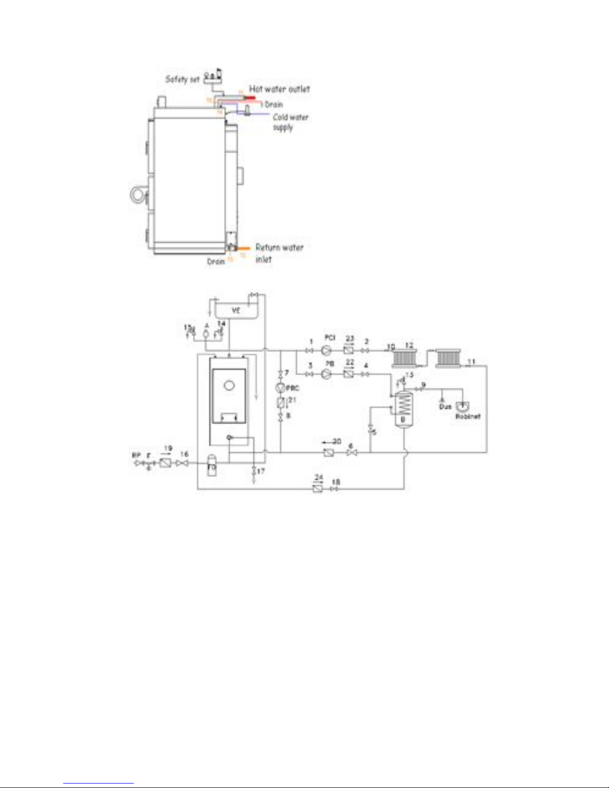
Hydraulic connections of boiler
Installation of boiler with open type expansion tank
Symbols
1,2,3,4,5,6,7,8,9
Ball valve
10,11
Radiator switch
12
Radiator
13,14,15
Safety valve
16
Automatic water fill valve
17
Drain tap
18
Cold water supply valve
19, 20, 21, 22, 23, 24
Check valve
Β
Buffer tank
VE
Open type expansion tank
PCI
Circulator of heating system
PRC
Recirculation pump
PB
Circulator for buffer tank
RP
Pressure reducer
F
Y-type strainer
A
Automatic air vent
FD
Water filter
Symbols
T1
Hot water outlet
Τ2
Return water inlet
Τ3
Drain tap 1/2"
Τ4
Heat exchanger input –
Connection with thermostatic
safety valve
Τ5
Output of hot water from heat
exchanger in case of boiler
overheating

Installation of boiler with closed type expansion tank
Symbols
1,2,3,4,5,6,7,8,9
Ball valve
10,11
Radiator switch
12
Radiator
13,14,15
Safety valve
16
Automatic water fill valve
17
Drain tap
18
Cold water supply valve
19, 20, 21, 22, 23, 24
Check valve
Β
Buffer tank
VE
Closed type expansion tank
PCI
Circulator for heating system
PRC
Recirculation pump
PB
Buffer tank circulator
RP
Pressure reducer
F
Y-type strainer
A
Automatic air vent
FD
Water filter
4.4. Installation safety
3 bar safety kit
It consists of a collector, manometer, safety valve and automatic air vent. It is fixed to
the input of hot water. For safety reasons, if not installed any of the following
protective systems must be installed and the second valve.
Regularly check the correct operation of safety valves. In case of wear or damage,
replace them immediately with new ones.
3 bar safety kit.

By-pass system with load units
Boiler has to operate for a temperature difference 10 to 15oC and to insecure that the
temperature of the return water is over 50oC. This insures the smooth operation of
the boiler and generally the right operation, the constant performance and the long
lifetime.
To insure that the temperature difference will be between 10 and 15oC the installation
needs a recirculation pump and a 3-way thermostatic valve. This system insures the
right temperature of return water and also the right temperature of water at the
radiators.
The ESBE series LTC100 is a load unit designed to protect the boiler from return
temperatures that are too low. Maintaining a high and stable return temperature
enables a higher level of boiler efficiency, reduced tarring and increased life span of
the boiler. The integrated pump offers boiler protection and optimal tank loading.
The LTC100 is used in heating applications where solid fuel boilers are used to feed
storage tanks.
The load unit consists of an integrated pump and thermic valve, designed to make
both assembly and handling easy. The load unit is protected by an insulation shell
and is fitted with easily readable thermometers.
The valve regulates on two ports, which makes it easy to install and does not require
any balancing valve in the bypass pipe.
The LTC100 has an integrated auto-circulation function which makes the unit
operational even during power failure or pump failure. The circulation function is
blocked at delivery, but can easily be activated if required.
The valve contains a thermostat which begins to open connection A at an outgoing
mixed water temperature in connection ABof50°C,55°C,60°C,65°C,70°Cor75°C.
Connection B is fully closed when the temperature in connection A exceeds the
nominalopeningtemperaturewith10°C.
ESBE LTC 100, load unit.
Overheating protection system
In a solid fuels installation with closed type expansion tank it is required to ensure the
protection against overheating, which mainly result from uncontrolled use of wood or
an electrical power failure.
When boiler temperature reaches 90-100oC the valve opens and allows the entry of
cold water into the heat exchanger serpentine. The heat exchanger is connected with
one thermostatic valve. The sensor is positioned into the boiler and when the
temperature of boiler reaches a temperature the valve opens and cold water come
into the serpentine. The cold water into the serpentine takes the heating of the boiler
and as a result the temperature of the boiler decreases. The hot water of the
serpentine goes to the drain. The valve responds directly to temperature differences

and its operation is complete mechanic without electric or spare parts. After the
decrease of boiler temperature under a limit the valve closes again and the water
stops to come into the serpentine.
If the web pressure is over 6 bar it is necessary to install a pressure reducer before
the installation. Noted that this valve does not replace the safety valve and it is
important to install safety valves too (at least 2).
Temperature and pressure relief valve
The T&P valve has a temperature sensor and provides double safety against
temperature (90oC) and pressure (3 bar). The output of the valve should be
connected with the drain for the disposal of the overheated water. The T&P valve
should be connected nearby to the boiler and necessary at the outlet. It provides
safety in case of closed type expansion tank installation but it is not replace the
overheating safety system.
Technical data:
Temperature (limit)
90οC
Pressure (limit)
3 bar
Connection
½”
Discharge rating:
10 kW
Dimensions
A B C D E F ½”
Ø15
40
102
88
39
4.5. Thermal protection of the boiler
The boiler should be operated within the supply and return water temperature
differences in the range of 10 – 15°C.
Because of the lifecycle of the boiler, it should be operated with the return
water temperature not lowerthan60°C.
In practice, it is difficult to meet this condition because the average
atmospheric conditions during the entire heating season “require” lower
settings.

In order to ensure the required return water temperature the following
solutions are suggested:
Higher settings on the boiler (possible only with low external temperatures).
Recommended
use of a mixing system based on the application of a three-way mixing valve
with a boiler circulator (the solution ensuring the proper temperature of both
the return water and the central heating system)
Boiler water requirements:
water for filling up boilers and heating installations should comply with the
requirements of the PN-93/C-04607 standard,
the boiler water should have the following parameters:
- pH value > 8.5
- total hardness < 20of
- free oxygen content < 0,05 mg/l
- chlorides content < 60 mg/l.
the used water treatment technology for filling up the heating installation
should comply with the requirements referred to above,
In the event of failing to comply with the above-mentioned requirements,
THERMOSTAHL may withdraw the guarantee for the installed boiler (boilers).
4.6. Chimney system
It should be installed as an acid-proof, double-wall, insulated chimney, or in
the case of chimneys made of brick, comply with the requirements of the
PN89/B-10425 standard; the technical parameters of the chimney should
ensure its protection against the effects of the condensate resulting from
cooling of the flue gas. Use of acid-proof chimney inserts (tin, stoneware, etc.)
is recommended.
The section of the chimney can be calculated following the formula provided
below:
D = 20(3+P)
1/2
[m2]; where: D-diameter in mm, P-boiler power rating in kW.
The chimney diameter may not be less than the diameter of the flue.
Connecting several boilers to one common chimney flue is not recommended.
The connection of the boiler to the chimney should be thermally insulated and
run the shortest possible way with the least possible number of pipe elbows,
with the appropriate height of the flue towards the chimney.
The chimney should be freely open towards the top and built at least 1 m
above the roof,
The diameter of the flue gas duct should be selected (calculated) in
accordance with the recommendations of the manufacturers of the chimney
inserts, however it should not be less than the diameter of the boiler flue.
Installation of an inspection door for removing combustion residues should be
envisaged,
The entire length of the chimney should be maintained clean,

Before connection the boiler to the chimney the user should obtain a positive
opinionofthechimneycleaners’specialist.
A graph for selecting the chimney diameter in relation to the boiler power rating and the chimney height, including
the provided values of the chimney draught.

4.7. Digital Electronic Controller PWC-1000
Operating instructions
Button A1 – A2 : They are used to increase and decrease the desired maximum
water temperature.
Button A3 : It is used for entering and exiting from the menu. For entering into the
menu short pressing is required, and for exiting long pressing.
Button A4 : It is used to turn on and off the controller (long pressing). It is also used
for starting and stopping the ignition process (short pressing).
After entering the menu buttons A1 and A2 are used to change the value of the
selected parameter, and buttons A3 and A4 are used to change the parameter we
want to alter.
Settings
01
TEMP.WATER
Maximum water temperature.
02
TEMP.EXHAUST
Maximum exhaust temperature.
03
TEMP.CIRCULATOR
Water temperature that the circulator pump starts to
operate.
04
TEMP.Bypass
Water temperature that the bypass valve starts to operate.
05
FAN AIR MAX
Maximum power amount of the fan (%) in the full burning
process.
06
DT WATER
Temperature difference below the maximum water
temperature that the fan power starts to decrease.
07
DT EXHAUST
Temperature difference below the maximum exhaust
temperature that the fan power starts to decrease.
08
IGNITION TIME
Maximumtimeoftheprocess“ignition”.Fanpoweris
determined onlybythe“ignitionair”settingatthisprocess.
09
IGNITION AIR
Power amount of the fan (%) in the ignition process.
10
Off TIME
Timethatexhausttemperaturemustbebelowthe“11-Off
exhaust”sothatthecontrollerissetinto“endoffuel”
process.
11
Off EXHAUST
Exhaust temperature value that determines when the fuel
has ended.
12
CONS.PERIOD
Repeatingtimeoftheprocess“flameconservation”.Inthis
processthefanpowerworksat“09-ignitionair”sothatthe
flame is conserved.
13
CONS.DURATION
Durationoftheprocess“flameconservation”.

5. Operation and maintenance
5.1. Start of the boiler
Before firing the boiler ensure the following:
The installation is complete and correct and there is any problem at the
hydraulic network.
The electrical installation is complete and correct.
The connection of flue gas tube is correct without problems and with the
suitable insulation.
The sensors are well positioned to the boiler.
The hydraulic network is complete and there is the correct pressure.
The circulator is connected and working properly.
The expansion tank is connected properly and ensures enough expansion of
the water.
The boiler valves are open.
There is sufficient ventilation of the installation.
No flammable or explosive materials around the boiler.
If you notice any damage or malfunction at the boiler contact your installer or the
company.
Use as fuel wood or briquettes. Make sure the wood is dry (humidity <20%) to ensure
better combustion, better performance and protect the boiler. Note the size of the
woods. Make sure the length is such that it fits in the feeding chamber. If there are
larger than the length of the chamber cut them.
First start of the boiler
The ceramic plates which are inside the boiler have a quantity of water inside their
structure from the production process. The water is evaporated during operation of
the boiler. But at the first operations, the boiler should not be working at full load,
because the water content can be vaporized and create gaps in the ceramic structure
that will lead to cracks and possible breakage of the ceramic plates. So it is
recommended the heating of ceramic plates to evaporate the water content and then
operate at full load.
The process for removing humidity from ceramic is as follows: Place a small amount
of kindling and a few small woods into the upper (feeding) chamber. Open the
damper of the upper chamber with the help of the special lever that is on the front
side and the upper right of the boiler. Be sure that you do not fill the boiler with
woods, but put a small quantity of woods, enough for 20 to 30 minutes of
combustion. After the operation allow the boiler to cool for 2-3 hours and repeat the
process. It is recommended to repeat the process 3 times to ensure that the
ceramics are dry.
If the boiler is not used in summer then the process will be repeated again before the
start of use.
Start of the boiler
Before starting the boiler check the whole installation and that it complies with all
safety rules. Pull the lever at the front and upper - right part of the boiler and open the
damper of the boiler. Open the feeding door and put some firelighters, some twigs
and some thin woods at the bottom of the feeding chamber, on the ceramic plate and

ignite them. Close the feeding door and open the third door to provide air. When the
woods are on fire feed the boiler with woods. During feeding insert woods with
smallest diameter on the bottom and the biggest on the top. Ensure that the woods
are on fire and close tightly the doors of the boiler. Close the dumber pushing the
lever and start the ventilator. Ensure that the doors are closed and there not leave
smoke or sparks.
5.2. Combustion settings
The flame should have suitable dimensions and cover the combustion chamber. The
effective operation of the boiler depends largely on the settings of primary and
secondary air.
If the primary air is excessive, much ash will fall into the combustion chamber. The
flame will be very strong and fast and make noise while wood consumption would be
high.
If the primary air is not enough then the flame will be low and slow and moving by air
currents and will be attracted by the chimney. It will not cover the entire surface of the
chamber, while the production of ash will be small.
If the secondary air is excessive then the flame is small and blue.
If the secondary air is enough then the flame would be great, embracing the entire
combustion chamber and will be red and opaque.
5.3. Maintenance
Daily maintenance
On a daily basis you need to check the integrity of the boiler room and the correct
operation of the boiler. Check that the pressure in the network is correct and that all
safety devices are in good condition and functioning properly. The boiler should be
cleaned daily by the combustion residues (ash and unburned residues). Clean both
upper chamber and combustion chamber. Clean walls and ceramic plate on the
upper chamber and throw the ash in the combustion chamber. Remove the ash from
the combustion chamber. CAUTION! The ash may contain hot residues which may
cause fire in the final disposal. Finally, check the integrity of the ceramic plates.
Weekly maintenance
Weekly cleaning of the boiler includes thorough cleaning of the combustion chamber
and the upper chamber. Open the dumber and then open the feeding door, wipe the
ash from the chamber and throw it to the combustion chamber. With a brush clean
ceramic plate lying between the two chambers. Ensure that ashes do not include hot
residues before its disposal. Use a scraper for cleaning the walls of the chambers of
any deposits. If ashes have accumulated underneath the ceramic plate in the
combustion chamber, remove it and clean the chamber. Refit the ceramic in the
chamber with special attention to proper placement. Before you clean, leave the
boiler switched off for at least one or two hours to cool. In continuous operation, it is
recommended to be cleaned once every 4 days.
Monthly maintenance
During the monthly cleaning clean the smoke chamber. The smoke chamber has
openings for cleaning. Unscrew the screws and clean the deposits of ash. With a
scraper remove smoke and ash from the walls of the smoke chamber. Collect them
of the side opening. After the cleaning, close the openings tight. Check the tightness
of the openings and the condition of the sealing cord. Replace it if it is necessary.

Season maintenance
Finally, during the annual maintenance of the boiler at the end of the period of use
(spring) check the entire heating system (boiler, piping, connections, valves, etc.) in
order to function correctly. Repair any damages or harms to the network. Clean
thoroughly the boiler, ceramic plates, the smoke chamber, the chimney, and
additionally clean the fan of any existence ashes inside.
6. Defects – Troubleshooting
Type of defect
Cause of defect
Procedure
Backflow of flue gas
into the boiler room
1. Blocked chimney, no or weak chimney
draught.
2. Improper supply and exhaust
ventilation of the boiler room.
3. Incorrectly adjusted boiler fan.
4. Improper boiler start-up.
5. Incorrect connection of the boiler with
the chimney.
6. Incorrectly closed, adjusted boiler door.
1. Measure the chimney
draught, clean the chimney,
check the combustion
parameters, λ=1,8-2,0.
2. Check the operation of the
supply and exhaust ventilation.
3. Adjust the fan.
4. Fire the boiler in accordance
with the manual.
5. Make a proper connection of
the boiler with the chimney.
6. Check whether the boiler door
seal adheres to the boiler on its
entire length.
Low temperature water
in the boiler despite
intensive burning
1. Improper fuel – too low calorific value
or damp fuel.
2. Incorrectly selected boiler in relation to
the size of the building.
3. No/weak chimney draught.
4. Incorrect adjustment of the boiler
settings.
5. Improper or blocked air supply
installation.
6. Too low quantity of primary air.
1. Use fuel of high calorific value
and moisture content in
accordance with the manual.
2. Check selection of the boiler
and the system.
3. Check whether the
combustion chamber, smoke
tubes and chimney are not dirty,
clean them.
4. Adjust the boiler.
5. Check the condition of the air
supply installation.
6. Adjust or clean the fan.
Boiler temperature too
high
1. Water loss in the system.
2. Blocked circulator/ electricity supply
problem.
3. Overloading of boiler.
1. Admit water – after cooling of
the boiler.
2. Check the circulator/check
that the electric parts are
appropriate connected.
3. Do not feed the boiler, wait
until the boiler temperature drop.
Too high temperature
of the flue
1. Too high chimney draught.
2. Incorrect heat transfer due to dirty
combustion chamber.
3. Incorrectly selected, too small boiler
power rating.
1. -Check the chimney system
whether is suitably selected.
- Close the dumber in case that
you forget it open.
2. Clean the combustion
chamber and smoke tubes.
3. Check the appropriateness of
boiler selection in relation to the

building.
Too high consumption
of fuel
1. Incorrectly installed central heating
system.
2. Incorrect selection of the boiler in
relation to the building.
3. Fuel of low calorific value.
4. Improper parameters of boiler
operation.
1. Check the central heating
system.
2. Carry out a short energy audit
3. Replace the fuel with the
appropriate fuel.
4. Set proper parameters for
boiler operation.
Flame image
1. red
2. blue
3.with noise
4.small flame
1. Lack of secondary air.
2. High secondary air supply.
3. High primary air supply.
4. Lack of primary air.
1. Increase the supply of
secondary air.
2. Decrease the supply of
secondary air.
3. Decrease the supply of
primary air.
4. Increase the supply of primary
air.
The chimney smokes
1. Low secondary air supply
2. If it still smokes...
1. Completely open of
secondary air opening
2. …completelyopenof
secondary air opening and
reduce the primary air supply.
Condensation inside
the boiler
1. Condensation of air and exhaust gases
during ignition of the boiler
2. Very low return temperature
3. Fuel with very high amount of moisture
4. Low chimney draft
5. Small section of chimney
6. Faulty connection to the chimney
7. Concentrates or rain entering the
chimney
1. During ignited adjust the
boiler temperature above 70oC
and keep it for a few hours
2. The boiler must be protected
from low return temperature with
a three-way valve. The minimum
return temperature is 50oC.
3. Use dry fuel with
moisture<20%
4. Check the chimney and clean
it if it is necessary
5. Check the sizing of the
chimney in accordance with the
instructions
6. Ensure tight connection of the
boiler to the chimney
7. Check the installation of the
chimney and place protective
hat if it is necessary
The fan does not start
1. Fan failure
2. Burned out fan
1. Check electrical connection of
the fan.
Check the capacitor of the fan
engine.
2. Replace the fan with a new
one.
Poor combustion
1. The fan feeds too little air
2. Too little chimney draught
3. Incorrect air supply system
1. Clean the fan, adjust the
quantity of air with the adjusting
screw.
2. Measure the chimney
draught.
Install a draught generator.
3. Check the patency of the air
supply duct.
 Loading...