


MULTIFUEL BIOMASS BOILER
ECOBIO
INSTALLATION AND USER MANUAL
VERSION:
2.2
UPDATE:
20.08.2017

Contents
1. GENERAL INFORMATION ................................................................................... 3
1.1. Proper use of the appliance ................................................................................ 3
1.2. Safety warnings ................................................................................................ 3
1.3. Data label ........................................................................................................ 3
1.4. Document information ....................................................................................... 3
2. TECHNICAL FEATURES AND DIMENSIONS ......................................................... 4
2.1. Technical features ............................................................................................. 4
2.2. Function principle .............................................................................................. 5
2.3. Dimensions ...................................................................................................... 6
2.4. Fuel ................................................................................................................. 7
3. BOILER MOUNTING ........................................................................................... 8
3.1. Transportation and delivery ................................................................................ 8
3.2. Boiler room ...................................................................................................... 8
3.3. Chimney .......................................................................................................... 9
4. INSTALLATION ................................................................................................ 11
4.1. Hydraulic connections ...................................................................................... 11
4.2. Return temperature protection .......................................................................... 11
4.3. Filling the system ............................................................................................ 11
4.4. Automatic ignition system ................................................................................ 12
4.5. Connection diagrams ....................................................................................... 13
5. ELECTRICAL CONNECTIONS ............................................................................ 14
5.1. General instructions ......................................................................................... 14
5.2. Version without automatic ignition ..................................................................... 14
5.3. Version with automatic ignition ......................................................................... 18
5.4. Connecting exhaust temperature sensor ............................................................ 22
5.5. Connecting temperature sensors ....................................................................... 22
5.6. Connecting weather sensor............................................................................... 22
6. BOILER START-UP ........................................................................................... 23
6.1. Initial lighting checks ....................................................................................... 23
6.2. Starting the boiler with wood ............................................................................ 23
6.3. Starting the boiler with pellet/biomass ............................................................... 24
6.4. Checks to carry after initial start-up .................................................................. 24
6.5. Manual fuel loading ......................................................................................... 25
6.6. Operation mode .............................................................................................. 25
6.7. Combustion regulation ..................................................................................... 25
6.8. Supervision mode............................................................................................ 26
6.9. Stop mode ..................................................................................................... 26
6.10. Chimney damper adjustment ............................................................................ 26
7. SERVICE AND MAINTENANCE .......................................................................... 27
7.1. Cleaning the boiler .......................................................................................... 27
7.2. Cleaning the chimney box ................................................................................ 28
7.3. Cleaning the furnace ........................................................................................ 28
7.4. Maintenance intervals ...................................................................................... 28
7.5. Basic service procedures .................................................................................. 29
7.6. Maintenance after long stop .............................................................................. 31
8. TROUBLESHOOTING ........................................................................................ 32
CE DECLARATION OF CONFORMITY ............................................................................... 33

GENERAL INFORMATION
3
1. GENERAL INFORMATION
1.1. Proper use of the appliance
Before you make use of this appliance make sure you have read and fully understood the
instructions included in this manual.
The installation and use of the appliance must be performed according to the instructions
indicated in this manual in combination with the current national safety regulations.
The appliance is designed for use in pumped hot water central heating systems. Any other use
is considered improper and is prohibited. THERMOSTAHL ROMANIA declines any responsibility
for damages or injuries caused by improper use; in this case the risk is completely at the user’s
responsibility.
To ensure an efficient and flawless function of the appliance, it is strongly recommended that
you have performed an annual service by a qualified technician.
1.2. Safety warnings
All installation and maintenance procedures must be carried out by professional and authorized
personnel, in compliance with the indications in the present manual and national regulations.
Any failure to correctly install this appliance could cause damage or injuries!
Do not make modifications to parts of the appliance, unless you have contacted the company
and an authorized service contractor.
Only original accessories and spare parts must be used to ensure correct and safe function.
Make sure you respect the cleaning and maintenance procedures on the corresponding intervals.
Failure to do so can cause malfunction to the appliance and possible damages.
The boiler is design to function on the fuels indicated in the corresponding paragraph. Any other
fuel is prohibited. Do not use explosive or flammable substances! Do not store such substances
inside the boiler room.
The working pressure varies according to the model. Make sure you use the appropriate water
pressure.
Working in a pressure higher than the one indicated in this manual is strictly
prohibited and dangerous!
1.3. Data label
The data label of the appliance is placed on the boiler’s side cover, on the external part. Make
sure that it is properly placed and readable.
On the label it is indicated the serial number and the manufacturing year of the appliance.
1.4. Document information
This document is an integral and indispensable part of the product and must be retained in good
condition by the user. Keep it in a safe place for future reference.
If the appliance is sold or transferred to another person, this manual has to always follow the
appliance and handed to the new user or installer.

TECHNICAL FEATURES AND DIMENSIONS
4
2. TECHNICAL FEATURES AND DIMENSIONS
2.1. Technical features
ECOBIO is an automatic multifuel boiler, specially designed for use with pellet, carbon, olive
husks, oats, and also manually wood. The furnance is specially designed for protection against
fire return. The fuel transportation is performed with a feeder, driven by a motoreducer and the
combustion air is delivered by a fan. Fuel is deposited into a silo of big capacity, which can
ensure autonomy from 3 up to 10 days.
The boiler is equipped with a modulating fan and a digital controller. The boiler can also control
the heating pump and the hot water pump, as well as being connected with an exhaust gas
temperature sensor for full fan modulation and maximum fuel savings.
The boiler is available in two versions: with manual fuel ignition and with automatic ignition
(version ECOBIO-R).
The ECOBIO boiler is a product designed to operate in economy mode, providing a constant
heating of houses or small industrial premises. It can be connected to radiators or heaters with
hot water.
The boiler is made of steel, ideal material for thermal fluctuations, resistant to expansion and
contraction with two passes of burned gases. Also this boiler is protected against thermal shock.
ECOBIO boiler is designed so that all surfaces that are in contact with the flame are cooled by
water, including the grate where the ash and combustion residues fall. The two roads flue at the
top, the large number of flue pipes, large volume of the furnace and boiler water as well, and
symmetrical construction causes a high yield
DESCIPTION OF BOILER COMPONENTS
Steel boiler body with cylindrical heat exchanger
Removable rear smoke box with inspection cleaning door
Upper door for ignition, fuel loading and cleaning access
Lower door for ash removal
Ash box positioned on the lower part of the fire chamber
Glasswool body insulation of 50 mm thickness
Electrostatically painted external covers
Digital control panel
DESCIPTION OF FURNACE COMPONENTS
Steel furnace body
Feeding auger welded to solid axis
Combustion air fan
Feeding motoreducer
Transmission system with chain wheels
Transmission system protection cover
Cast iron combustion plate
Ignition element (optional)
Fuel silo with protection frame and shuttering lid

TECHNICAL FEATURES AND DIMENSIONS
5
2.2. Function principle
2.2.1. Boiler
The function of the ECOBIO boiler is based on exhaust gas
evacuation through the chimney. The fuel is positioned on the
grate. The combustion takes place in the fire chamber. During
the combustion the flame comes in contact with the side walls
of the fire chamber, which are surrounded by water. The fire
chamber is of big volume in order to receive big dimension
logs and to ensure a long autonomy.
The combustion air is supplied by the fan and distributed
through the furnace plate. The fuel feeding is regulated
through an auger which is moved by a motoreducer.
The exhaust gases are guided through the heat exchanger to
the smoke box, and afterwards evacuated to the chimney.
The smoke box is equipped with an inspection and cleaning
door, which also actions as an explosion relief.
The doors have an insulation cord to ensure air-tight closing.
Each door is equipped with a handle, which must always be
well tightened during the combustion.
Fig 1. Boiler function
2.2.2. Furnace
The ECOBIO boiler is equipped with the innovative biomass furnace BIOFIRE. The system is
consisted of two axes (BI-AX): The lower axis is the main one, feeding fuel to the furnace, while
the upper is the secondary, transporting the fuel from the silo to the main axis. Between the two
axes there is a safety DROPBOX device. This device has a metal flap that automatically closes
with a spring when the feeding stops. This way the danger of blockage and backfire is eliminated.
The motoreducer is mounted on the lower axis, and the transmission is realized through chain
wheels. A metal protection cover is placed around the transmission system.
The combustion air is supplied by the fan mounted on the furnace. In case the optional ignition
system is installed, there is an ignition element mounted in the air pipe, close to the furnace
plate.
Legend
1
Silo flange
2
Fuel box
3
Upper feeding axis
4
Transmission chain
5
Motor
6
Reducer
7
Support leg
8
Fan
9
Boiler flange
10
Lower feeding axis
11
Air chamber
12
Fuel DROPBOX
13
Cast iron plate
14
Feeding pipe

TECHNICAL FEATURES AND DIMENSIONS
6
2.3. Dimensions
Boiler
Type
Feeding
door
H
W1 W F L A
T1-T2
T3
T4
T5
mm
mm
inch
ECB 15
340x360
1205
530
1280
916
940
1160
1½”
Ø180
¾”
½”
ECB 20
340x360
1205
530
1280
916
1040
1160
1½”
Ø180
¾”
½”
ECB 25
340x360
1205
530
1280
916
1140
1160
1½”
Ø180
¾”
½”
ECB 30
340x360
1205
530
1280
916
1240
1160
1½”
Ø180
¾”
½”
ECB 40
340x460
1320
670
1300
1016
1100
1300
2”
Ø220
¾”
½”
ECB 50
340x460
1320
670
1300
1016
1200
1300
2”
Ø220
¾”
½”
ECB 60
340x460
1320
670
1300
1016
1300
1300
2”
Ø220
¾”
½”
*Nominal output is obtained with good quality wood pellet, with 4,9 kWh/kg calorific power and
10% humidity.
Furnace type
ECOBIO 15-30
ECOBIO 40-60
Fan
Type RV-12RKs
RV-12RK
Power W 35
70
Air debit
m3/h
170
240
Pressure
Pa
280
310
Voltage
V/Hz
230/50
230/50
Noise level
dB
<60
<60
Protection
IP 20
IP 20
Motor
Type
EWM 30-50/300
EWM 30-50/300
Power W 180
180
Voltage
V/Hz
230/50
230/50
Protection
IP 54
IP 54
TECHNICAL DATA
Boiler
Type
Nominal
Output*
T
max
P
max
Effici
ency
Water
contents
Fire
chamber
length
Silo
volume
Fire
chamber
volume
Weight
kW
o
C
bar % lit
mm
lit
m3
kg
ECB 15
15
90
2
88
65
450
220
0,14
265
ECB 20
20
88
80
550
0,17
290
ECB 25
25
88
95
650
0,20
315
ECB 30
30
88
115
750
0,23
340
ECB 40
40
88
135
700
340
0,32
445
ECB 50
50
88
155
800
0,36
475
ECB 60
60
88
175
900
0,41
525

TECHNICAL FEATURES AND DIMENSIONS
7
2.4. Fuel
The ECOBIO series is designed for automatic function with solid fuel of biogenic or fossil nature,
with granulation up to 30mm and humidity up to 20%. The boiler is also able to be used on wood
or other solid fuels with manual feeding, without any modification.
This means different types of biomass fuels, such as pellet, agropellet, olive husks, fruit kernels,
cereals, granulated carbon. When the fuel used has characteristics that significantly vary from
nominal (i.e. carbon, cereals, agricultural residues), they must be used in combination with pellet
or agropellet at a 50:50 ratio. If you want to use solely carbon as fuel, please contact the
manufacturer.
The fuel with the best quality, concidering calorific power, ash content, humidity and
standartization, is wood pellet. The less quality of the fuel, the more fuel supply must be provided
to achieve the nominal power and of course the most the consumption and the ash remains.
The nominal characteristics of the boiler are calculated for use on wood pellet!
Fuel type
Calorific power
Max diameter
Max humidity
Ash content
kWh/kg
mm % %
Pellet
4,8
6 – 8
<10
<1
Agropellet
4 – 4,2
6 – 10
<10
<5
Coal
5,3 – 6,5
3 – 25
<15
4 – 8
Lignite
1,6 – 3,8
3 – 25
<20
<10
Cereals (oat)
4,2
3 – 6
10 – 13
0,6
Wood chips
4,3
5 – 25
<20
4 - 6
Barks
2,6
5 – 25
<20
8 - 10
Wood
4 – 4,3
-
<20
4 - 8
Wood briquette
5,2
-
<10
<4
Table 1. Characteristics of different types of fuels
Every type of biomass fuel contains a significant amount of humidity, which highly affects its
combustion behaviour and calorific value. Boiler output, efficiency and autonomy will significantly
diminish as the humidity increases. The nominal data presented in this manual are calculated for
humidity content 10%. Maximum allowable humidity content is 20%. If the fuel has bigger
humidity, the combustion will be highly imperfect, causing problems to the furnace and the feeder.
In order for the feeding and combustion system to function properly the maximum
allowed humidity of the fuel is 20%!
It is prohibited the use of explosive, inflammable materials, plastic, domestic
residues, etc.
It is prohibited to manually feed solid fuel in the boiler simultaneously with the
furnace function!
Use of cereals is allowed only in mix 50:50 with pellets!
Use of coke, hard coal, briquetted coal or brown coal is forbidden without
consulting the manufacturer!

BOILER MOUNTING
8
3. BOILER MOUNTING
3.1. Transportation and delivery
The boiler is delivered on wood pallet, well fixed with screws. Remove it carefully by unscrewing
the screws. The loading and unloading of the boiler must be performed with a forklift or a crane.
The boiler is very heavy. Do not try to lift by hands or other unsuitable
equipment. Danger of injury! Perform all moves with extreme caution.
Remove the boiler packaging with attention. Keep the packaging material away from
children since it can be dangerous. After having unpacked everything, make sure that the
appliance is intact and undamaged. In case of doubt do not use the appliance and inform the
supplier.
The ECOBIO boiler is delivered with the following equipment already fitted and mounted:
Steel body boiler
Glasswool insulation mounted on the boiler body and tightened with plastic tapes
Metal covers mounted on the boiler body
Furnace mounted on the side flange with all necessary equipment
Silo for fuel with air-tight lid
Cast iron grates for wood combustion
Turbinators positioned inside the fire tubes
Digital control panel
Cleaning tools
In the documentation folder you will find:
Technical manual
Warranty leaflet
3.2. Boiler room
3.2.1. General requirements
The boiler must be installed in a special and separate room. This room must be chosen so that
it offers easy access for fuel transport, air supply and exhaust gas evacuation. The doors of the
boiler room must be metallic, open outwards, and have at least 0,9 m width.
The boiler installation is prohibited in rooms with extensive dust, dangerous
gases, and moist spaces.
For the correct boiler function it is necessary that the boiler room has openings for natural
ventilation and combustion air supply. It is recommended that two different openings are used
for this purpose, positioned on opposite walls and diagonally to ensure good air circulation. The
total surface of the openings must be at least 1/12 of the boiler room surface. Forced ventilation
is prohibited in the boiler room.
The boiler room must be provided with a drainage channel. All safety devices must be connected
to this channel.
The boiler room must have an appropriate fire extinguishing system, according to the regulations
in force. In case that the building is designed with a fire alarm system, a smoke detector must
be positioned on top of every boiler.
The fuel storage is prohibited in the boiler room. If so, the storage must be separated from the
boiler with a non-flammable wall, and proper distanced from the boiler.

BOILER MOUNTING
9
3.2.2. Boiler room dimensions
The boiler must be placed on a horizontal plane, with adequate mechanical resistance to support
the boiler’s weight. The boiler must be positioned in the room in such a way so that it is easily
accessible from all the sides. The following dimensions are recommended (see 0):
The distance between the boiler and the back wall is the proper distance that allows easy access for
inspection and maintenance.
The distance between the boiler and side wall - at
least 0.6 m.
The height of the boiler room - at least 2 m.
Access in the boiler room of strangers to the
operation of boilers and auxiliary installations is
prohibited.
Access and service spaces of boiler room and hall
doors paths will always be free.
In the boiler room will be displayed operating
instructions, taking into account the specificities of
the boilers mounted. Also, you will see internal
instructions of staff and service duties.
Fig 2. Boiler room dimensions
3.3. Chimney
The chimney installation must supply sufficient draught, air tightness and protection against
condensation.
The appropriate chimney installation is very important for the boiler’s efficient
and safe function!
The chimney must be positioned if possible in the interior of the building. It must be vertical,
with no changes in the direction. The cross-section of the chimney can be round or rectangular.
If the chimney is installed in the exterior, it must be insulated.
The horizontal part connecting the boiler’s chimney pipe with the vertical chimney must have
maximum length 2 m. If this distance is bigger, it is recommended to have a 15-30o inclination
upwards. The connection with the boiler’s chimney pipe must be air-tight.
The chimney must be equipped with a cleaning door at its base. Also cleaning doors are
recommended where there are changes in direction and ash can be accumulated. Tactical
cleaning is recommended (every 3 months) for efficient boiler function.
A chimney terminal must be installed at the end of the chimney for protection against weather
effects and foreign objects entrance. In areas with strong winds a special anti-downdraught
terminal is recommended.
The chimney height must exceed the roofline by at least 1 m. If there are other obstacles
positioned on the roof, the chimney height must exceed them by at least 1 m. If there are
multiple chimneys, minimum distance between them is 0,3m.

BOILER MOUNTING
10
Each boiler should be connected to an independent chimney. Connection of multiple
boilers to the same chimney is not recommended.
Fig 3. Chimney distances
Fig 4. Chimney connection

INSTALLATION
11
4. INSTALLATION
4.1. Hydraulic connections
The boiler is intended for connection with an open expansion vessel network. The boiler can be
connected also with closed expansion vessel, if it is equipped with an overheating serpentine
(optional).
The boiler is intended for maximum working temperature 90oC and maximum pressure 2 bars.
When connected with a closed expansion vessel, its volume must be chosen double to a similar
installation on liquid or gas fuel.
If a connection pipe is not used, it must be sealed before water fill!
4.2. Return temperature protection
For the correct function of the boiler and for protection against corrosion it is very important to
ensure steady temperature at the return of the boiler of at least 55oC.
This can be ensured by installing a recirculation pump between the boiler outlet and return (see
connection diagrams).
An alternative variation is by installing at the return of the boiler a three-way thermostatic valve.
Having a return temperature less than 55oC is very dangerous for the boiler longlife and can cause warranty loss!
4.3. Filling the system
After completing all the hydraulic connections, the circuit may be filled with water. After filling
the system, open the radiators air valves to get rid of the air in the installation.
Verify that the installation pressure is according to the technical feature of the boiler. The
pressure must be verified through the boiler’s manometer. An additional manometer should be
installed on the cold water inlet to verify the cold pressure, at the lowest point of the installation,
at a point close to the boiler.
The whole installation must remain under nominal pressure for at least 10 minutes. During this
period, check that all the connections are tight and there are no water leakages. Make sure that
during this period no pressure drop appears.
Legend
T1
Outlet
T2
Return
T3
Chimney pipe
T4
Safety kit connection
T5
Discharge valve connection

INSTALLATION
12
After firing the boiler, make sure the network functions properly at working temperature and
pressure.
The hardness of the mains water supply affects the boiler’s life span. It is
recommended to use a water softener if water hardness exceeds 5oG.
Do not fill the system at the working pressure! When the boiler will be heated,
the water pressure will raise. Filling pressure must be at least 1 bar lower than
working pressure!
4.4. Automatic ignition system
As an optional, the furnace can be provided with an automatic ignition system. This consists of
the following:
Ignition element 500W
Control panel Ecomax 800P
Exhaust temperature sensor
The ignition element is installed in a special inox tube casing, positioned under the furnace cast
iron plate. The cables are protected with a silicon layer, resistant to temperature up to 300oC.
All the electrical connections are prewired.
The controller is equipped with an exhaust temperature sensor. This must be installed on the
chimney, at a distance maximum 1m from the boiler.

INSTALLATION
13
4.5. Connection diagrams
4.5.1. Open expansion vessel connection
Legend
1-9.
Separation valves
B
Hot water boiler
10,11.
Radiator valves
VED
Open expansion vessel
12.
Radiators
PCI
Central heating pump
13-15.
Safety valves
PRC
Recirculation pump
16.
Filling valve
RP
Pressure reducer
17.
Drainage valve
F
Filter
18.
Cold water valve
A
Air relief valve
19-24.
One-way valves
FD
Water softener
4.5.2. Closed expansion vessel connection
Legend
1-9.
Separation valves
B
Hot water boiler
10,11.
Radiator valves
VE
Closed expansion vessel
12.
Radiators
PCI
Central heating pump
13-15.
Safety valves
PRC
Recirculation pump
16.
Filling valve
RP
Pressure reducer
17.
Drainage valve
F
Filter
18.
Cold water valve
A
Air relief valve
19-24.
One-way valves
FD
Water softener

ELECTRICAL CONNECTIONS
14
5. ELECTRICAL CONNECTIONS
5.1. General instructions
All electrical connection must be performed by an authorized professional, in conformity with the
local regulations and the indications of this manual. Connections must be done according to
norms EN 60529 and EN 60335-1, and protection norms IP 40 and IP 44.
All wiring must be waterproof insulated. Exposed cables should be protected within plastic
channel. The main electrical supply of the boiler must be connected to an independent safety of
max 16A. The boiler room lighting must be on a separate circuit.
The user is obliged to connect the boiler to an efficient grounding system.
THERMOSTAHL ROMANIA SRL declines any liability for damage caused to
people, animals and goods, due to defects caused by faulty electrical
connections or lack of connecting the boiler to an efficient grounding system.
5.2. Version with manual ignition
5.2.1. Description of buttons and display
After turning the regulator on, the START and STOP buttons are used to enable and disable
airflow respectively.
The regulator provides SUPERVISION function that is activated automatically.
Legend
1.
“F” button:
-short press – access the menu
-long press – exit submenu
2.
STOP button:
-short press – decrease value
-long press – burning stop
3.
START button:
-short press – increase value
-long press – starting the boiler

ELECTRICAL CONNECTIONS
15
5.2.2. Description of the main display screen
Icons:
Legend:
1. Preset boiler temperature.
2. Measured temperature of boiler.
3. Signal arrow.
4. SUMMER – hot utility water mode
symbol.
5. PRIORITY - hot utility water mode
symbol.
6. Feeder operation symbol.
7. Room thermostat - this symbol lights up
when the temperature inside the room
reaches the preset value (contacts are
disconnected).
8. Alarm symbol.
9. Signal of increasing the preset boiler
temperature due to hot utility water
heating.
10.
Signal decreasing the preset boiler
temperature due to operation of the
room thermostat.
11. Service menu symbol.
12. Hot utility water temperature sensor.
13. Boiler pump symbol.
14. Hot utility water pump symbol (HUW).
15. Boiler temperature sensor.
16. Feeder temperature sensor.
17. Airflow power.
18. Fan operation symbol: not visible –
regulation is off; visible regulation is on;
flashes – the regulator is in the
SUPERVISION mode.
19. Hot utility water tank symbol.
20. Manual function on wood.
Temperature settings:
1 – preset boiler temperature
2 – measured boiler temperature
Central heating pump starting
temperature
Hot utility water pump starting
temperature
Feeding time in OPERATIONAL
mode
Break time in OPERATIONAl mode
Fan power in OPERATIONAL mode
Manual control
Setting hot utility water mode
operation:
1 – HUW priority,
2 – simultaneous operation of
pumps,
3 – SUMMER mode,
4 – HUW pump off.
- Return to factory settings
- Service menu symbol

ELECTRICAL CONNECTIONS
16
5.2.3. Electrical connections
Note: Do not use the ecoSTER room panel and room thermostat at the same time!
The regulator is designed to be fed with 230V~, 50Hz voltage. The electrical system should be
three core (with protective wire), and in accordance with applicable regulations. The grounding
cable should be connected to the terminals marked with the symbol .
The connection wires should not have contact with hot surfaces (with temperature exceeding
the nominal temperature of their operation). Terminals 1–10 are intended for connection with
low voltage (<15V) devices.
Connecting mains supply 230V~ to terminals 1–10 will damage the regulator
and creates risk of an electric shock!
Legend
1.
Control panel
2.
IEC socket for power supply of hot utility water (230V~)
3.
IEC socket for power supply of central pump (230V~)
4.
IEC plug
5.
Hot utility water pump
6.
Central heating pump
7.
IEC fan connector (230V~)
8.
IEC feeder connector (230V~)
T1.
Boiler temperature sensor (type CT4)
T2.
Hot utility water temperature sensor (type CT4)
T.
Room thermostat (opened=no heating / closed=heating)
DZT-1.
Additional thermal safeguard (type DZT-1 85°C or 90°C)
ecoSTER200.
Room panel with room thermostat function
STB.
Safety temperature limiter

ELECTRICAL CONNECTIONS
17
In order to connect the sensor or wire, take off the terminal
cover and screw cores of cables into the terminal. Press in the
sensor cable (1) into a pit (2). A slot (3) will be impressed on
the cable. Do not insert any metal elements nor wires
shielded with metal into the regulator. Maximum length of a
cable inserted into the regulator should not exceed 60mm. To
take off the cover just loosen the screw (4).
Electric cables cannot be close to nor touch hot
elements with temperature higher than 70°C.
Special attention should be paid to the distance
between cables and chimney duct. Electric shock
hazard!
5.2.4. Hydraulic function scheme
The presented hydraulic diagram does not replace the central heating system
design and it can be used for reference purposes only.
Brief description of the system functioning: after firing the boiler up, the central heating pump
is activated after the boiler exceeds the central heating pump activation temperature (service
parameter n0, by default n0=40°C). The hot utility water pump is activated when the
tank temperature (6) drops below the preset value. If at this time the preset boiler
temperature is lower than the preset hot utility water temperature, the regulator increases
the preset boiler temperature in order to fill the hot utility water tank.
After filling the hot utility water tank, the hot utility water pump can continue work for a preset
time, in order to collect heat from the boiler. After the room thermostat (5) operates, the
regulator decreases the preset boiler temperature and/or temporarily disables the central
heating pump (2).
Legend
1.
Regulator
2.
Central heating pump
3.
Hot utility water pump
4.
Fan
5.
Room thermostat
6.
Hot utility water tank
7.
Central heating system
8.
Feeder
9.
Boiler
T1.
Boiler temperature sensor
T2.
Hot utility water
temperature sensor
T4.
Burner temperature sensor

ELECTRICAL CONNECTIONS
18
5.3. Version with automatic ignition
5.3.1. Description of buttons and display
5.3.2. Description of the main display screen
Legend:
1. Regulator operation mode: FIRING-UP,
OPERATION, SUPERVISION
2. Preset boiler temperature
3. Measured boiler temperature
4. Field of factors influencing preset boiler
temperature: ,,T” - symbol of decreasing
preset boiler temperature from opening of
room thermostat contacts; ,,S” - symbol of
decreasing preset boiler temperature
according to decrease schedulle; ,,C” –
symbol of increasing preset boiler
temperature for the time of filling hot utility
water tank HUW; ,,M” symbol of increasing
the preset boiler temperature to fulfill mixer
circuit demands; ,,P” – weather control for
boiler cycle is active, „R” – indicates active
return protection
5. Fan operation symbol
6. Fuel feeder operation symbol
7. Central heating pump operation symbol
8. Domestic hot water pump operation
symbol
9. Measured temperature of domestic hot
water tank
10. Preset temperature of domestic hot
water tank
11. Clock and day of the week
12. Active lighter, the digit next to it means
the number of attempt to fire-up
13. External (weather) temperature
14. Current boiler output level
15. Warning symbol - disinfection of the hot
utility water tank is enabled
Legend
1.
MENU button
2.
TOUCH & PLAY knob:
-rotate to change value
-press to confirm setting
3.
EXIT button

ELECTRICAL CONNECTIONS
19
5.3.3. Activating the regulator
After enabling power supply, the regulator recalls its status at the moment of disconnecting the
power supply. If the regulator was not active before, it will start in the “stand-by” mode. In this
mode, the display is dimmed, and displays the current time, weather sensor temperature and
information: “Boiler off”.
It is possible to activate the boiler (press encoder knob and select setting), or to set its operation
parameters (MENU button) without the need for turning it on. After making sure that there is
fuel in the silo and that the silo lid is closed, you can turn the boiler on.
5.3.4. Setting boiler temperature
Preset boiler temperature can be set in the menu: Boiler settings > Preset boiler temp.
The value set as Preset boiler temp. is ignored by the regulator if the preset boiler temperature
is controlled by weather sensor. Regardless of that, the preset boiler temperature is
automatically increased in order to fill the hot utility water tank and feed heating mixer cycles.
5.3.5. Ignition
The FIRING-UP mode is used for automatic ignition of furnace in the boiler. Total duration of the
ignition process depends on regulator settings (feeder operation time, heater operation time,
etc.) and on the boiler’s status before firing-up.
If ignition is unsuccessful, another attempts to fire the furnace up are made, during which the
fuel dose (feeding time) is reduced to 10% of the first attempt dose.
After three unsuccessful attempts, an alarm Failed firing-up attempt is reported. In such case,
the boiler operation is halted. Boiler operation cannot be continued automatically - service crew
must intervene. After removing causes of impossibility to fire the boiler must be restarted.
5.3.6. Operation mode
In this mode the regulator operates automatically, according to the output settings. The fan
operates continuously, while the feeder is activated cyclically. A cycle consists of feeder operation
time and duration of feeding interval.
If, in the OPERATION mode, it becomes necessary to fill the HUW tank at preset boiler
temperature lower than temperature required to fill the tank, the regulator automatically
increase the preset boiler temperature for the time of filling the HUW tank.
The regulator is equipped with a boiler power modulation mechanism enabling to decrease its
power gradually along with boiler temperature reaching a preset value. A 3-level indicator is
displayed on the left side of the boiler icon which stands for the current one of three available
power levels. Parameters of the output levels are in the menu: Boiler settings > Output
modulation
Each of the levels - referred to as 100%, 50% and 30%, can be respectively attributed with
different fuel feeding time and airflow power, which translates into actual boiler output level.
When the boiler is supposed to operate at specific output level is determined by values called
hysteresis, H1 and H2 respectively. Each of these values relates to measured boiler temperature
relative to its preset value.

ELECTRICAL CONNECTIONS
20
5.3.7. Electrical connections

ELECTRICAL CONNECTIONS
21
5.3.8. Hydraulic scheme
Legend:
1.
Boiler
2.
Regulator (main module)
3.
Display
4.
Boiler temperature sensor
6.
Central heating pump
7.
Thermostatic 3-way valve
8.
Circulation pump
9.
External temperature sensor
10.
Collector
11.
Domestic hot water temperature sensor
12.
Domestic hot water pump
13,18,23,28.
Mixer servomotor
14,19,24,29.
Mixer pump
17,22,27,31.
Mixer temperature sensor
16,21,26,30.
Room thermostat of mixer zone
32.
Extension module for mixer
33.
Hot water boiler
The presented hydraulic diagram does not replace the central heating system
design and it can be used for reference purposes only.
The boiler regulator controls the central heating pump and the hot water pump according to the
settings made. A room thermostat can be connected which will decrease the preset boiler
temperature. By means of the external temperature sensor the weather control can be activated,
which will modulate the boiler temperature according the external temperature.
The regulator can be extended with two additional mixing modules (MODULE B-MODULE C),
which enable the control of two mixing zones per module (a total of four mixing zones). Each
mixing module contains a mixer servomotor, a mixer pump, a mixer temperature sensor and a
mixer room thermostat.

ELECTRICAL CONNECTIONS
22
5.4. Connecting exhaust temperature sensor
.
The emission sensor should be fitted in the boiler flue (3). The gap between the sensor and the
flue should be sealed. The sensor should be installed by a qualified fitter, while observing
regulations applicable for chimney systems. The emission sensor should be connected to the
sensor terminals according to the electrical scheme. The emission sensor lead cannot touch hot
elements of the boiler and the flue, the temperature of which exceeds 350°C. The emission
sensor should be installed in such distance from the boiler at which it is not directly exposed to
flames, and where the emission temperature does not exceed 450°C.
5.5. Connecting temperature sensors
The regulator is compatible only with sensors type CT4 (sensor of boiler and hot utility water)
and CT2s (emission sensor). It is prohibited to use different sensors. Sensor leads can be
extended with wires with section of at least 0,5mm2. Total length of the sensor leads cannot
exceed 15m. The boiler temperature sensor CT4 should be fitted in the boiler bulb pipe. Hot
utility water temperature sensors CT4 - in the thermometric pipe welded into the tank.
The sensors must be secured against coming loose from the measured surfaces.
5.6. Connecting weather sensor
The regulator cooperates only with a weather
sensor of the CT4-P type. The sensor should be
installed on the coldest wall of the building,
usually this is the northern wall, under the
roof. The sensor should not be exposed to
direct sunlight and rain. The sensor should be
fitted at least 2 m above the ground, far from
windows, chimneys and other heat sources
which could disturb the temperature
measurement (at least 1,5 m).
Connect the sensor using cable of 0,5 mm2
cross-section, up to 25 m long. Polarity of the
leads is insignificant. Connect the other end of
the cable to the regulator, as shown in electric
diagram.
Attach the sensor to the wall using tackbolts.
To access the tackbolts holes, unscrew the
sensor lid.

BOILER START-UP
23
6. BOILER START-UP
6.1. Initial lighting checks
Before you start the boiler, make the following checks:
Check all the hydraulic connections and make sure they are tight. Make sure there is no
leakage or moisture on the pipes or other equipment.
Make sure that the connection with the chimney is air-tight and the chimney installation is
properly made.
Check that the controller sensors are well inserted and secured in the boiler’s case.
Make sure that the pressure in the network is correct.
Check that the boiler pump and the central heating pumps function properly.
Make sure that the connection with the expansion vessel is correct and the expansion volume
is sufficient for the boiler. No valves should be installed between the boiler and the expansion
vessel.
Make sure the boiler’s separation valves are open.
Make sure that there is sufficient air supply and natural ventilation in the boiler room.
Do not store inflammable materials or fuel close to the boiler! Before you light
the boiler make sure the boiler room is clear and safe.
6.2. Starting the boiler with wood
To correctly start up the ECOBIO boiler follow the next steps:
Make sure the control panel switch is set to OFF and that fan does not function.
Make sure the chimney damper is positioned in horizontal position (completely open).
Make sure that the furnace pipe is covered with the metal protection lid provided.
Open the upper door (fire chamber) and introduce a sufficient amount of small and thin pieces
of wood.
Using sheets of thin paper light the wood placed inside the boiler.
Close the door of the boiler and open the lower door to assure airflow.
Wait several minutes until the flame develops and produces some embeds.
After formation of embeds, load the fire chamber with wood. Position them on top of the
grate.
Close the doors and secure them with the handles.
Turn on the fan and set the required temperature. Fan begins operation. Make sure you
deactivate the feeder.
It is prohibited to light the boiler with inflammable or explosive liquids.
If wood is used as main fuel a secondary fan might be necessary to be installed
on the lower door of the boiler. In this case please contact the manufacturer.

BOILER START-UP
24
6.3. Starting the boiler with pellet/biomass
When the boiler is equipped with an automatic ignition follow technical instructions in the control
panel.
For manual ignition follow these steps:
Turn the control panel on from the general switch
and enter the manual mode.
Activate the motor to shift a portion of fuel
towards the furnace. To do this, switch to the
feeder icon by pressing "F" button and press
"START". Fill it until the fuel level reaches the
cast iron plate and covers a small part of it.
After shifting the fuel, press "STOP" button and
the feeder will switch off. Using sheets of thin
paper or other ignition material, light the fuel
placed in the furnace. Wait several minutes until
the flame stabilizes and covers the entire plate
surface.
Close the door of the boiler. Switch to the fan
icon by pressing "F" button. Enable the fan by
pressing START. Airflow power can be altered by
pressing "F" button for the second time. When
the fuel starts burning, exit the manual control
mode by pressing and holding "F" button.
Do not leave the regulator in manual operation mode without supervision. There
is a risk of flame retraction into the feeder and boiler overheat!
6.4. Checks to carry after initial start-up
During the first start-up you need to carefully check the air-tightness of all the connections,
especially the doors and the connection with the chimney.
Check that the temperature sensors function properly and devices operate accordingly. Wait for
the boiler to reach the preset temperature and make sure the fan stops properly and the flame
falls down. Check that pump is activated at the set temperature and functions properly.
Check the temperature and pressure rise in the network. Make sure it is according to the
indications. Check if there is any water leakage in the network.
After burning of the fuel is completed, check the situation inside the boiler. If the walls are too
black, it means that there is insufficient air supply. If there is condensation forming on the boiler
walls, it means that the pump operation starts at a low temperature or the fuel has too big
humidity content. Make sure you set the pump according to the indications and you install a
return temperature protection system as indicated.

BOILER START-UP
25
6.5. Manual fuel loading
In order to correct add fuel manually to the boiler follow the next steps:
Stop the fan function by pressing the STOP button. Wait 30 seconds for the fume to exit the
boiler.
Open the upper door slowly to avoid leakage of smoke. Load a sufficient amount of fuel. Each
loading should be regulated according to the boiler output and the heat demand. Never load
too much to fuel to fill all the fire chamber volume! Maximum fuel should be 70-80% of the
fire chamber volume.
Close the door and secure with the handle.
Start again the fan function by pressing the START button.
When loading fuel in the boiler do not throw them but position them carefully.
6.6. Operation mode
After firing the boiler up, switch the regulator to operation mode pressing "START" button in the
main window. In this mode, the fan operates in a constant manner with a preset airflow power
. However the feeder switches on cyclically for the TIME ON feeding time per
TIME OFF feeding break time .
After reaching the preset boiler temperature, the regulator automatically switches into the
SUPERVISION mode. After automatic return to the OPERATION mode, the feeder starts its cycles
from the OPERATION TIME OFF break time.
6.7. Combustion regulation
Biomass fuels vary significantly one from each other. For this reason, every time a different fuel
is used, the combustion regulation must be repeated.
For a correct combustion regulation you need to set first the fuel debit, by setting the TIME ON
and TIME OFF intervals of the feeder. The fuel must form a shape on the furnace plate according
to the following scheme:
In order to
increase the fuel debit you need to increase the TIME ON and decrease the TIME OFF. In order
to decrease the fuel debit, process is exact inverse. These two timings must be changed together
in order to have a constant flame.
During combustion, check the flame: it will have to occupy about two thirds of the fire chamber
and quietly lick the cylindrical heat exchanger. Its shape must be fully developed and with not
too many detachments at the flame end. Its color must be vivid orange-yellow, not too
transparent.
GENERAL SUGGESTIONS
The flame needs to have reasonable dimensions and fill up the fire chamber as told.
The flame must not be too red (too low air supply).
The flame must not have big detachments and sparkles (too high air supply).
The flame must not be too small. If it is slow, easily influenced by air currents and the chimney
draught, it means that the air supply is too low.
NO
NO
YES

BOILER START-UP
26
The smoke at the chimney must be clear-grey. Black smoke means lack of air supply.
If too much ash and big coal pieces fall down to the ash box reduce the air supply. The flame
is too fast, dry, and might make a noise.
6.8. Supervision mode
After the boiler has reached the preset temperature, it will enter in SUPERVISION mode. Fan
and feeder work independently and are enabled cyclically for short periods of time in order to
prevent fire from going out and removing cumulated combustible gases from the fire chamber.
6.9. Stop mode
If the START button is not pressed, the device is by default in STOP mode. At this mode the
device controls only the operation of pumps. Fan and feeder are disabled. Central heating and
HUW pumps operate in accordance with their algorithm. Pumps are enabled if conditions to
commence their operation are met.
6.10. Chimney damper adjustment
The boiler chimney pipe is equipped with a damper.
This can be set in various positions to throttle the
exhaust gases.
At nominal function of the boiler this damper should
be normally open. Also it should always be at open
position at boiler start-up.
If the chimney draught is too big and the gases are
evacuated too fast, set this damper at a side position
by inserting the positioner at a different hole.
Fig 5. Chimney damper

SERVICE AND MAINTENANCE
27
7. SERVICE AND MAINTENANCE
7.1. Cleaning the boiler
Solid fuel boiler require regular cleaning in order to function properly and efficient. Cleaning
must be effected at least once a week. The boiler is equipped with three cleaning tools
appropriate for the cleaning procedure of the boiler, as shown in Fig 6.
The boiler function must be stopped
before cleaning! Make sure all the
devices are stopped, and the boiler has
cooled down. It is strictly prohibited to clean
the boiler while in function!
Fig 6. Boiler cleaning tools
Open the upper door to have access to the heat exchanger. Remove the turbinators from the
tubes, and clean the tubes with the appropriate tool. Afterwards clean the exterior surface of
the cylindrical heat exchanger with the exchanger cleaning tool, as shown in Fig 7. With the
same tool, scrape the ash and any other remains from the side walls of the boiler.
Fig 7. Cleaning of the heat exchanger
Open the lower door of the boiler and remove the ash
box. Empty all the containing ash. With the ash cleaning
tool you can scrape the lower surface of the boiler for
any residues of ash.
The ash must be disposed in an appropriate
container! Do not throw the ash together
with the domestic garbage. Be careful since ash
might contain hot particles, even long time after
stop.
Fig 8. Removing the ash
Legend:
1.
Tubes cleaning tool
2.
Heat exchanger cleaning tool
3.
Ash cleaning tool
SERVICE AND MAINTENANCE
28
7.2. Cleaning the chimney box
To ensure efficient and safe function of the boiler, you must
clean the chimney box from ash residues at least every 3
months.
The ash box is equipped with a cleaning door for this purpose,
as shown in Fig 9. In order to open the door, unscrew the wing
nuts, remove the washers and springs that keep it in place.
Clean the interior of the chimney box and remove all the ash
and residues.
Put back the door the same way as removed.
The springs must not be omitted! They act as
safety in order of explosion of exhaust gases in
the chimney box.
Fig 9. Cleaning the chimney box
7.3. Cleaning the furnace
The furnace should be regularly cleaned according to the ash deposits, but not less than once a
week. To clean the furnace follow the next steps:
Stop the furnace function by the control panel and leave it to cool down completely.
Clean the surface of the cast iron plate from ashes and other deposits. Make sure the air holes
are clean and free from obstacles.
Clean the ashes and deposits at the perimeter around the plate.
After you turn on again the furnace, ensure the fuel feeding is performed freely and the fuel
is evenly distributed at the plate surface.
Check the function of the motoreducer and the fan. Clean from dust if needed.
7.4. Maintenance intervals
7.4.1. Daily maintenance
The pressure of the network must be daily verified to be within the allowed limits. Make sure
that all the safety devices and pumps function properly.
7.4.2. Weekly maintenance
The boiler must be cleaned every 3-4 days or at least once a week, depending on the ash quantity
accumulated on the boiler walls and in the heat exchanger. Cleaning procedure must be
performed according to the instruction given in the corresponding paragraph.
Check the quantity of ash accumulated in the ash box. The ash disposal can be performed every
1-2 weeks, depending on the ash quantity formed.
7.4.3. Monthly maintenance
Check the doors and the sealing cord. Make sure the contact with the boiler is air-tight. If ash
has accumulated on the sealing cord, clean it.
Check the fan and make sure it functions properly. Clean from dust and check that the air
passage is clear of obstacles and dust.
Remove the turbinators from the heat exchanger and check their condition.
It is recommended that you clean the chimney box of the boiler and the chimney pipes at least
every 3-4 months, in order to assure efficient and safe function of the boiler.

SERVICE AND MAINTENANCE
29
7.5. Basic service procedures
7.5.1. Service after overheating
If overheating occurs, the safety valves of the boiler must open.
Make sure the boiler pump is working. In case of blackout open all the valves of the system to
let hot water out of the boiler. In any case a blackout protection UPS is recommended to be
installed on the boiler pump.
If the chimney damper is not fully opened, put it in fully open position.
All safety devices must lead to drainage! After overheating, make sure that all the water from
the safety devices has drained, and the system has filled with cold water. Check the pressure
and the temperature of the boiler.
At overheating, the safety thermostat will activate, and cut electrical supply to the fan. In that
case, you need to manually reset the safety thermostat and put the system back in function.
Unscrew the plastic cover of the safety thermostat and press the switch. Put the plastic cover
back.
Verify the causes of the overheating! If it happens again, check the installation
and function of the pumps and safety devices!
7.5.2. Service after feeder blockage
If a blockage occurs to one of the feeders, you will have to remove the axes in order to clean
the feeding tubes. The same procedure is applicable at the annual maintenance procedure.
Before proceeding to any of the following steps, make sure the boiler function is
stopped, the boiler is cool, and it is disconnected from the electricity. Do not try
to do any works while the motor is working and the control panel is activated! Risk of
injury!
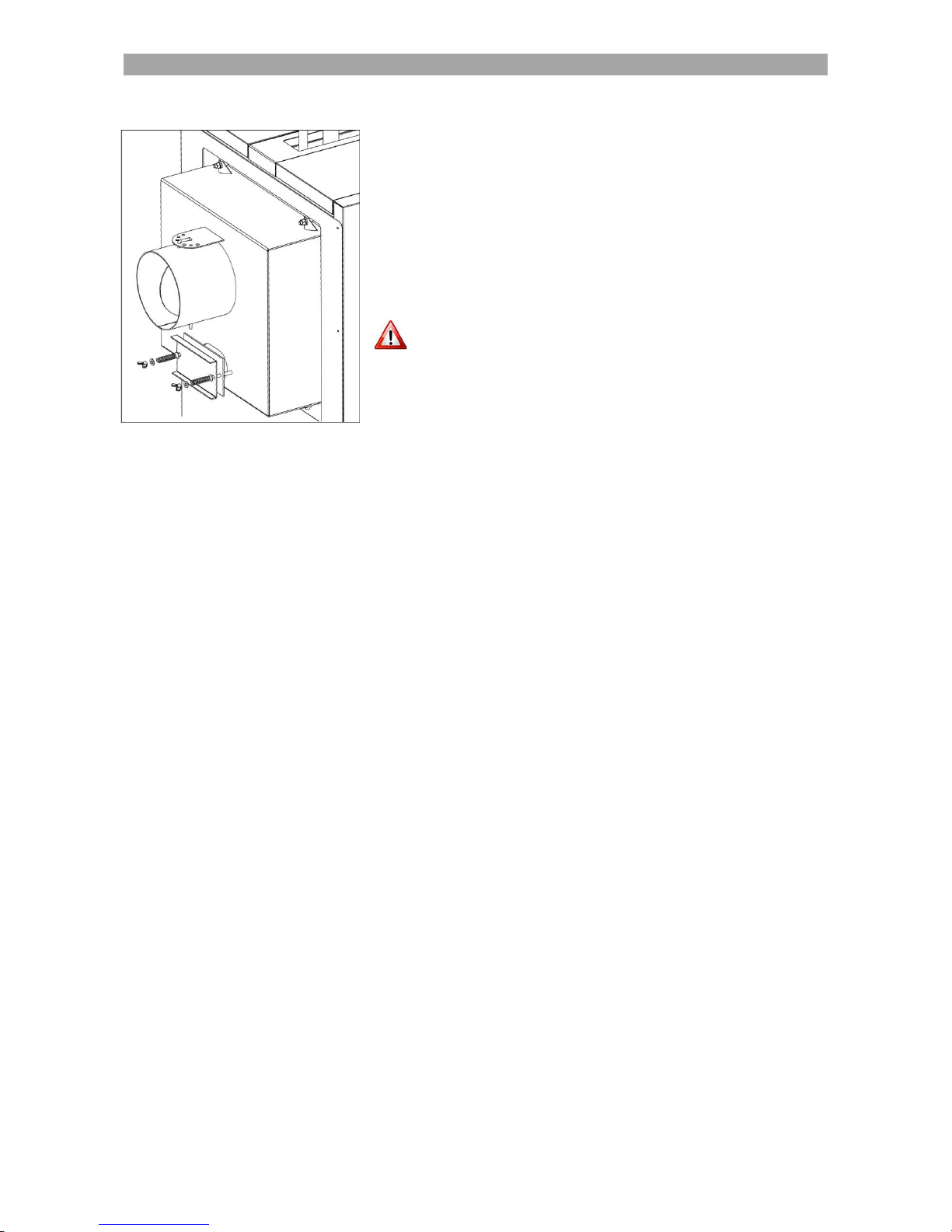
REMOVING THE UPPER AXIS
Remove the protection cover of the transmission system.
Remove the two gears from the axes by unscrewing the headless inserted screws keeping
them in place. You do not need to unmake the chain! Remove them all together with
the chain.
Unscrew the four nuts from the back side of the flange (see Fig 10).
Remove the whole feeder together with the bearings and supporting disk (see 0).
Fig 10. Removing the upper axis flange
When putting back together, it is absolutely necessary to put the rubber gasket at its
position!
Fig 11. Removing the upper axis
SERVICE AND MAINTENANCE
30
REMOVING THE LOWER AXIS
Remove the protection cover of the
transmission system.
Remove the two gears from the axes by
unscrewing the headless inserted screws keeping
them in place. You do not need to unmake the
chain! Remove them all together with the chain.
Unscrew the four nuts keeping the motor in
place and remove it (see Fig 12).
Remove the support disk and the feeder.
When putting back together, it is absolutely
necessary to put the rubber gasket at its position!
Fig 12. Removing the lower axis
7.5.3. Service after power blackout
In case there is a power blackout, it is absolutely necessary to perform some checks and take
some safety measures to avoid overheating. The solid fuel has all the time a certain amount of
fuel in the fire chamber, which will not stop burning immediately.
Turn the control panel to OFF.
When the power is restored, turn on the control panel and make sure all the devices function
properly.
7.5.4. Replacement of the ignition element
In case you need to replace the ignition element follow the instructions:
Turn OFF the control panel and disconnect from electricity.
Disconnect the connection wires of the ignition element from the control panel and loosen the
plastic tap holding them in place.
Remove the fan by unscrewing the four screws keeping it in place.
Remove the ignition element from the tube and insert in position the new one. Push the
ignition element to ensure it is positioned at the end of the tube.
Pull the cables of the ignition element through the provided hole, tighten the plastic tap and
connect the ignition element to the control panel.
Fig 13. Removing the ignition element

SERVICE AND MAINTENANCE
31
7.6. Maintenance after long stop
7.6.1. Maintenance of the boiler
It is necessary to perform a general maintenance and cleaning of the boiler after the heating
season. Clean thoroughly all the surfaces of the boiler as described in the corresponding
paragraph. Also clean the chimney box, and all the chimney parts where ash might be deposited.
After cleaning all the ash, empty the ash box and leave the boiler clean for the next winter
season.
After long stop of the boiler, before you put in function you need to perform the following checks:
Check the condition of the electric cables and the sensors. Make sure they are not damaged.
Check that the thermometer indicates the correct temperature and all the thermostats
function properly. Make sure the bulbs are properly positioned in the case.
Make a general check of the chimney and make sure it is clean and free of obstacles.
Verify the pressure in the heating network and the boiler.
Do not empty the water of the boiler and the heating installation after the heating
season! It will corrupt all the installation and especially the boiler.
Check that all the valves are working properly. Replace them if necessary. Pay special
attention so that all the safety equipment of the boiler functions properly!
Make sure all the ball valves of the boiler and other relative equipment are open.
Check the function of the pumps. They might be blocked after long stop.
Check that there have been no modifications to the installation and the boiler room
(ventilation openings, chimney, doors).
Check the fan and clean from dust. Turn it manually to ensure it is not blocked.
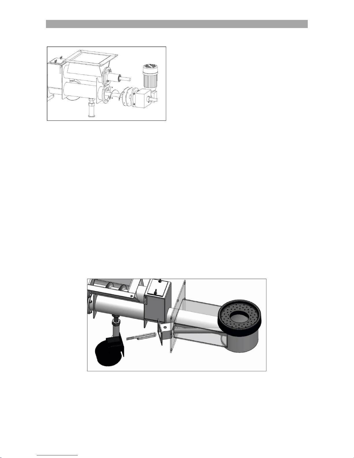
7.6.2. Maintenance of the furnace
It is necessary to perform a general maintenance and cleaning of the furnace after the heating
season. The maintenance of the furnace should only be done when the boiler is stopped, cool
and the power deactivated. For easier maintenance it is recommended to leave all the fuel in the
silo be consumed before you proceed to works. The maintenance procedure includes the
following steps:
Do not attempt to do any maintenance or service to the furnace while working!
There is serious danger of burning! Wait until the boiler is cool and deactivate
from the electricity.
Make sure the silo is empty. If not, empty manually the silo before proceeding to any works.
Open the silo cleaning door if necessary to remove any remaining fuel.
Remove the silo from the furnace body by unscrewing the bolts.
Remove the motoreducer which is mounted on the lower axis. See instruction in chapter
7.5.2.
Check the motoreducer. Check the oil level in the reducer and add oil if necessary.
Remove the two feeders. Check them and make sure they are in good shape and not
deformed.
Clean the tubes where the feeders are inserted. Remove any fuel or ash remains.
Remove the cast iron plate of the furnace.
Clean thoroughly the elbow underneath the plate, form where the fuel is provided. It is very
important to be clean of any obstacles that could block the feeding.
Clean very well all the holes on the plate surface. If they are blocked use a sharp tool to clean
them.
Put together all the pieces in the reverse order. Check all the sealing material between the
connections. Make sure they are in good shape and provide an air-tight sealing. Tighten well
the screws to ensure an air-tight connection.
After putting together the axes and the chain wheels, make the chain has a good grip on the
wheels and the rotation is performed freely. Grease carefully the chain and the wheels.
Attention: All the connections (boiler-furnace, furnace-silo, inspection doors,
etc.) must be air tight! If not there is high danger of backfire to the silo!

TROUBLESHOOTING
32
8. TROUBLESHOOTING
Problem
Cause
Solution
The lamps of the
control panel do not
light
- no electrical supply to the lamp
- the control panel is not
connected to electricity
- lamp defect
- electric cable defect
- check/replace the lamp
- connect to electricity
- check/replace the cables
The boiler does not
reach set
temperature
- fan blocked
- air passages are blocked
- boiler is not cleaned
- incorrect boiler start-up
- insufficient water in the system
- too big pump debit
- boiler under dimensioned
- bad quality fuel used
- insufficient chimney draught
- check/replace the fan, check the
function of the fan regulator and
thermostat
- clean the air passages
- clean the boiler
- start the boiler correctly
- fill the system
- regulate the pump speed
- change the fuel used
- check/clean the chimney
High temperature in
the boiler, but low
temperature at the
radiators
- too high hydraulic resistance in
the heating network
- thermostatic mixing valve is
connected wrong
- increase the pump speed
- check/replace the mixing valve
Condensation
formation in the fire
chamber
- too big boiler power
- too low return temperature in the
boiler
- fuel with excessive humidity
- load less fuel in the chamber
- install a return protection
system/thermostatic valve
- change the fuel used
Smoke coming out of
the doors
- boiler doors not regulated
- defect sealing cord of the door
- insufficient chimney draught
- too high air supply by the fan
- regulate the doors so that the
sealing cord stays tight
- check/replace the sealing cord
- check/clean the chimney
- reduce the air speed
The fan does not
function or it makes a
lot of noise
- set temperature reached
- disconnected by safety
thermostat
- capacitor/motor defect
- bad electrical connection of the
fan
- correct boiler function
- reset manually
- check/replace the fan
- check the electrical connection of
the fan

DECLARAȚIE DE CONFORMITATE EC
CE DECLARATION OF CONFORMITY
(conform cu ANEXA VII din Directiva Europeană 97/23/EC)
(in compliance with the Annex VII of the European Directive 97/23/EC)
Producător / The Manufacturer’s name: THERMOSTAHL ROMANIA SRL
Adresa producătorului / Manufacturer’s address: Str. Drumul Osiei 57-59, sector 6, București, România
PRIN PREZENTA, DECLARĂ
Declares that the equipment
Tip:
Type:
Cazan de apă caldă cu funcționare pe combustibil solid -încărcare automată
Heating boiler for solid fuel, automatically stocked
Obiectul declarației:
Object of the Declaration:
ECOBIO
Seria / Anul:
Serial Number / Year:
ESTE CORESPUNZĂTOR CU CERINȚELE DIRECTIVEI 97/23/EC-ECHIPAMENT SUB PRESIUNE
MEETS THE REQUIREMENTS PROVIDED BY THE 97/23/EC DIRECTIVE-PRESSURE EQUIPMENT
ȘI A URMĂTOARELOR DOCUMENTE:
AND THE REQUIREMENTS OF THE FOLLOWING DOCUMENTS:
Produsul este conform cu următoarele standarde:
The product is in compliance with the following standards:
EN 303-5:2012
Cazane de încălzit.
Partea 5: Cazane speciale care utilizează combustibili solizi, cu încărcare manuală şi automată, cu puterea utilă mai mică sau egală
cu 500 kW. Terminologie, cerinţe, încercare şi marcare
Heating boilers.
Part 5: Heating boilers for solid fuels, hand and automatically stocked, nominal heat output of up to 500 kW
Terminology, requirements,testing and marking
Directive Europene aplicabile echipamentului
European Directives applied to the equipment
97/23/EC
Directiva Echipament sub Presiune (HG 584/2004) / Pressure Equipment Directive (PED)
2014/35/EC
Directiva Echipamente de joasă tensiune / Low Voltage Directive (LVD)
2014/30/EC
Directiva Compatibilitate Electromagnetică / Electromagnetic Compatibility Directive (ECD)
Informații suplimentare / Additional information:
Toate echipamentele care fac obiectul prezentei declarații au fost testate hidraulic la presiunde de proba egală cu 1,5 ori presiune maxima de lucru, conform
cu Anexa I – p. 7.4 a Directivei 97/23/EC.
As provided by the Annex I - p. 7.4. of the 97/23/CE Directive, all the equipment object of the present Declaration have been hydraulic tested to a test pressure equal
to 1,5 times the maximum allowed working pressure.
Director General
General Director
România, București, 15 Octombrie 2015
Matsios Dionysios

THERMOSTAHL ROMANIA
HEATING SYSTEMS S.R.L.
DRUMUL OSIEI 57-59, sector 6
Bucharest 062395, Romania
www.thermostahl.ro
 Loading...