

PELLET BOILER
VERSION:
1.1
UPDATE:
31.05.2019
COMPACT
INSTALLATION AND USER MANUAL

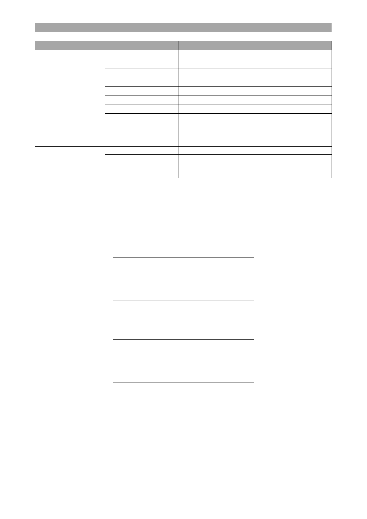
Contents
1. GENERAL INFORMATION ................................................................................... 3
1.1. Proper use of the appliance ................................................................................ 3
1.2. Safety warnings ................................................................................................ 3
1.3. Data label ........................................................................................................ 3
1.4. Document information ....................................................................................... 3
2. TECHNICAL FEATURES AND DIMENSIONS ......................................................... 4
2.1. Technical data .................................................................................................. 4
2.2. Pellet fuel ......................................................................................................... 4
3. BOILER MOUNTING ........................................................................................... 5
3.1. Transportation and delivery ................................................................................ 5
3.2. General requirements ........................................................................................ 5
3.3. Chimney .......................................................................................................... 6
3.4. Air intake ......................................................................................................... 7
4. INSTALLATION .................................................................................................. 8
4.1. Boiler connections ............................................................................................. 8
4.2. Return temperature protection ............................................................................ 9
4.3. Filling the system .............................................................................................. 9
4.4. Electrical connections......................................................................................... 9
5. CONTROLLER ................................................................................................... 10
5.1. General description ......................................................................................... 10
5.2. Operation functions ......................................................................................... 10
5.3. Menu functions ............................................................................................... 13
5.4. Error signals ................................................................................................... 16
6. BOILER START-UP ........................................................................................... 17
6.1. Initial lighting checks ....................................................................................... 17
6.2. Start-up of the boiler ....................................................................................... 17
7. BOILER STOP ................................................................................................... 18
8. SERVICE AND MAINTENANCE .......................................................................... 19
8.1. Cleaning the boiler .......................................................................................... 19
8.2. Maintenance intervals ...................................................................................... 19

GENERAL INFORMATION
1. GENERAL INFORMATION
1.1. Proper use of the appliance
Before you make use of this appliance make sure you have read and fully understood the
instructions included in this manual.
The installation and use of the appliance must be performed according to the instructions
indicated in this manual in combination with the current national safety regulations.
The appliance is designed for use in pumped hot water central heating systems. Any other use
is considered improper and is prohibited. THERMOSTAHL ROMANIA declines any responsibility
for damages or injuries caused by improper use; in this case the risk is completely at the user’s
responsibility.
To ensure an efficient and flawless function of the appliance, it is strongly recommended that
you have performed an annual service by a qualified technician.
1.2. Safety warnings
All installation and maintenance procedures must be carried out by professional and authorized
personnel, in compliance with the indications in the present manual and national regulations.
Any failure to correctly install this appliance could cause damage or injuries!
Do not make modifications to parts of the appliance, unless you have contacted the company
and an authorized service contractor.
Only original accessories and spare parts must be used to ensure correct and safe function.
Make sure you respect the cleaning and maintenance procedures on the corresponding intervals.
Failure to do so can cause malfunction to the appliance and possible damages.
The boiler is design to function on the fuels indicated in the corresponding paragraph. Any other
fuel is prohibited. Do not use explosive or flammable substances! Do not store such substances
inside the boiler room.
The working pressure varies according to the model. Make sure you use the appropriate water
pressure.
Working in a pressure higher than the one indicated in this manual is strictly
prohibited and dangerous!
1.3. Data label
The data label of the appliance is placed on the boiler’s back cover, on the external part. Make
sure that it is properly placed and readable.
On the label it is indicated the serial number and the manufacturing year of the appliance.
1.4. Document information
This document is an integral and indispensable part of the product and must be retained in good
condition by the user. Keep it in a safe place for future reference.
If the appliance is sold or transferred to another person, this manual has to always follow the
appliance and handed to the new user or installer.
3

TECHNICAL FEATURES AND DIMENSIONS
Boiler type
COMPACT 25
COMPACT 35
Nominal power1
kW
25
35
Global power (max-min)
kW
27,8-9,9
35,0-10,6
Pellet consumption (max-min)
kg/h
5,5-2,2
7,7-3,1
Efficiency (max-min)
%
94,5-93,0
94,5-93,0
Max working pressure
bar 3 3
Max working temperature
C
85
85
Exhaust gas temperature
C
160
160
Water contents
lit
28
40
Chimney diameter
mm
80
80
Air intake diameter
mm
60
60
Fuel tank
kg
55
70
Fuel autonomy
h
20
20
Weight (empty)
kg
175
200
Dimensions LxWxH
mm
860x590x1190
880x590x1355
Power consumption (max-min)
W
525-225
540-240
Electrical connections
V/Hz
230/50
230/50
Pellet fuel characteristics
Diameter
6-8 mm
Length
12-30,5 mm
Density
650-700 kg/m3
Ash content
<1%
Calorific power
>4,8 kWh/kg
Humidity content
<8%
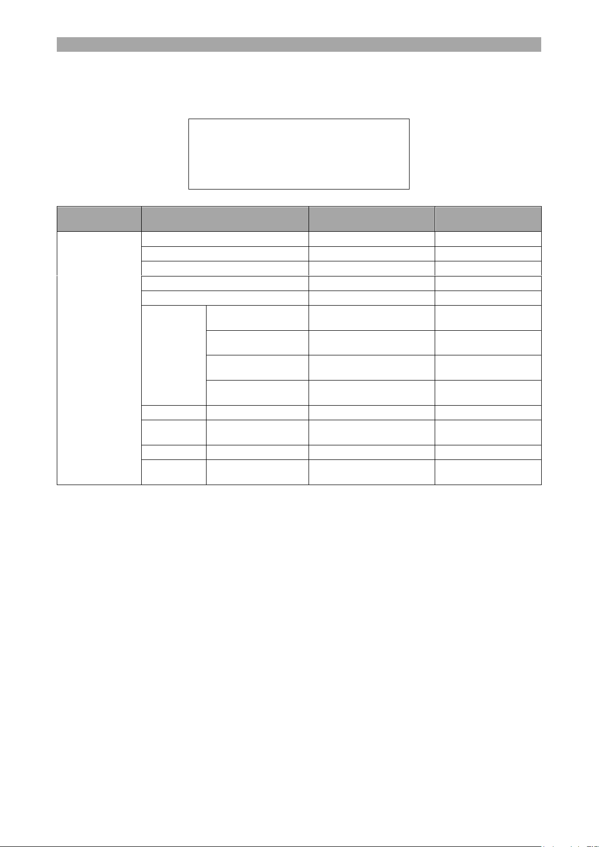
2. TECHNICAL FEATURES AND DIMENSIONS
2.1. Technical data
1. Nominal power output is obtained with fuel type C, calorific power 4,9 kWh/kg according to
standard EN 303-5:2012.
2.2. Pellet fuel
Pellet is used in an automatic way by means of an automatic pellet feeding mechanism. Only
wood pellets are to be used with this boiler. No other fuel is allowed to be used in the boiler. The
pellet is deposited in the fuel tank at the back of the boiler, and then automatically fed through
the feeder, which is controlled by the controller.
As fuel, it is recommended to use only premium quality wood pellet 6-8 mm diameter. Note that
if lower quality pellet is used, the ash produced can be signifantly bigger and the cleaning interval
more often. The pellet bags must be stored in a dry, not too cold environment.
Table 1. Pellet fuel characteristics
The quality of the pellets, calorific power, humidity and ash content is very
important for the boiler function and efficiency!
It is prohibited to manually feed pellets into the grate!
It is prohibited the use of processed wood pellets, or other chemical treatment.
It is prohibited the use of explosives, inflammable materials, plastic, domestic
residues, etc.
NEVER BURN ANY TYPE OF CORN, CHERRY PITS, STICKS OR OTHER TYPES OF FUEL
IN THE BURNER.
4

BOILER MOUNTING
3. BOILER MOUNTING
3.1. Transportation and delivery
The boiler is delivered on wood pallet. The loading and unloading of the boiler must be performed
with a forklift or a crane.
The boiler is very heavy. Do not try to lift by hands or other unsuitable
equipment. Danger of injury! Perform all moves with extreme caution.
Remove the boiler packaging with attention. Keep the packaging material away from
children since it can be dangerous. After having unpacked everything, make sure that the
appliance is intact and undamaged. In case of doubt do not use the appliance and inform the
supplier.
The COMPACT boiler is delivered with the following equipment:
Boiler steel body
Rockwool insulation mounted on the boiler body
Metal covers mounted on the boiler body
Incorporated pellet tank at the back of the boiler
Fuel feeder system
Pellet grate made of INOX steel
Ash box under the grate
Leveling supports
Electrical cable with plug
In the documentation folder you will find:
Technical manual
Warranty leaflet
3.2. General requirements
The boiler must be installed according to the applicable regulations as far as the chimney
installation and safety regulations are concerned. The installation should be performed only by
authorized personnel, and special care must be taken for the correct installation and draught of
the chimney.
The boiler must be placed on a horizontal plane, with adequate mechanical resistance to support
the boiler’s weight. The boiler can be installed in a special boiler room, or inside the house. The
installation must be performed in such a way so that it is easily accessible from all the sides.
The lack of draught from the chimney, or the obstruction of air intake can affect the correct
function of the product, cause error in the ignition, and even emit smoke.
The regular maintenance of the boiler must be performed at least once a year by an
authorized technician.
Special care must be taken for the air intake of the boiler, especially if the boiler is installed
in a narrow space.
Place a protective fireproof base (metal or ceramic) between the boiler and the floor,
especially if the floor is made of flammable material (wood, carpet).This board must be at
least 25-30 cm bigger in all directions than the dimensions of the boiler.
A safety distance is recommended between the sides of the boiler and walls, of at least 40
cm. This distance should be even bigger according to the objects close to the boiler (furniture,
curtains, decoration, etc.).
Make sure that the chimney remains clean and free of ash and obstacles at all times.
Pay attention so that the room temperature sensor positioned at the back of the boiler is not
close to the chimney.
Before every startup, or after an error or blackout, make sure that the grate is not full with
ash or pellet and the door is tightly closed.
After a fault startup, remove the unburnt pellet from the grate before you make a new startup.
5
BOILER MOUNTING
It is recommended to always keep clean the grate, in order to ensure long life and correct
ignition.
Do not ever use inflammable materials for manual ignition of the boiler!
Before any work of maintenance is effected, please turn off the boiler and disconnect from
electricity.
Do not open the boiler door during function!
Do not introduce any other materials for combustion in the pellet tank, or manually
in the grate, other than wood pellets!
3.3. Chimney
The chimney installation must supply sufficient draught, air tightness and protection against
condensation.
The appropriate chimney installation is very important for the boiler’s efficient
and safe function!
The chimney must be vertical, with no changes in the direction. The cross-section of the chimney
can be round or rectangular. If the chimney is installed in the exterior, it must be insulated. The
cross-section and total height of the chimney must be correctly calculated to ensure natural
draught.
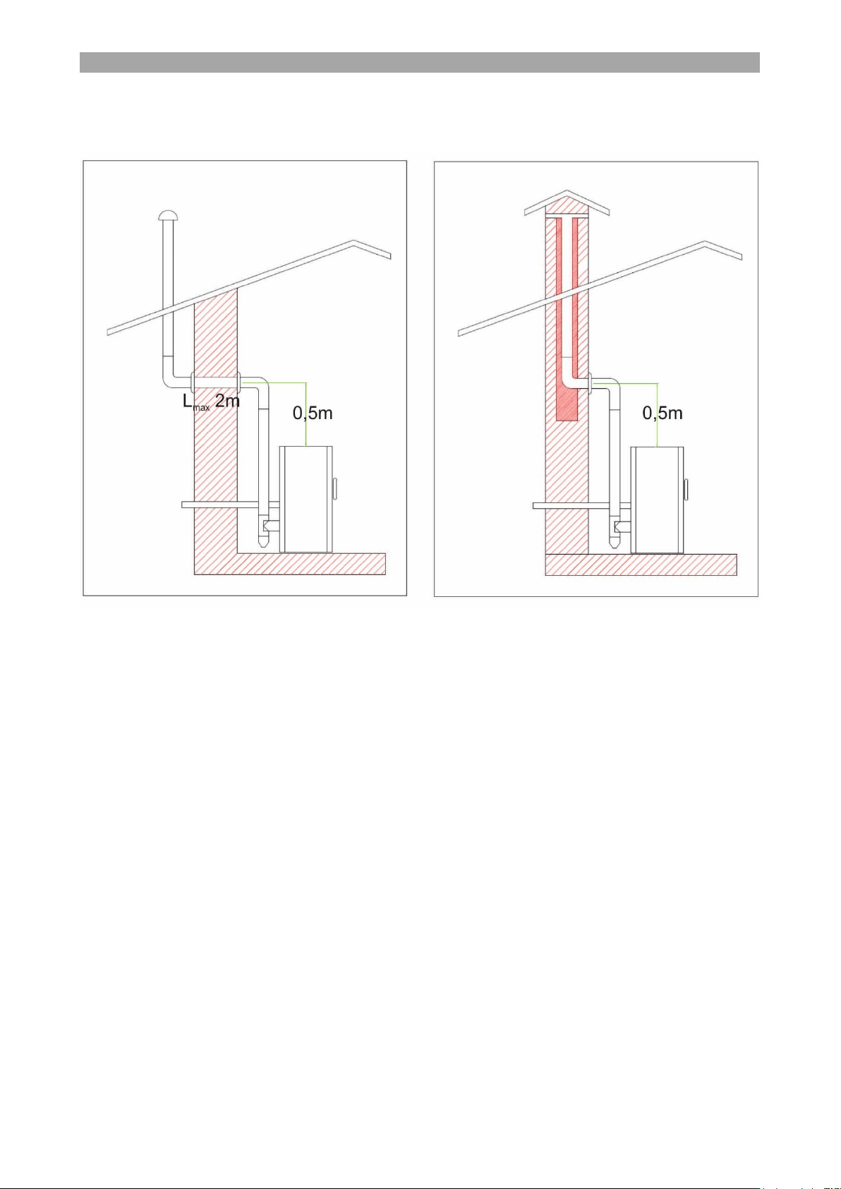
The horizontal part connecting the boiler’s chimney pipe with the vertical chimney must have
maximum length 2 m. If this distance is bigger, it is recommended to have a 15-30o inclination
upwards. The connection with the boiler’s chimney pipe must be air-tight. If the total route of
the chimney pipe is more than 10 m, it is recommended to use a 100 mm chimney pipe.
It is prohibited to change the exhaust diameter by any means or reduction
between the boiler outlet and the vertical chimney pipe!
The chimney must be equipped with a cleaning door at its base. Also cleaning doors are
recommended where there are changes in direction and ash can be accumulated. Tactical
cleaning is recommended (every 3 months) for efficient boiler function.
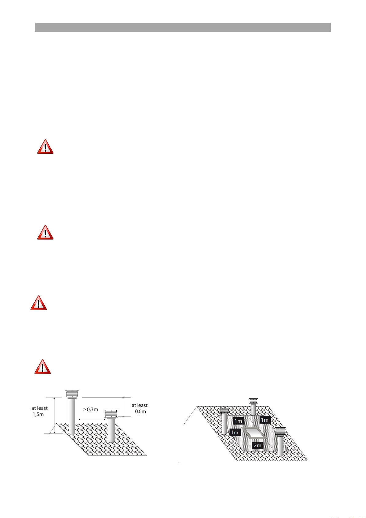
A chimney terminal must be installed at the end of the chimney for protection against weather
effects and foreign objects entrance. In areas with strong winds a special anti-downdraught
terminal is recommended.
The chimney terminal must always be installed perpendicular to ground!
The chimney height must exceed the roofline by at least 1 m. If there are other obstacles
positioned on the roof, the chimney height must exceed them by at least 1 m. If there are
multiple chimneys, minimum distance between them is 0,3m.
Each boiler should be connected to an independent chimney. Connection of multiple
boilers to the same chimney is not recommended.
It is prohibited to use as a chimney flexible aluminum tube!
Fig 2. Chimney distances
6
BOILER MOUNTING
The vertical chimney pipe can be installed partially inside as in Fig 3, with a maximum of two
90o elbows. The vertical chimney pipe must have a height of minimum 2 m. All chimney
connections must be sealed with a temperature resistant silicon gasket.
Fig 3. Chimney connection
3.4. Air intake
The necessary for combustion air intake of the boiler is absorbed externally through an air intake
pipe that must be installed, as seen above. The air intake pipe must be protected with a grate,
according to UNI 10683.
The air intake can also be absorbed from the installation space. In this case, special care must
be taken so that sufficient air supply is given to the installation room by means of air intakes
surfaces, which must be protected with a grate, according to UNI 10683.
Periodically, the air intake pipes must be controlled against blocking.
7

INSTALLATION
Legend
1
Outlet
2
Return
3
Chimney pipe
4
Air intake pipe
5
Room temperature sensor
6
External thermostat connection (THERM)
7
Service programmer connection (JA)
8
General ON/OFF switch and electrical connection
9
STB overheating thermostat
4. INSTALLATION
4.1. Boiler connections
The boiler comes preassembled with all necessary for function hydraulic components (pump,
expansion vessel, safety valve, air-relief valve). All connections are performed at the back of the
boiler. There are two side doors for access inside the hydraulic of components of the boiler.
The boiler is intended for maximum working temperature 85oC and maximum pressure 3 bar.
Safety valve is not installed inside the boiler, it must be installed externally and
connected to the drainage!
External thermostat connection must be simple electrical switch (ON/OFF).
Voltage feed in these terminals can destroy the controller!
8
INSTALLATION
4.2. Return temperature protection
For the correct function of the boiler and for protection against corrosion it is very important to
ensure steady temperature at the return of the boiler of at least 55oC.
This can be ensured by installing a recirculation pump between the boiler outlet and return (see
connection diagrams).
An alternative variation is by installing at the return of the boiler a three-way thermostatic valve.
Having a return temperature less than 55oC is very dangerous for the boiler longlife and can cause warranty loss!
4.3. Filling the system
After completing all the hydraulic connections, the circuit may be filled with water. After filling
the system, open the radiators air valves to get rid of the air in the installation.
Verify that the installation pressure is according to the technical features of the boiler. A
manometer should be installed on the cold water inlet to verify the cold pressure, at the lowest
point of the installation, at a point close to the boiler.
The whole installation must remain under nominal pressure for at least 10 minutes. During this
period, check that all the connections are tight and there are no water leakages. Make sure that
during this period no pressure drop appears.
After firing the boiler, make sure the network functions properly at working temperature and
pressure.
The hardness of the mains water supply affects the boiler’s life span. It is
recommended to use a water softener if water hardness exceeds 15of.
Do not fill the system at the working pressure! When the boiler will be heated,
the water pressure will raise. Filling pressure must be at least 1 bar lower than
working pressure!
4.4. Electrical connections
The electrical connection is performed by the given cable. Plug the one end at the IEC plug at
the back of the boiler, and the other end to a 230V plug. The plug where the boiler will be
connected must have grounding, and must be ensured that has tension in nominal parameters.
The plug on the boiler is protected with an incorporated electrical fuse and has a general electrical
switch ON/OFF.
Make sure that the electric cable is not in contact with hot parts of the boiler or the chimney,
and is not crushed by heavy parts.
THERMOSTAHL ROMANIA SRL declines any liability for damage caused to
people, animals and goods, due to defects caused by faulty electrical
connections or lack of connecting the boiler to an efficient grounding system.
9

CONTROLLER
Button
Function
MODE / ESC
1
Mode selection (Manual, Auto) / Keep pressed to exit
-
2
Value decrease / menu navigation
MENU / OK
3
Menu enter / Setting confirmation
+
4
Value increase / menu navigation
5
Controller ON/OFF button / exit to main menu
IR
Remote control receiver
D
Display
2 2 .0
°C
1 1 1 4 6 5 .0
°C H 2 O
1 1 1 4
T H E R M O S T A H L
< T i p p r o d u s >
P r e s s M e n u 2 8 .0
°C H 2 O 1 1 1
4
F i r e : 5 T e r m : C O F F
5. CONTROLLER
5.1. General description
Description of buttons
5.2. Operation functions
After switching the boiler on from the main switch at back side, press the controller ON/OFF
button to activate the controller. The following messages will appear on the display on sequence:
10
CONTROLLER
FUNCTION
DISPLAY MESSAGE
DESCRIPTION
Function menu
Manu
Manual mode
Auto
Auto mode
Eco activated
Eco mode
Boiler status
IGNITION
Ingition mode
ON
Normal operation
SHUTDOWN
Fire off mode
OFF
Device stopped
STOP AFTER
BLACKOUT
Device stop after electric blackout
IGNITION AFTER
BLACKOUT
Ignition mode after electric blackout
Chronothermostat
Chrono programmer
Chronothermostat programming activated
Sleep 12:30
Slepp mode activated
Error
Error**
Automatic error recognition
ALARM
Alarm activated, boiler stopped
M o d e A U T O M e n u
T e m p 2 3
°C F a n A
e s c 2 3
°C O k
- T e m p e r . +
By pressing the MODE button the boiler can be changed to one of the available function modes:
manual mode (MANU), automatic (AUTO), economic (ECO).
5.2.1. AUTO mode
In mode AUTO, the boiler will automatically adjust the power level according to the temperature
settings chosen and the signal from the room temperature sensor (if activated). If the room
thermostat contact is open, the boiler will go to minimum power, but will not shut down.
In AUTO mode on the display will appear the following message:
By pressing the Button 2 (-) the room temperature can be adjusted from 5 to 35oC. By keeping
pressed the Button 2 (-), the following message will appear on the display and the same setting
can be adjusted here through the Buttons 2 (-) and 4 (+):
If the room temperature sensor is deactivated, the message Temp 0 will be shown instead, the
set point for mode AUTO will be the water temperature selected, and the room temperature
sensor will behave as an ON/OFF signal.
By pressing the Button 4 (+) the power level can be adjusted.
11
CONTROLLER
M o d e M A N U M e n u
F i r e 2 3
°C F a n A
e s c O k
- F i r e +
M o d e E C O M e n u
T e m p 2 3
°C F a n A
e s c 2 3
°C O k
- T e m p e r . +
5.2.2. MANUAL mode
In mode MANU, the power level of the boiler can be manually selected. The room thermostat
doe not function in this mode. In MANU mode on the display will appear the following
message:
By pressing the Button 2 (-) power level can be adjusted from Fire 1 to Fire 5. By keeping
pressed the Button 2 (-), the following message will appear on the display and the same setting
can be adjusted here through the Buttons 2 (-) and 4 (+):
The use of MANUAL mode is restricted for service settings and should not be
used in normal operation.
5.2.3. ECO mode (recommended)
In mode ECO, the power level of the boiler can be manually selected. If the room thermostat
contact is open, the boiler will go to minimum power, and will shut down after a preset
time. In ECO mode on the display will appear the following message:
By pressing the Button 2 (-) the room temperature can be adjusted from 5 to 35oC. By keeping
pressed the Button 2 (-), the following message will appear on the display and the same setting
can be adjusted here through the Buttons 2 (-) and 4 (+):
If the room temperature sensor is deactivated, the message Temp 0 will be shown instead, the
set point for mode ECO will be the water temperature selected, and the room temperature sensor
will behave as an ON/OFF signal.
By pressing the Button 4 (+) the power level can be adjusted.
12

CONTROLLER
MENU
PARAMETER
VALUE RANGE
RECOMMENDED
SETTING
Water temp.
Heating temp.
40-85oC
65-75oC
Sanitary temp.
30-65oC
45oC
MENU
PARAMETER
VALUE RANGE
Date & Time
Time
00–23
Minutes
0–59
Day
Mo-Tu-We-Th-Fr-Sa-Su
Day Number
1–31
Month
1–12
Year
2010-2109
e s c S e t
< W a t e r T e m p . >
e s c S e t
< D a t e & T i m e >
5.3. Menu functions
By pressing the Button 3 (MENU/OK) the different menu windows can be cyclically navigated.
There are 5 main menu windows, in order to access the parameters of a menu, press the Button
3 (MENU/OK).
In order to modify a parameter, press the Button 3 (MENU/OK) with indication Set. At this
point, the indication will change to OK, and the chosen parameter will blink. Change the value
through the Buttons 2 (-) and 4 (+). Confirm the value by pressing the Button 3 (MENU/OK).
After setting the value, use the Buttons 2 (-) and 4 (+) to navigate to the next parameter.
Press the Button 1 (MODE/ESC) at any point to go up a menu level. Press the Button 5
(ON/OFF) at any point to exit to the main window.
5.3.1. Water temperature
The water temperature for heating and sanitary mode can be set at this menu. On the display
the following message will appear:
5.3.2. Date and time
The date and time can be set at this menu. On the display the following message will appear:
5.3.3. Chronothermostat
In this menu, the user can set 6 different programs for each individual day of the week, this
meaning that there is a total available of 6*7=42 programs. On the display the following
message will appear:
13

CONTROLLER
MENU
PARAMETER
VALUE RANGE
RECOMMENDED
SETTING
Chrono
Enable
On / Off
Accordingly
Load Profile
1-10
1
Reset Chrono
Confirm?
Ok
Prog. 1-6
for each
individual
day
P1 Enable
On / Off
Accordingly
P1 Start
00.00-23.59 / Off
Accordingly
P1 Stop
00.00-23.59 / Off
Accordingly
P1 Air Temp.
5-35oC
18-25oC
P1 Heat Temp.
40-85oC
60-80oC
P1 Fire
1-5
Accordingly
P1 Days
Mo-Tu-We-Th-Fr-
Sa-Su
e s c S e t
< C h r o n o >
e s c o f f S e t
< S l e e p >
After activating the chronothermostat, the user can choose the individual settings for every
program and day of the week. The Reset parameter will null all the settings of the current
program.
For every program the start time and stop time of the boiler can be set from the corresponding
parameters P1 Start and P1 Stop, as well as the air temperature, water temperature, and power
level settings for this time interval.
Finally, with the P1 day parameter the day of the week when this program will be applicable can
be chosen.
After completing the P1 program, the same procedure is used to set P2-6 programs.
Pay attention during the weekly programming, so that different settings do not
interfere for same day and time intervals.
5.3.4. Sleep mode
This option is available only while the device is activated and is in ignition or function mode. In
this menu, the user can set the automatic stop of the boiler at a certain time. On the display the
following message will appear:
Use the Buttons 2 (-) and 4 (+) to set the stop time of the boiler and the Button 3
(MENU/OK) to save this option.
14
CONTROLLER
MENU
PARAMETER
VALUE RANGE
RECOMMENDED
SETTING
Settings
Language
En-It-Fr-Es-Gr
En
Eco
On / Off
On
Back Light
01-1000 s
Accordingly
Tones
On / Off
On
o
C / oF / Auto
o
C / oF
o
C
Recipe
Pellet Temp.
States
-5...+5
0
Pellet Power
States
-5...+5
0
Air Flow Temp.
States
-10...+10
0
Air Flow Power
States
-10...+10
0
Thermosat
Activation
On / Off
Accordingly
Charge
Pellets
Activation
Ok
Cleaning
Activation
Ok
Start
Pump
Activation
Ok
e s c S e t
< S e t t i n g s >
5.3.5. Settings
In this menu, the user can make general configuration settings of the device. On the display the
following message will appear:
The Eco parameter activates or deactivates the Eco mode.
The Back Light parameter sets the permanent lighting of the display (On) or for a certain amount
of time after pressing a button (01-1000 s).
The tones parameter will enable the keyboard sound when pressing a button.
Through the Recipe parameters, the pellet feeding and air supply can be adjusted individually
for the ignition mode (Temp. States) and the function mode (Power States). For every unit
interval, a 2,5% modification is performed to all the power levels.
Through the Thermostat parameter, the integrated room temperature sensor can be activated
(On) or deactivated (Off).
The last three parameters are used to manually activate the individual devices (feeder,
cleaning motor, pump), and must be used only during service by authorized technician.
15

CONTROLLER
CODE
MESSAGE
SOLUTION
A01
Failed ignition
Clean the grate from pellets and retry igntition
A02
No flame
Fill the tank with pellets
A03
Tank overheating
Check the fuel tank temperature sensor
A04
Exhaust temperature alarm
Check the exhaust temperature sensor and the
combustion settings
A05
Chimney block
Check the chimney condition, clean from ash and
possible obstacles
A06
Insufficient combustion air
Clean the grate, the air intake, the chimney
A07
Open door
Make sure the door is closed
A08
Exhaust fan damage
Call service
A09
Exhaust temperature damage
Call service
A10
Ignitor damage
Call service
A11
Pellet feed damage
Call service
A13
Controller damage
Call service
A15
Pellet level alarm
Check the fuel level in the tank
A16
Water pressure
Assure correct pressure of the installation
A18
Water temperature overheating
Investigate the causes of overheating
MESSAGE
DESCRIPTION
Service
Call the service for regular maintenance
Ex. temperature sensor error
The exhaust temperature sensor is damaged
Water temperature sensor error
The boiler water temperature sensor is damaged
Water pressure sensor error
The water pressure sensor is damaged
Water pressure out of limits
The water pressure in the heating installation is out of
limits
e s c S e t
< E r r o r >
i n f o A L A R M A 0 1
<
Alarm description
>
5.4. Error signals
The controller automatically recognizes the corresponding error, and will inform the user by
displaying the corresponding error code on the display. The errors are divided in two categories:
5.4.1. Errors
Errors are minor importance faults during operation. By pressing the Button 3 (MENU/OK),
the description of the error appears on the display. These minor errors do not stop the function
of the boiler. When an error incures, the following message will appear on the display:
5.4.2. Alarms
An alarm will be activated when a major safety issue will incure. When an alarm incures, the
ALARM message will blink on the display, and an alarm code and description will appear. The
following message will appear on the display:
By pressing the Button 1 (MODE/ESC), an indication of the alarm cause will appear, according
to the following table:
16

BOILER START-UP
2 2 .0
°C 1 1 1
4
I G N I T I O N
6. BOILER START-UP
6.1. Initial lighting checks
Before you start the boiler, make the following checks:
Check all the hydraulic connections and make sure they are tight. Make sure there is no
leakage or moisture on the pipes or other equipment.
Make sure that the connection with the chimney is air-tight and the chimney installation is
properly made.
Make sure that the pressure in the network is correct.
Check that the boiler pump functions properly.
Make sure the boiler’s separation valves are open.
Make sure that there is sufficient air supply and natural ventilation in the room.
Make sure there is pellet in the pellet tank.
Do not store inflammable materials or fuel close to the boiler! Before you light
the boiler make sure the room is clear and safe.
6.2. Start-up of the boiler
6.2.1. Manual start-up
Keep pressed the Button 5 (ON/OFF) for 2 seconds until the message IGNITION will appear
on the display.
6.2.2. Start-up by the room temperature sensor
The boiler will automatically start when the room temperature value is below the set limit. This
mode will be enabled only if the room temperature sensor is activated (see paragraph 5.3.5),
the AUTO or ECO mode is chosen, and the boiler is activated by the main electrical switch.
6.2.3. Start-up by the chronothermostat
The boiler will automatically start according to the chronothermostat settings (see paragraph 0),
given that the AUTO or ECO mode is chosen and the boiler is activated by the main electrical
switch.
6.2.4. Start-up by external room thermostat
The boiler will automatically start when signaled from an external room thermostat. This requires
an external room thermostat to be connected to the corresponding terminals setting s (see
paragraph 4.1), given that the AUTO or ECO mode is chosen and the boiler is activated by the
main electrical switch.
17
BOILER STOP
2 2 .0
°C 1 1 1
4
S T O P
7. BOILER STOP
7.1.1. Manual stop
Keep pressed the Button 5 (ON/OFF) for 2 seconds until the message STOP will appear on the
display.
7.1.2. Stop by the room temperature sensor
The boiler will automatically stop when the room temperature value has reached the set limit.
This mode will be enabled only if the room temperature sensor is activated (see paragraph
5.3.5), the AUTO or ECO mode is chosen, and the boiler is activated by the main electrical switch.
7.1.3. Stop by the chronothermostat
The boiler will automatically stop according to the chronothermostat settings (see paragraph 0),
given that the AUTO or ECO mode is chosen and the boiler is activated by the main electrical
switch.
7.1.4. Stop by SLEEP mode
The boiler will automatically stop according to the SLEEP mode settings (see paragraph 5.3.4).
The Sleep mode has priority over other settings made in the Chronothermostat menu.
7.1.5. Stop by external room thermostat
The boiler will automatically stop when signaled from an external room thermostat. This requires
an external room thermostat to be connected to the corresponding terminals settings (see
paragraph 4.1), given that the AUTO or ECO mode is chosen, and the boiler is activated by the
main electrical switch.
Do not stop the boiler by means of the main electrical switch ON/OFF! This can
cause damage to the boiler and may lead to alarm signals.
18

SERVICE AND MAINTENANCE
8. SERVICE AND MAINTENANCE
8.1. Cleaning the boiler
Solid fuel boilers require regular cleaning in order to function properly and efficient. Cleaning
must be effected at least once a week.
The boiler function must be stopped before cleaning! Make sure all the devices
are stopped, and the boiler has cooled down. It is strictly prohibited to clean the
boiler while in function!
8.2. Maintenance intervals
8.2.1. Daily maintenance
The pressure of the network must be daily verified to be within the allowed limits. Make sure
that all the safety devices and pumps function properly.
8.2.2. Weekly maintenance
The boiler and the burner must be cleaned every 3-4 days or at least once a week, depending
on the ash quantity accumulated. The ashes are collected to the ash box positioned under the
grate. Check regularly the quantity of ash accumulated in the ash box.
In order to clean the heat exchanger, open the external door cover and use the lever provided.
Push down firmly 3-5 times.
in order to clean the ash, open the external door cover
and the internal boiler door. Scrape the ashes from all
the surfaces. Empty the ashes from the grate and make
sure all the holes are clear of ashes and other obstacles.
The cleaning of the grate and the ash box can be made
also by means of a special vacuum cleaner.
All cleaning works should be done when
boiler is stopped and cooled!
8.2.3. Periodical maintenance
A periodical maintenance should be effected by an authorized technician. The frequency of this
maintenance depends on pellet quality, function time, chimney installation.
Call the service whenever the message Service appears on the display for periodical
maintenance, or there are difficulties on the boiler function.
8.2.4. Annual maintenance
It is obligatory that an annual maintenance is effected by an authorized technician. This includes
a general cleaning of the boiler and the heat exchanger, as well as a control of the electrical and
mechanical parts and all the safety equipment of the boiler.
Check the doors and the sealing cord. Make sure the contact with the boiler is air-tight. If ash
has accumulated on the sealing cord, clean it.
Empty the pellet tank to avoid moisture accumulation that can lead to wet pellets and feeder
blockage.
19

THERMOSTAHL ROMANIA
HEATING SYSTEMS S.R.L.
DRUMUL OSIEI 57-59, sector 6
Bucharest 062395, Romania
www.thermostahl.ro
20
 Loading...