

Thermo Solar ECO2 160, ECO2 200, ECO2 250, ECO2 300 Technical Installation Manual

TABLE OF CONTENTS
INSTRUCTIONS FOR THE MOUNTING
OF THE SUPPORT BASE ON TILT ROOF Page 4-5
DESCRIPTION OF THE PLUMBING ASSEMBLY BETWEEN THE WATER TANK
AND COLLECTOR ON TILT ROOF Page 6-7
INSTRUCTIONS FOR THE MOUNTING
OF THE SUPPORT BASE ON FLAT ROOF Page 8-9
DESCRIPTION OF THE PLUMBING ASSEMBLY BETWEEN THE WATER TANK
AND COLLECTOR ON FLAT ROOF Page 10-11
INSTRUCTIONS FOR THE MOUNTING
OF THE SOLAR SYSTEM ON FLAT ROOF Page 12-13
TECHNICAL CHARACTERISTICS – DIMENSIONS –
WEIGHTS OF SOLAR SYSTEMS Page 14
TYPES OF SOLAR SYSTEMS / PROPORTION OF ANTIFREEZE LIQUID – WATER Page 14
TECHNICAL CHARACTERISTICS OF THE WATER TANK Page 15
TECHNICAL CHARACTERISTICS OF THE COLLECTOR Page 15
ELECTRICAL CONNECTION DIAGRAM
OF AUXILIARY HEATING RESISTANCE (DOUBLE ENERGY) Page 16
ELECTRICAL CONNECTION DIAGRAM OF AUXILIARY HEATING RESISTANCE
AND COPPER TUBE COIL FOR EXTERNAL THERMAL SOURCE (TRIPLE ENERGY)
ORIENTATION OF SOLAR SYSTEM Page 17
INSTALLATION OF 6 SOLAR SYSTEMS ON LINE
DIMENSIONS OF SOLAR SYSTEMS Page 18
INSTALLATION OF SOLAR COLLECTORS ON LINE (20sq.m.) Page 19
TECHNICAL INSTALLATION
MANUAL FOR THE
SOLAR SYSTEM
TABLE OF CONTENTS
INSTRUCTIONS FOR THE MOUNTING
OF THE SUPPORT BASE ON TILT ROOF Page 4-5
DESCRIPTION OF THE PLUMBING ASSEMBLY BETWEEN THE WATER TANK
AND COLLECTOR ON TILT ROOF Page 6-7
INSTRUCTIONS FOR THE MOUNTING
OF THE SUPPORT BASE ON FLAT ROOF Page 8-9
DESCRIPTION OF THE PLUMBING ASSEMBLY BETWEEN THE WATER TANK
AND COLLECTOR ON FLAT ROOF Page 10-11
INSTRUCTIONS FOR THE MOUNTING
OF THE SOLAR SYSTEM ON FLAT ROOF Page 12-13
TECHNICAL CHARACTERISTICS – DIMENSIONS –
WEIGHTS OF SOLAR SYSTEMS Page 14
TYPES OF SOLAR SYSTEMS / PROPORTION OF ANTIFREEZE LIQUID – WATER Page 14
TECHNICAL CHARACTERISTICS OF THE WATER TANK Page 15
TECHNICAL CHARACTERISTICS OF THE COLLECTOR Page 15
ELECTRICAL CONNECTION DIAGRAM
OF AUXILIARY HEATING RESISTANCE (DOUBLE ENERGY) Page 16
TECHNICAL INSTALLATION
MANUAL FOR THE
SOLAR SYSTEM
18
19
20
21
22-23
16-17
Page
PageCOLLECTOR’S DATA SHEET
TRANSPORTATION AND HANDLING

04
We first check that the height of the pitch roof from the
highest top until the lower part of the solar system is at
least 3800mm-minimum.
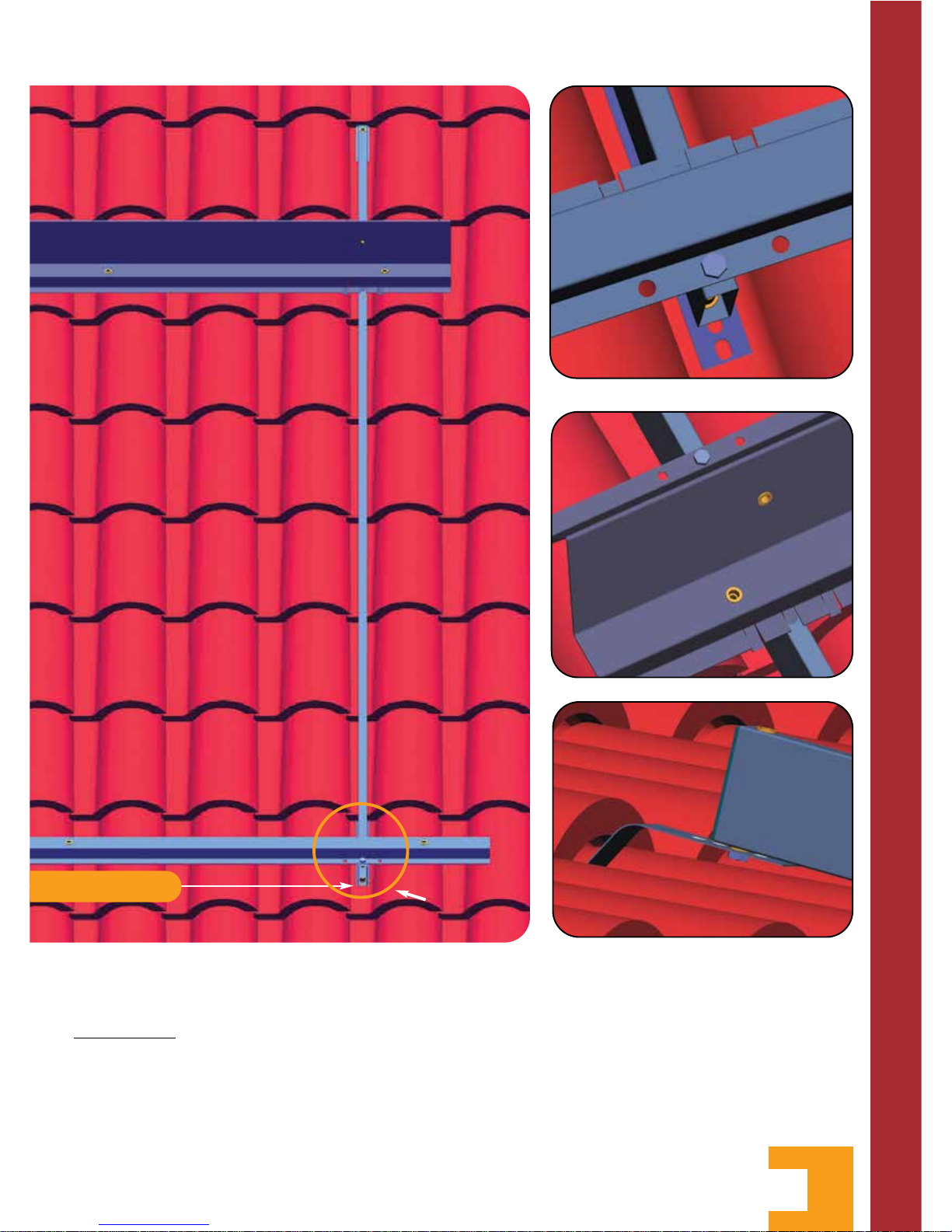
We begin from the lower part of the support base by
raising the tiles and positioning the stainless steel
straps (F) between and under the convex of tiles with a
distance between them of a min. 900mm and max.
1080mm (D1-D2).
We screw the stainless steel straps to the oblong wood
or flooring as at (photo 1) and we leave the one side
out of the tiles, at least 200mm
in the same distance
and length between them.
We reposition again the tiles as they were and we
screw the external side of the stainless steel straps (F)
on the vertical long bracket supports (A-A) of the
support base (photo 2) with the plastic hatch on the
min 900mm -
3.800 mm minimum
A
F
A
A
B
DÅ
photo 1
photo 2
photo 3
INSTRUCTIONS FOR THE MOUNTING OF THE
05
top side (photo 3)
We repeat the same process on the upper side of the
support base with the difference that:
ATTENTION:
We first screw the stainless steel
straps (F) on the top of the vertical long bracket
supports (A-A) as at (photo 6) after we have raised
the tiles, then we screw the stainless steel straps (F) to
the oblong wood or flooring as at (photo 1) and we
reposition again the tiles as they were before.
When we have finished with the vertical long bracket
supports (A-A) we position and screw at their lower
part the horizontal support angle (C) of collector as at
(photo 4) and at their upper part the horizontal
support angle (B) of water tank-collector (photo 5 ).
SUPPORT BASE ON TILT ROOF
C
B
A
A
C
DÇ
photo 4
photo 5
photo 6

01
02
03
04
05
06
07
09
10
11
12
13
14
15
13
17
24
14
13
18
13
15
16
13
15
02
06
DESCRIPTION OF THE PLUMBING ASSEMBLY BETWEEN THE
 Loading...