

Page 1
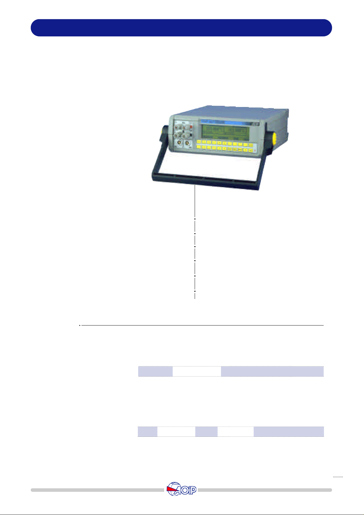
high precision thermometer
PHP 601
Resolution 0.001°C
Main applications include:
• Temperature measurements using RTDs and/or
thermocouples
• Absolute or differential measurements over two
channels.
• Differential thermal analysis.
• Checking the temperature stability of furnaces or
baths.
• Monitoring (alarm) and temperature recording.
functions
The PHP 601 is a high accuracy, dual
input thermometer suitable for use with
RTDs (e.g.: Pt 100) and thermocouples.
The PHP 601 is capable of storing sensor
characteristics and coefficients and can
scan up to 12 sensors using the model
SHP 101 Scanner.
Its main applications include the calibration of temperature sensors. By using our
CAL'EXPERT software to drive the
PHP 601 thermometer, scanner and a thermal device such as temperature bath, dry
block calibrator or oven, a complete calibration procedure can be performed,
reports generated and certificates printed
for individual sensors.
Accuracy 0.005°C
Self-contained
RTDs and thermocouples
Dual inputs
RS 232 or IEEE 488 interfaces
Resistance measurement (1) ..................................................................................
Accuracy (2)
All ranges Stability 24 hours
25 to 3 200 Ω 0.0005%Cal 0.0015% + 0.0005% 0.0030% + 0.0005%
(1) 4 wire configuration, all currents. For the 3 wire configuration, add 1mΩ.
(2) Accuracy is expressed in ± (% reading + % range) at 23°C ± 1°C.
DC voltage measurement .......................................................................................
M e a s u re m e n t
R a n g e
100 mV - 50 to + 117.5 mV 0.2 µV 0.001% + 0.4 µV 0.004% + 0.6 µV 0.008% + 0.8 µV
r a n g e R e s o l u t i o n Stability 24 hours
90 days 1 year
Accuracy (1)
90 days 1 year
(1) Accuracy is expressed in ± (% reading + nV) at 23°C ± 1°C.
Temperature coefficient ≤ 10% of accuracy/°C over 90 days.
1
Page 2

Temperature measurement.....................................................................................
Direct reading in mV or °C, °F or K.
- From 1 to 4 calibration points may be
entered for all types of sensors.
- Digital filter.
- Programming using either the RS 232
link (standard) or the IEEE 488 link
- Direct control of the SHP 101 scanner.
- Storage of up to 5000 measurements
together with date.
- Measurements triggered by internal or
external event.
- 2 alarm outputs relays.
(option).
RTD measurement.................................................................................................
Measurement of all types of sensors as
described below:
- Standardized sensors according to IEC
- EIT 90 equations defined by R at 0.01°C
and the deviation function coefficients or
by resistance values at fixed points.
Publication 751/1995,
α = 3851, Pt 100, 200, 500 and 1000.
JISC 1604/1989, a = 3912, JPt 100.
- Polynomial equations defined per point
(25 points max.).
EIT 90, α = 3926, Pt 100.
DIN 43760, α = 618, Ni 100.
MIL-T 24388C, α = 672, Ni 120.
MINCO 16/9, α = 427, Cu 10.
For sensors not complying to the
International Temperature Scale (ITS 90)
correction of the deviation ITS 90-IPTS 68,
1993 is applied.
- Callendar and Van Dusen equations
defined by coefficients (Ro, A, B, C) or by
4 couples of points (resistance/temperature).
Choice of 6 measuring currents (0.125 up
to 4 mA), 3 current waves (direct, pulse
and alternate) together with I/V2 function
to define self-heating measurement.
3 or 4 wire configuration.
S t a n d a rd sensors M e a s u rement range R a n g e R e s o l u t i o n Stability 24 h o u r s Accuracy 90days (1) Accuracy 1 year (1)
Pt 100 Ω at 0°C
α = 3851
JPt 100 Ω at 0°C
α = 3916
Pt 100 Ω at 0°C
α = 3926
Pt 200 Ω at 0°C
α = 3851
Pt 500 Ω at 0°C
α = 3851
Pt 1000 Ω at 0°C
α = 3851
Ni 100 Ω at 0°C
α = 618
Ni 120 Ω at 0°C
α = 672
Cu 10 Ω at 25°C
α = 427
- 210 to + 45°C
- 210 to + 365°C
- 210 to + 1 100°C
- 200 to + 44°C
- 200 to + 358°C
- 200 to + 510°C
- 210 to + 45°C
- 210 to + 365°C
- 210 to + 1 100°C
- 210 to + 45°C
- 210 to + 365°C
- 210 to + 1 100°C
- 210 to + 233°C
- 210 to + 800°C
- 210 to + 1 200°C
- 210 to + 230°C
- 210 to + 800°C
- 60 to + 30°C
- 60 to + 180°C
- 40 to + 136°C
- 40 to + 205°C
- 200 to + 260°C 25 Ω 0.002°C 0.004°C 0.002% +0.007°C 0.004% +0.010°C
100 Ω
200 Ω
400 Ω
100 Ω
200 Ω
400 Ω
100 Ω
200 Ω
400 Ω
200 Ω
400 Ω
800 Ω
800 Ω
1 600 Ω
3 200 Ω
1 600 Ω
3 200 Ω
100 Ω
200 Ω
200 Ω
400 Ω
0.001°C
0.002°C
0.005°C
0.001°C
0.002°C
0.005°C
0.001°C
0.002°C
0.005°C
0.001°C
0.002°C
0.005°C
0.001°C
0.002°C
0.005°C
0.001°C
0.002°C
0.001°C
0.001°C
0.001°C
0.002°C
0.002°C
0.004°C
0.010°C
0.002°C
0.004°C
0.010°C
0.002°C
0.004°C
0.010°C
0.002°C
0.004°C
0.010°C
0.002°C
0.004°C
0.010°C
0.002°C
0.004°C
0.002°C
0.002°C
0.002°C
0.004°C
0.002% +0.005°C
0.002% +0.006°C
0.002% +0.010°C
0.002% +0.005°C
0.002% +0.006°C
0.002% +0.010°C
0.002% +0.005°C
0.002% +0.006°C
0.002% +0.010°C
0.002% +0.005°C
0.002% +0.006°C
0.002% +0.010°C
0.002%+0.005°C
0.002% +0.006°C
0.002% +0.010°C
0.002% +0.005°C
0.002% +0.006°C
0.004°C
0.005°C
0.005°C
0.006°C
0.004% +0.009°C
0.004% +0.010°C
0.004%+0.015°C
0.004% +0.009°C
0.004% +0.010°C
0.004% +0.015°C
0.004% +0.009°C
0.004% +0.010°C
0.004% +0.015°C
0.004% +0.009°C
0.004% +0.010°C
0.004% +0.015°C
0.004% +0.008°C
0.004% +0.010°C
0.004% +0.015°C
0.004% +0.008°C
0.004% +0.010°C
0.007°C
0.009°C
0.008°C
0.010°C
(1) Accuracy is given in ± (% reading + n°C) or ± (n°C) at 23°C ± 1°C.
2
Page 3

Temperature measurement with ther-
mocouples...........................................
Types of sensors:
- Standardized according to IEC
Publication 580-1/1995 (thermocouples
K, T, J, E, R, S, B and N).
Thermocouples U and L according to
DIN 43710.
Thermocouple C according to Hoskins
curve.
Thermocouple Platinel (Pl) according to
Engelhard curve.
- Special thermocouple Molybdenum/Nickel Molybdenum (Mo).
- Polynomial equations defined per point
(25 points max.).
True differential measurements.
Programmable internal or external reference junction compensation.
For sensors not complying to the
International Temperature Scale (ITS 90)
correction of the deviation ITS 90-IPTS 68,
1993 is applied.
T h e rm o c o u p l e M e a s u rement range R e s o l u t i o n Stability 24 hours
K
T
J
E
N
S
R
B
U
- 250 to - 220°C
- 220 to - 100°C
- 100 to + 1 350°C
- 250 to - 220°C
- 220 to - 90°C
- 90 to + 400°C
- 210 to - 100°C
- 100 to + 1 200°C
- 250 to - 180°C
- 180 to - 100°C
- 100 to + 980°C
- 250 to - 175°C
- 175 to - 100°C
- 100 to + 1 300°C
- 50 to + 400°C
+ 400 to + 1 768°C
- 50 to + 400°C
+ 400 to + 1 768°C
+ 100 to + 400°C
+ 400 to + 1 820°C
- 200 to - 70°C
- 70 to + 600°C
0,05°C
0,02°C
0,01°C
0,05°C
0,02°C
0,01°C
0,02°C
0,01°C
0,05°C
0,02°C
0,01°C
0,05°C
0,02°C
0,01°C
0,05°C
0,02°C
0,05°C
0,02°C
0,2°C
0,05°C
0,02°C
0,01°C
0,2°C
0,03°C
0,0015 % + 0,01°C
0,1°C
0,03°C
0,015°C
0,03°C
0,001 %+ 0,01°C
0,1°C
0,02°C
0,001 %+ 0,01°C
0,2°C
0,04°C
0,02°C
0,1°C
0,05°C
0,1°C
0,05°C
0,4°C
0,1°C
0,03°C
0,01°C
90 days 1 year
0,25°C
0,06°C
0,005 % + 0,015°C
0,15°C
0,06°C
0,025°C
0,05°C
0,004 % + 0,015°C
0,15°C
0,04°C
0,004 % + 0,01°C
0,25°C
0,06°C
0,004 % + 0,025°C
0,15°C
0,004 % + 0,06°C
0,15°C
0,004 % + 0,06°C
0,6°C
0,15°C
0,05°C
0,004 % + 0,015°C
Accuracy (1)
0,5°C
0,1°C
0,01 % + 0,02°C
0,3°C
0,1°C
0,04°C
0,1°C
0,04°C
0,3°C
0,06°C
0,008 % + 0,02°C
0,5°C
0,1°C
0,008 % + 0,03°C
0,2°C
0,01 % + 0,1°C
0,2°C
0,008 % + 0,08°C
1,0°C
0,2°C
0,08°C
0,008 % + 0,02°C
L
C
P l
M o
(1) Accuracy is given for a reference junction at 0°C in ± (% reading + number of units) or in ± (number of units) at 23°C ± 1°C.
The uncertainty due to the internal reference junction is ± 0.15°C.
Temperature coefficient of the internal reference junction: ± 0.015°C/°C.
- 200 to - 70°C
- 70 to + 900°C
- 20 to + 2 310°C 0,02°C 0,02 % + 0,03°C 0,008 % + 0,05°C 0,015 % + 0,07°C
- 100 to + 1 400°C 0,02°C 0,0015 % + 0,01°C 0,005 % + 0,02°C 0,01 % + 0,03°C
0 to + 1 375°C 0,05°C 0,05°C 0,05°C 0,10°C
0,02°C
0,01°C
0,02°C
0,01°C
general specifications
Three languages available for the menus
and on-line help (English, French and
German).
LCD graphic display with backlighting.
Connection using 4-mm plugs and LEMO
sockets.
Mains supply and optional battery pack.
scanner SHP 101
(See separate leaflet).
This is a bench-type scanner dedicated to
low level signals and intended to switch
12 (2 wire) inputs (thermocouples) or 6
(4 wire) inputs (RTDs) with the possibility
to mix both types of inputs.
Switching the channels may be performed
either automatically by the PHP, or manually through the keypad on the front
panel.
0,004 % + 0,015°C
Presentation........................................
ABS bench-type unit with tilt bail/handle.
Dimensions: 225 x 88 x 310 mm.
Weight: 2 to 3 kg depending on options.
Outstanding repeatability between channels: ∆t ≤ 0.02°C.
Easy sensor connection by use of screw
terminal blocks.
0,04°C
0,008 % + 0,02°C
0,08°C
3
Page 4
calibration software LCL30
(See separate leaflet)
This software enables the user to define
automatic calibration procedures.
It provides control of generated or simulated temperatures and will measure the difference between the standard thermometer
and the sensor being calibrated
This software allows:
• to program the calibration procedure.
• to select a standard sensor from a list
which will be used as reference; this list is
updated by the user.
• to control the thermal reference source.
• to collect the measurements.
• to print and save calibration reports for
all the sensors.
It also enables the user to document and
recall the history of calibrated sensors.
accessories
• Standard sensor AN 5847 and "working" standard sensor AN 5848 are
offered with various connections: plug,
DIN socket or LEMO socket.
• LEMO-DIN adapter for connection to the
probe equipped with DIN socket
(PEM 40316).
• T 1200 sensor, standard thermocouple
connectable by using plugs.
• Cable, 2-meter length (ACL 4603) with
LEMO socket at one end and RTD free
sensor connection at the other end.
ordering instructions
High accuracy thermometer PHP 601-1
High accuracy thermometer with battery pack and charger PHP 601-2
High accuracy thermometer with IEEE 488.2 interface PHP 601-3
High accuracy thermometer with battery pack, charger
and IEEE 488.2 interface PHP 601-4
Accessories..................................................................................
Carrying case AN 6901
Right-angle brackets for panel mounting AN 5883
Rack mounting kit AN 5884
RS 232 cable, 9-pin male/9-pin female AN 5875
IEEE 488 cable, 2-meter AN 5836
LEMO socket to be wired ER 48379
Cable, 2-meter, LEMO/free ACL 4603
Pt 100 standard sensor with plugs AN 5847B
LEMO Pt 100 standard sensor AN 5847C
Pt 100 reference sensor with plugs AN 5848-20000A
LEMO Pt 100 reference sensor AN 5848-30000A
LEMO Pt 100 reference sensor AN 5848-30001A
Standard thermocouple T 1200
LEMO-DIN adapter PEM 40316
Automatic calibration software LCL 30
Specifications are subject to modification without prior notice
B.P. 182 - F 91006 EVRY Cedex
Tel. 33 1 69 36 50 60
Fax 33 1 60 77 82 97
Email: [email protected]
4
 Loading...