

Thermosense STP322, STP321 Instruction Manual
STP321 / STP322 Programmable Thermostat Instruction Manual
Thermosense Limited
T: +44 (0)1628 531166
E: sales@thermosense.co.uk
W: www.thermosense.co.uk
STP321
STP322
Programmable Thermostat
WARNING
Ensure that the electrical power circuit and control output circuit is suitably
protected and fused for your application.
Ensure all electrical connections are secure and checked before any power to the
device is turned on. Failure to connect correctly may cause damage to your
controller or system, electrical shock or fire.
Use this instrument only within the scope of its specification otherwise it may
cause damage to your controller or system, electrical shock or fire.
Do not use this instrument in environments subject to flammable or explosive gas.
Do not touch high voltage terminals, such as power supply terminals. Always
isolate the power supply before attempting any adjustments to the wiring terminals.
Never disassemble, repair or modify this instrument. This will invalidate any
warranty and could lead to damage to your controller or system, electrical shock or
fire.
Technical Data
Dimensions: 75mm x 33mm x 70mm
Sampling time: 2 times/sec.
Mounting: panel-mounted.
Panel cutout: 71mm x 29mm
Multi input: K/J/Pt100/4~20mA
Output: STP321, one main output (Relay or SSR drive – 12Vdc)
STP322, one main output and one alarm output (3A/250V)
Control method: ON/OFF control
Accuracy: O.5% F.S.
Display: 3 digits 7 segments LED display
Power consumption: 3VA max. (Mod. 230V)
Power supply: 21-30VDC or 110-240VAC (Selected when ordering)
Working environment: 0-50°C
Operating & Storage humidity: less than 80%RH (non-condensing)
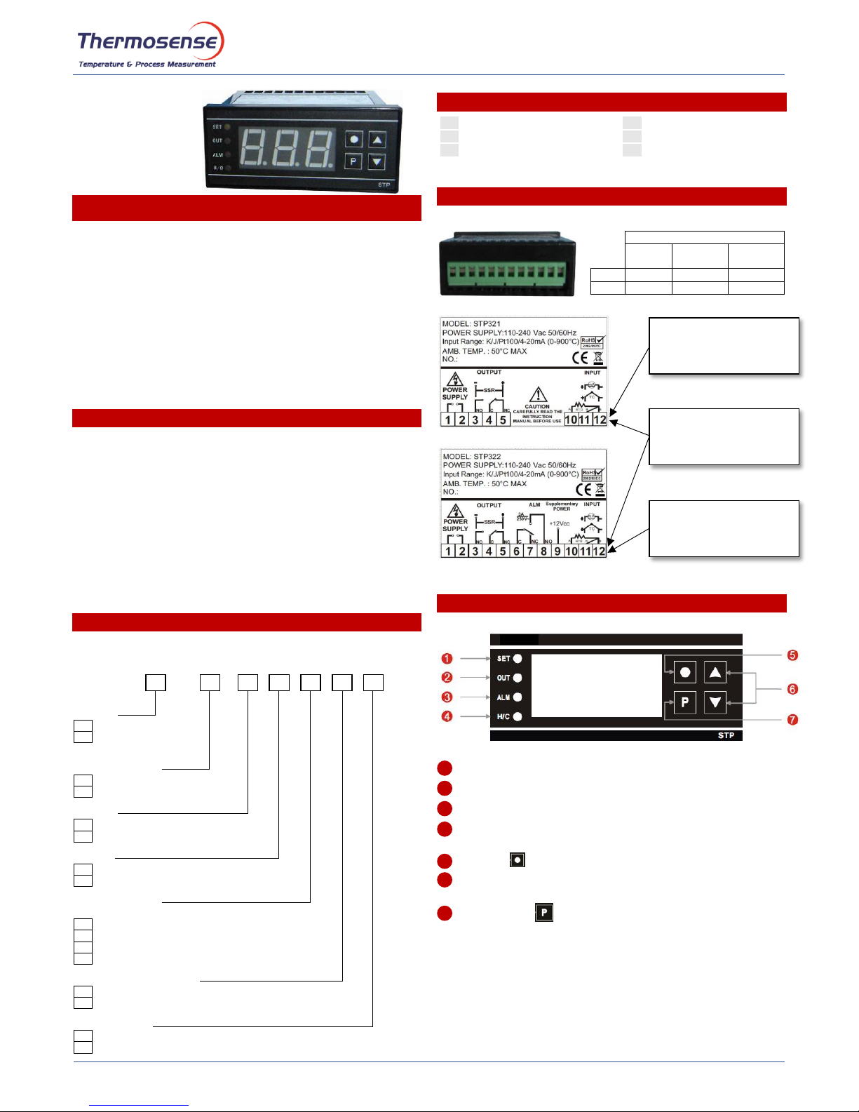
Order Code
Please check whether the delivered product is as specified by referring to the
following model code list. Please specify the model code when you place the order.
STP32
OUTPUT
1
One main control output
2
One main control output
and one alarm output
CONTROL ACTION
H
Heating
C
Cooling
OUTPUT
2
Relay output (15A/250V)
5
SSR logic output (12Vdc)
ALARM
N
No Alarm
Alarm active (choose the code - see Alarm code)
UNIVERSAL INPUT
Define factory setting of the input
1
K/J
2
PT100
5
4-20mA
8
PT1000
SUPPLEMENTARY POWER
N
No 12\/ output
V
With 12V output
POWER SUPPLY
7
100 to 240Vac
l
21 to 30Vac/dc
Alarm code
A
Deviation high alarm
B
Deviation low alarm
C
Deviation high and low alarm
D
Band alarm
H
Process high alarm
J
Process low alarm
Wire Connection
Front Panel
SET - LED will be “ON” when the user is changing the set point.
OUT - LED will be “ON” when the Output Relay / SSR drive is active.
ALM - LED will be “ON” when the alarm relay is active.
H/C - LED will be lit RED when the control action is Heating and
GREEN when the control action is Cooling.
Exit key
Press this key to exit from parameter setting mode.
"UP" and "DOWN" Keys - Press the keys to choose the parameters
and set the values. Press the "UP" key to show the software version.
Function key
Press this key 3 seconds to enter set point setting mode.
Press this key 6 seconds to enter parameters setting mode.
Sensor Input Range
PT100
(°C)
Type K
(°C)
Type J
(°C)
Min
-199
-30
-30
Max
+654
+999
+999
1 2 3
4 5 6
7
N.B. When using 4-20mA
Input, use a precision 250 Ω
resistor across terminals 11
and 12 to generate 1-5V input
N.B. For 2 wire RTD, white
lead 10, red lead 12 and link
pin 11 and 12
N.B. When using 4-20mA
Input, use a precision 250 Ω
resistor across terminals 11
and 12 to generate 1-5V input
STP321 / STP322 Programmable Thermostat Instruction Manual
Thermosense Limited
T: +44 (0)1628 531166
E: sales@thermosense.co.uk
W: www.thermosense.co.uk
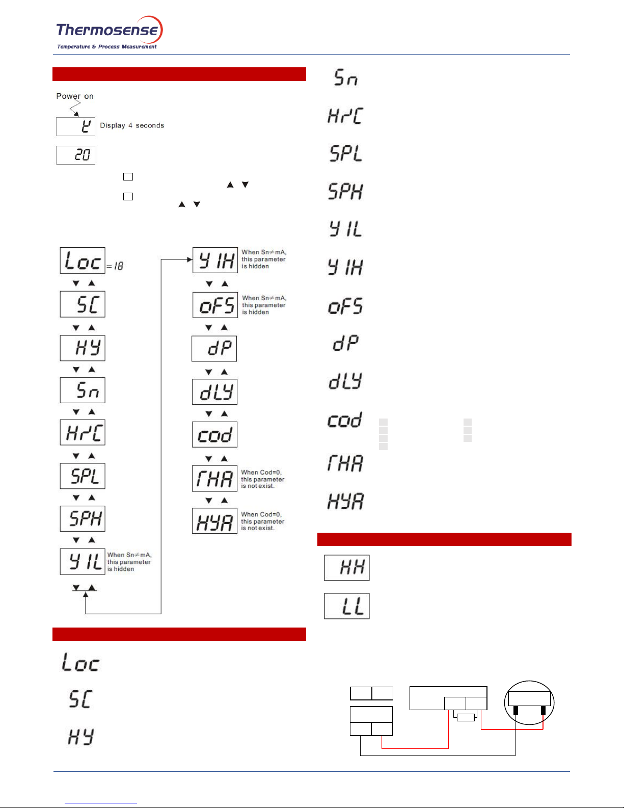
Operation
Press the function key for 3 seconds to enter the set point setting mode.
Then you can adjust the value with the up and down keys .
Press the function key for 6 seconds, then the window will display the following
parameters. Press the up and down keys to choose the parameters.
Note: Only when "Loc"=18 are all parameters programmable. When exiting the
program mode or after 10 sec of no key changes, “Loc” will default to “00”
Parameters Description
Lock parameter. The first parameter in the list.
The default value is 0.
To set following parameters, please set ”Loc”=18.
Compensation of the measuring value.
User can set this parameter when there is a difference between
measuring value and the real temperature.
Range: -19.9 to 20 degrees. Default: 0
Dead band of the control output.
For example: HY=5; SV=100; then the controller will start heating
when the SV=95; and stop heating when SV=105.
Range: 1-50 degrees. Default. 1
Input signal selection.
Press up or down key to choose the corresponding input sensor.
Range: K; J; Pt; mA
Default: K
Heating and cooling control action selection.
Press up or down key to choose the control action.
Range: heating H and cooling C
Default: H
Measurement low range
Range: -99 to 999°C
Default: 0
Measurement high range
Range: -99 to 999°C
Default: 900
Display value
When the input signal is mA, Y1L is the value for 4mA or 0mA.
When Sn ≠ mA, this parameter is hidden
When the input signal is mA, Y1H is the value for 20mA.
When Sn ≠ mA, this parameter is hidden
Selection of mA input range
YES = 4-20mA, NO = 0-20mA
When Sn ≠ mA, this parameter is hidden
Default: YES
Decimal point
dp=0, decimal point is inactive.
dp=1, decimal point is active.
Default: 0
Delaytime of main control output
Unit: Second
OUT indicating lamp should be light when the device is in delay time.
Default: 0
Alarm mode
0
No alarm
2
Deviation high and low alarm
1
Deviation high alarm
5
Deviation low alarm
3
Process high alarm
7
Process low alarm
6
Band alarm
Alarm value
Dead band of Alarm
Note: When alarm code is
C (Deviation high and low alarm) and D (Band alarm), this parameter
does not exist.
Error Occurrence
This code will be displayed when the temperature is higher than the
high limit of input sensor.
This code will be displayed when the input sensor crashed or the
temperature is lower than the low limit of input sensor.
- +
11(+)
12(-)
250 Ω
+
-
+
12-30Vdc
Loop power
-
4-20mA Transmitter
Source
External Power Supply
240Vac Input
STP321
4-20mA Input
Typical wiring layout for 4-20mA input signal with external
loop power supply and mA transmitter as source
P
P
 Loading...