

Thermoscreens VRF PHV1000 DXE HO, VRF PHV1500 DXE HO, VRF PHV2000 DXE LO, VRF PHV1500 DXE LO, VRF PHV2000 DXE HO Installation, Operation & Maintenance Instructions Manual
9901035-1 Page 1 of 30
PHV SURFACE MOUNTED HEAT PUMP AIR CURTAINS
INSTALLATION, OPERATION & MAINTENANCE INSTRUCTIONS
For use with CITY MULTI VRF units
PLEASE READ THESE INSTRUCTIONS CAREFULLY BEFORE ATTEMPTI NG INSTALLATION
Thermoscreens Ltd
St. Mary’s Road Nuneaton
Warwickshire England
CV11 5AU
Email: sales@thermoscreens.com
Tel: +44 (0) 24 7638 4646
Fax: +44 (0) 24 7638 8578
www.thermoscreens.com
English
9901035-1 Page 2 of 30
Thermoscreens / Mitsubishi Electric
Thermoscreens City Multi Heat Pump Air Curtains can be used with Mitsubishi Electric City
Multi Y/WY-Series (Heat Pump) or City Multi R2/WR2-Series (Heat Recovery) systems.
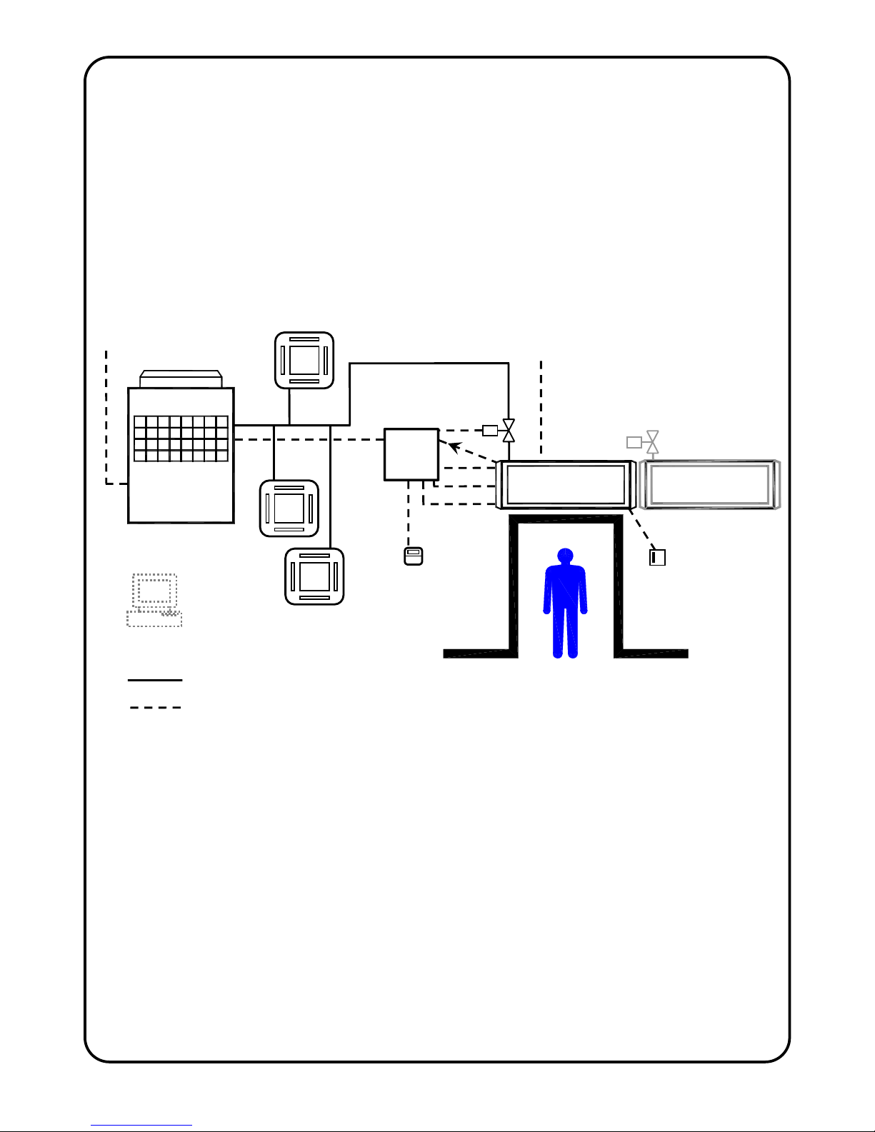
City Multi Y/WY-Series Heat Pump Air Curtain System
City Multi Y/WY-Series Heat Pump Air Curtain Schematic :-
City Multi Y-Series System: Indoor Units and Air Curtains(s) all operate on heating at the same time, or all operate on
cooling at the same time.
The City Multi Y Series Heat Pump Air Curtain system consists of :-
• One or more Thermoscreens VRF PHV Heat Pump (heating and cooling) Air Curtains *
• A Mitsubishi Electric PAC-AH…M-G AHU Controller or PAC-AH…M-H AHU Controller
(one for each air curtain) *
• A Mitsubishi Electric PAR-21MAA Remote Controller (one for each AHU Controller) +
• One or more Mitsubishi Electric City Multi Y/WY-Series Compressor Unit +
• Mitsubishi Electric Indoor Unit(s)
+
[NB. Can be used on a full air curtain basis if required
up to 100% diversity]
• Mitsubishi Electric BMS System or Centralised Controller, if required
+
* - supplied by Thermoscreens Ltd.;
+
- supplied by others
Heat Pump
Air Curtain
Mitsubishi Electric
Com
p
resso
r
Unit
LEV(s)
PAC-AH AHU
Controller
BMS Control
Fan
Sensors
Mitsubishi Electric
Indoor Units
Permanent electrical supply
(from local switched spur)
PAR-21MAA
remote
controlle
r
Defrost signal
Refrigeration pipework
Electrical/Controls cables
1 per air
curtain
Powe
r
Permanent mains electrical supply
(from local switched spur) for:
x Fans
x Defrost electric heaters (if used)
x PAC-AH…AHU Controller
Remote
3-Speed
Fan Switch
Cond. alarm
9901035-1 Page 3 of 30
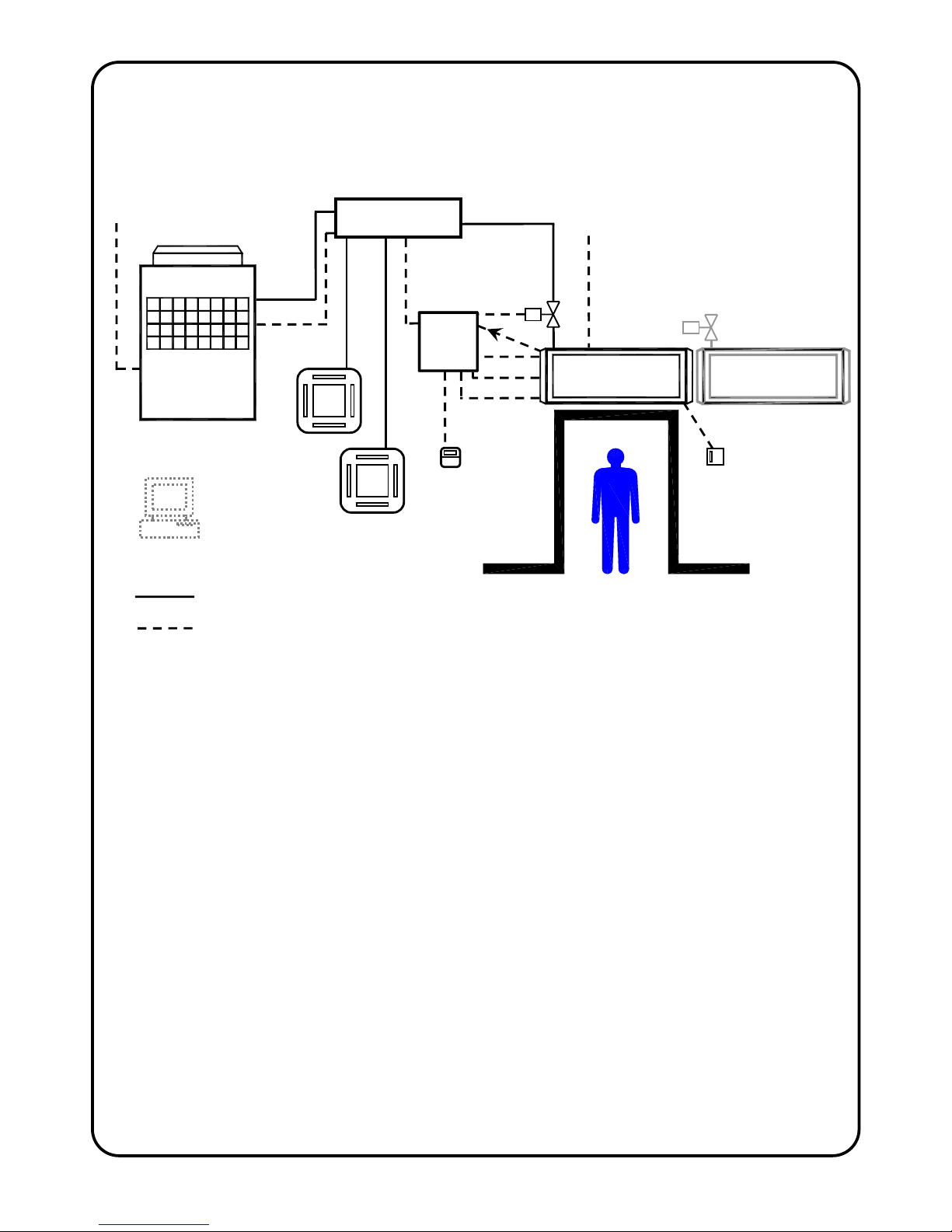
City Multi R2/WR2-Series Heat Pump Air Curtain System
City Multi R2/WR2-Series Heat Recovery Heat Pump Air Curtain Schematic :-
City Multi R2/WR2-Series System: Indoor Units and Air Curtains(s) can operate on heating or cooling simultaneously, e.g.
some indoor units are cooling whilst other indoor units and air curtain are heating at the
same time.
The City Multi R2/WR2-Series heat recovery system with Heat Pump Air Curtain(s) consists
of :-
• One or more Thermoscreens VRF PHV Heat Pump (heating and cooling) Air Curtains *
• A Mitsubishi Electric PAC-AH…M-G AHU Controller or PAC-AH…M-H AHU Controller
(one for each air curtain) *
• A Mitsubishi Electric PAR-21MAA Remote Controller (one for each AHU Controller)
+
• One or more Mitsubishi Electric City Multi R2/WR2-Series Compressor Unit
+
• Mitsubishi Electric BC Controller
+
• Mitsubishi Electric Indoor Unit(s)
+
[NB. Can be used on a full air curtain basis if required
up to 100% diversity]
• Mitsubishi Electric BMS System or Centralised Controller, if required +
* - supplied by Thermoscreens Ltd.; + - supplied by others
Heat Pump
Air Curtain
Mitsubishi Electric
Compressor Unit
Permanent mains electrical supply
(from local switched spur) for:
x Fans
x Defrost electric heaters (if used)
x PAC-AH…AHU Controller
PAC-AH AHU
Controller
BMS Control
Fan
Sensors
Mitsubishi Electric
Indoor Units
Permanent electrical supply
(from local switched spur)
PAR-21MAA
remote
controller
Defrost signal
BC Controller
Refrigeration pipework
Electrical/Controls cables
1 per air
curtain
LEV(s)
Remote
3-Speed
Fan Switch
Power
Cond. alarm
9901035-1 Page 4 of 30
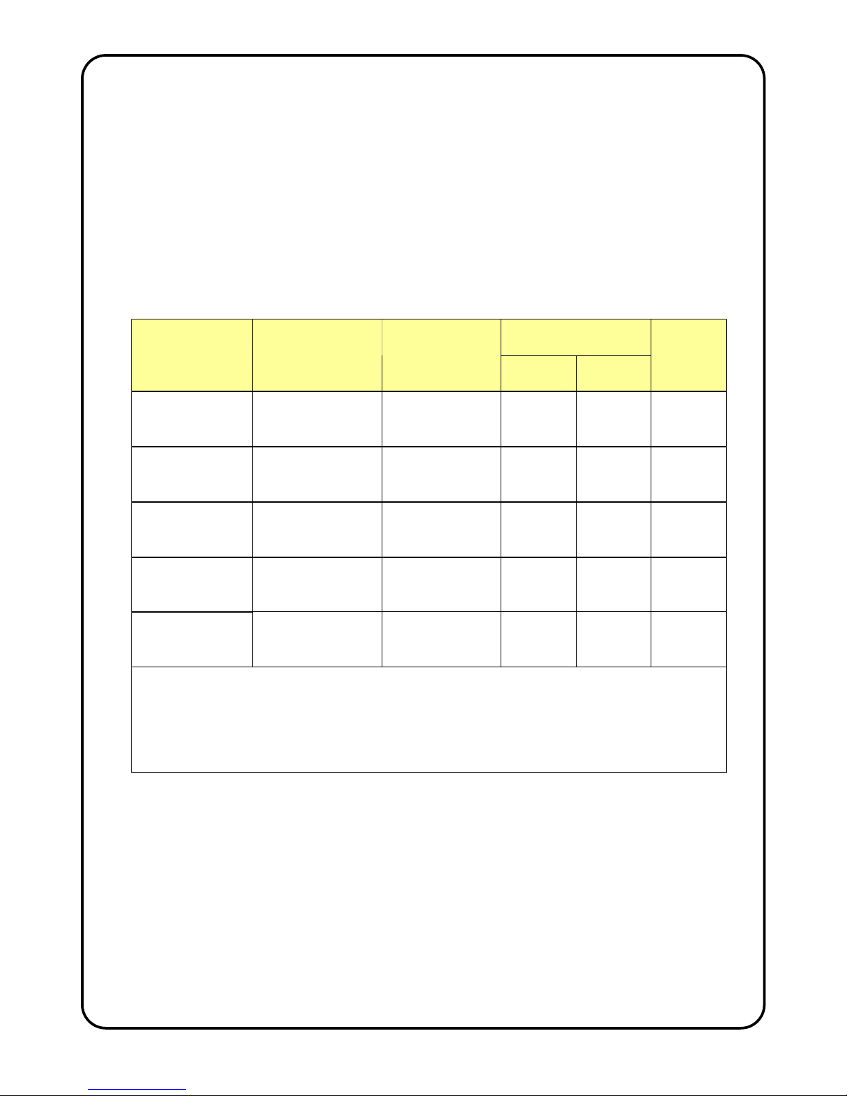
DESIGN INFORMATION
Each Thermoscreens Heat Pump Air Curtain needs to operate with a Mitsubishi Electric
PAC-AH…AHU Controller. There are two versions that can be used; PAC-AH…M-G and
PAC-AH…M-H the supply of which is dependent on the EU state where the installation is
being carried out.
The rated size of the PAC-AH…AHU Controller needs to be matched to the size of the
heat pump air curtain. Each size of AHU Controller comes with different size LEV(s) and
number of LEVs so they need to be matched to the air curtain. The table shows the AHU
Controller to be selected and maximum outputs and air volume flow rates of the heat
pump air curtain.
Maximum Heat
Pump Output (kW)
Air Curtain
PAC-AH…AHU
Controller
LEV(s)
No.Off
Index Size
Heating Cooling
Air
Volume
Flow
(m3/h)
VRF PHV1000
DXE HO
PAC-AH125M-G
or
PAC-AH125M-H
Type P632411X01
1 off
P100
9.0 8.1 1400
VRF PHV1500
DXE LO
PAC-AH125M-G
or
PAC-AH125M-H
Type P632411X01
1 off
P125
10.6 9.0 2500
VRF PHV1500
DXE HO
PAC-AH140M-G
or
PAC-AH140M-H
Type P632414X01
1 off
P140
15.1 13.6 2600
VRF PHV2000
DXE LO
PAC-AH140M-G
or
PAC-AH140M-H
Type P632414X01
1 off
P140
16.4 14.8 3300
VRF PHV2000
DXE HO
PAC-AH250M-G
or
PAC-AH250M-H
Type P632411X01
2 off
P200
21.4 19.3 3130
Maximum heat pump output refers to the heating or cooling output from the air curtain air stream.
Figures are derived from laboratory testing with reference to test standard EN14511. They are with
the air curtain operating at high fan speed, outdoor air temperature 7/6°C db/wb indoor air
temperature 20°C db for heating; outdoor air temperature 35/27°C db/wb indoor air temperature 27°C
db for cooling. Contact Mitsubishi Electric for performance at other outdoor and indoor conditions.
The air curtain normally operates under automatic temperature control set on the PAR-21MAA remote
controller and can also run at part load.
The following City Multi compressor units can be connected:
For Y/WY-Series systems:
PUHY-(E)P200 …. 1250Y(S)HM-A
PQHY-P200 …. 600Y(S)HM-A
PUMY-P100 …. 140V(Y)HMB
PUHY-HP200 …. 500Y(S)HM-A
For R2/WR2-Series systems:
PURY-(E)P200 …. 800Y(S)HM-A
PQRY-P200 …. 600Y(S)HM-A

9901035-1 Page 5 of 30
The Thermoscreens Air Curtain requires a permanent mains electrical supply from a local
switched isolator. Electrical power to the PAC-AH…AHU controller is then fed from the air
curtain. Electrical power to the Mitsubishi Electric compressor unit(s) and BC Controller is
fed separately in the normal way (see separate Mitsubishi Electric instructions). If the
defrost cycle electric heaters inside the air curtain are to be used during the heating mode
defrost cycle the electrical supply to the air curtain needs to be 3-phase (3L+N+E). If the
defrost cycle electric heaters are not required they can be permanently disconnected at
installation and a single phase electrical supply (1L+N+E) fed to the air curtain instead,
see 'Installation - Electrical Supply'.
Warning: Air curtain fans continue to operate during heating mode system defrost to
maintain an air stream across the doorway. With the defrost cycle electric heaters
operating the discharge air temperature from the air curtain is kept to a few degrees below
that of the indoor ambient air temperature during the duration of system defrost. If the
electric heaters are disconnected, discharge air temperatures could be very cold,
approximately 6ºC during the defrost and defrost times will also be extended, particularly
with the R2-Series System. Defrost does not occur with WY and WR2 systems so the
defrost cycle electric heaters should be disconnected on these systems.
There are various control cables that are wired on site to the PAC-AH…AHU Controller
and the Thermoscreens Air Curtain that provide control for the operation of the unit. These
are:-
• Start/Stop of air curtain fans
• Operation of LEV(s) for control of heating or cooling output
• Thermistor sensors
• PAR-21MAA Remote Controller for end user manual control, if used
• On/Off of electric heaters inside the air curtain during system defrost (if used)
• Condensate alarm derived from condensate pump alarm sensor (if used)
• M-Net communications link to the Mitsubishi Electric Compressor Unit.
(see also wiring diagrams)
The Thermoscreens Air Curtain is supplied with an integral condensate drain tray to
enable the air curtain to be used in cooling mode during warm weather, if so desired. If it is
intended to use the air curtain in cooling mode a suitable condensate pump (not supplied
by Thermoscreens) must be supplied by the installer. The condensate pump must be of
sufficient capacity, self priming and capable of providing the appropriate suction head so
the pump will lift condensate out from the top of the air curtain but can be hidden in a
remote location if necessary. Suitable condensate pumps are Peristaltic or Rotary
Diaphragm type. We recommend the Blue Diamond rotary diaphragm type with cooling
signal sensor (drainStik) manufactured by Charles Austen Pumps Ltd.
(www.miniblue.co.uk).
It is recommended that the condensate pump has the facility so it only operates when the
air curtain is in cooling mode by detection of water in the drain tray or by detecting a
cooling differential in the airflow. It should also have a pump overrun to empty the drain
tray as much as possible when the air curtain is switched off. It should have an alarm
system with appropriate sensor that will give a volt-free signal (open circuit = alarm). This
will stop the air curtain cooling if the condensate drain tray is in danger of flooding, air
curtain fans will continue to operate. Other City Multi indoor units are unaffected if the air
curtain condensate alarm occurs. There is a plastic fixing bracket with 8mm diameter hole

9901035-1 Page 6 of 30
attached to the drain tray inside the air curtain so a condensate sensor can be fixed in the
tray by the installer. The hole can be enlarged, if necessary, to suit the type of sensor used
so it is located in the tray at the appropriate position, see the manufacturer’s instructions
that come with the condensate pump for further information. The 230v AC, single phase
electrical supply to operate the condensate pump will come from the air curtain.
Warning: The air curtain condensate collection system is designed to remove condensate
with the air curtain operating in cooling mode during normal summer weather conditions in
countries with a temperate climate. In case of extreme weather conditions or condensate
pump failure, which can occur, it is vital that the design of the floor beneath the air curtain
and its surface is such that it will not become slippery or damaged if it became wet. This is
similar to the conditions that might be experienced with heavy rainfall or wet pedestrian
foot traffic at an open doorway, so careful consideration must be paid to the design of the
floor and its finish.
If it is intended that the air curtain should not be operated in cooling mode and a
condensate pump is not fitted, the BMS System, Centralised Controller or PAR-21MAA
manual Remote Controller must be configured at commissioning so that COOL or AUTO
mode can never be selected (see Section – Commissioning). It is still recommended,
however, that the floor design and surface be as described above in case cooling mode is
used in the future and to cope with heavy rainfall or wet pedestrian foot traffic.
Note: It could still be possible for an end user to unlock a PAR-21MAA Remote Controller
if they found out how to and switch it into cooling, not realising that condensate would then
flood out of the drain tray. It may therefore be considered prudent to install a condensate
pump and drain system even if it is intended that the unit should only be used in HEAT or
FAN mode.
If a Building Management System (BMS) or Centralised Controller is to be used for control
of the air curtain please contact Mitsubishi Electric for more details.
The air curtain is designed only for use with a Mitsubishi Electric City Multi VRF system for
use on R410A. The complete Thermoscreens/Mitsubishi Electric heat pump system,
including fridge pipework, wiring, controls, etc. must be installed only by an approved
Mitsubishi Electric refrigeration contractor.
The air curtain is not intended for use by persons (including children) with reduced
physical, sensory or mental capabilities, or lack of experience and knowledge, unless they
have been given supervision or instruction concerning the use of the appliance by a
person responsible for their safety.
High Output (HO) and Low Output (LO) in this document refers to the heat pump heating
or cooling capacity of the Air Curtain, not to any electrical rating. HO air curtains have a 3row coil, LO air curtains have a 2-row coil.
These instructions must be read in conjunction with the Mitsubishi Electric instructions that
come with other components of the heat pump system, e.g. Compressor Unit, BC
Controller, PAR-21MAA Remote Controller, BMS System, Centralised Controller, etc.
They should be kept by the building facilities manager for future reference.
9901035-1 Page 7 of 30
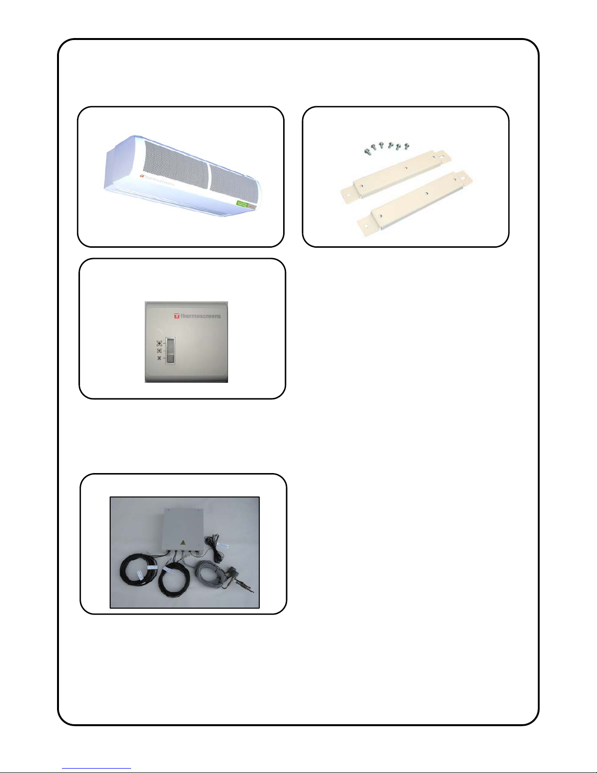
UNPACKING THE HEAT PUMP AIR CURTAIN
The following items are supplied and packaged within the Thermoscreens air curtain box.
The Mitsubishi Electric PAC-AH…M-G AHU Controller or PAC-AH…M-H AHU Controller
comes in its original Mitsubishi Electric box. It is delivered with the larger Thermoscreens air
curtain box. It is factory pre-wired as much as possible to reduce installation time on site.
Check with the cross-reference labels on the Thermoscreens air curtain box and the
Mitsubishi Electric AHU Controller box that the correct AHU Controller is matched with the
correct air curtain.
Other components for the heat pump system are as described above on the System
Schematics on pages 2 and 3.
Wall Brackets and Fixing Bolts
City Multi Heat Pump Air Curtain
Please note, end caps are supplied loose
to be fitted during installation
Remote 3-Speed Fan Switch
PAC-AH..M-G or M-H..AHU Controller
9901035-1 Page 8 of 30
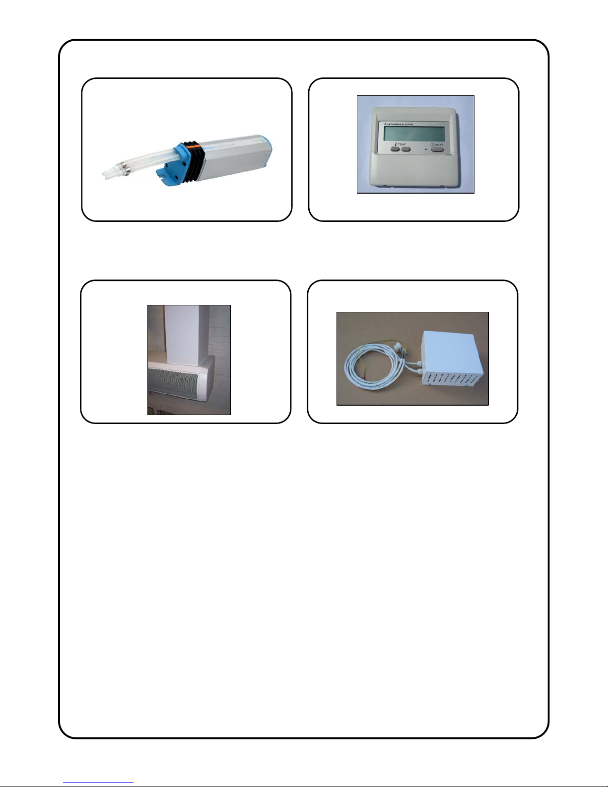
The Installer will also need to supply and install the following:-
The following optional equipment is also available for the air curtain:-
For your records:
Date of Purchase……………………………..
Place of Purchase…………………………….
Serial Number…………………………………
For warranty purposes proof of purchase is necessary so please keep a copy of your invoice.
Sheet metal covers to hide services Fan Speed Controller for low speeds
Condensate Pump – self priming with
cooling mode detection, alarm
system and pump overrun
PAR-21 MAA Remote Controller
If Air Curtain is to be manually controlled,
also needed for commissioning
If Air Curtain is to be operated in COOL or
AUTO mode – see text for more information
9901035-1 Page 9 of 30
INSTALLATION OF THE HEAT PUMP AIR CURTAIN
The air curtain is designed to be surface mounted inside of the building and located
over a doorway. It must not be installed outside of the building, or built into a
cabinet or recessed in any way.
Location
The air curtain must be mounted so the discharge grille is
between 1.8m minimum and 3.75m maximum above floor
level and situated as close to the doorway as possible.
Beware of doorway top edges, structural beams, door
opening devices, etc. which may interfere with the air
stream and affect the location of the unit. The air curtain
must be installed level or condensate may leak out,
particularly if it tilts down at the left hand side (looking out
of the doorway from inside). It is better to tilt down slightly
at the right hand side as the drain tray spout is this side.
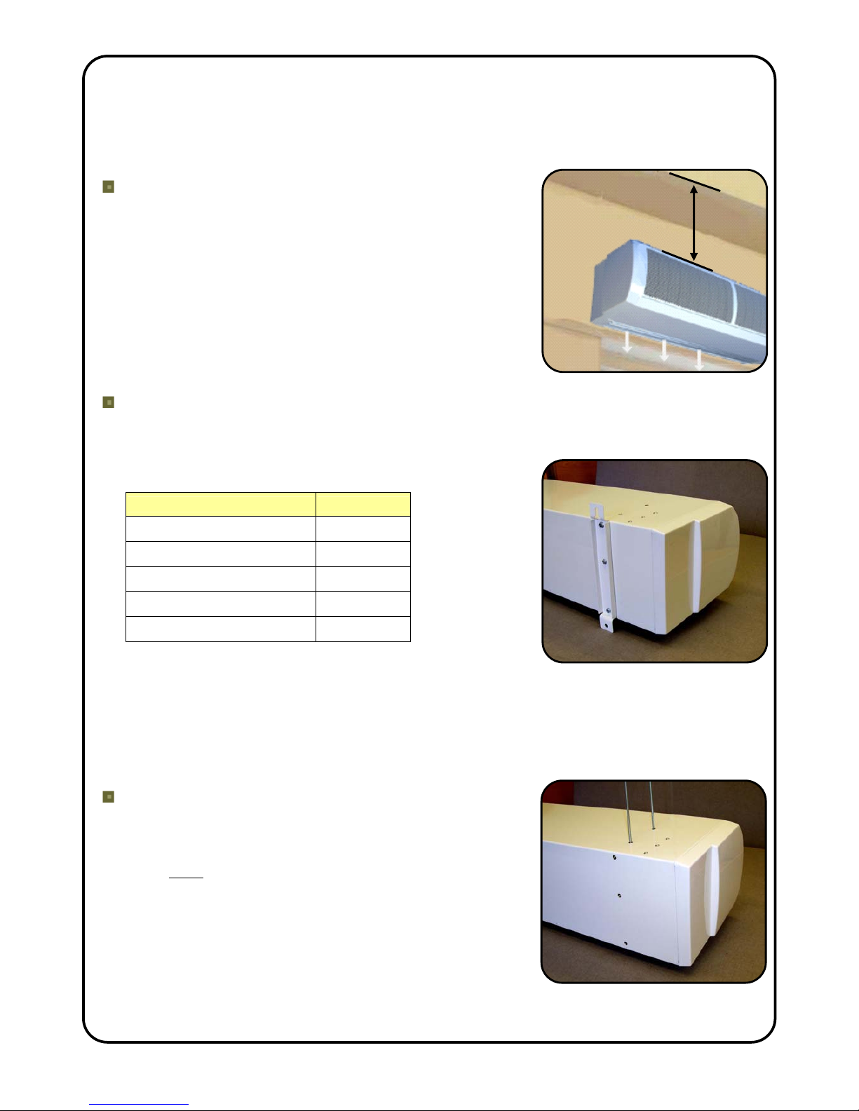
Wall Fixing
Bolt all of the wall brackets supplied to the rear face of the unit as shown in the adjacent
picture using the M6 bolts supplied. Suitable wall fixing bolts (not supplied) need to be
used to fix the brackets to the wall, taking into account the
type of wall and the weight of the unit*, see table:
Air Curtain Weight (kg)
VRF PHV1000 DXE HO 39
VRF PHV1500 DXE LO 59
VRF PHV1500 DXE HO 60
VRF PHV2000 DXE LO 78
VRF PHV2000 DXE HO 80
Step 1. Refer to Figure 1 for mounting details and drill the
fixing points in the wall.
Step 2. Screw in the top wall bolts leaving a small gap between the head and the wall.
Lower the unit onto the bolts via key-hole slots in the top of the wall brackets and then
screw in the bottom wall bolts.
Step 3. Ensure all fixing bolts are tightened and the air curtain is safely secured to the
wall.
Ceiling Suspension
M10 threaded inserts are provided in the top face of the
unit (see Figure 1 for positions) so it can be suspended on
M10 threaded hanging rods (not provided). All suspension
points must be used. Ensure each of the hanging rods is
secured onto a suitable structure that can support the
weight of the unit (see table above)*. Screw the hanging
rods into the inserts by a minimum of 20mm and fit
locking nuts (not supplied) to prevent the rod rotating and
coming away from the casing. Do not screw the hanging
rod too far in or it will interfere with internal components.
* It is the sole responsibility of the installer to ensure that the building fixing locations and
suspension system used are suitable for the air curtain being installed.
250mm min
 Loading...