

Thermoscreens T1500A, T1500W, T1500E, T2000A, T2000E User Manual
...
AIR CURTAIN
T SURFACE MOUNTED RANGE
INSTALLATION, OPERATION AND
MAINTENANCE INSTRUCTIONS
T9901009-1-1 UK (v9) Page | 1
English

1 CONTENTS
CONTENTS ...................................................................................................................................... 2
1
2 ELECTRICAL SAFETY ..................................................................................................................... 3
3 SPECIFICATIONS ............................................................................................................................ 3
4. INTRODUCTION .............................................................................................................................. 4
5. DELIVERY CONTENTS ................................................................................................................... 5
6. TOOLS REQUIRED .......................................................................................................................... 5
7. INSTALLATION ................................................................................................................................ 6
8. ELECTRICAL CONNECTION .......................................................................................................... 8
9. REMOTE CONTROL INSTALLATION ............................................................................................. 9
10. REMOTE CONTROL SETTINGS ..................................................................................................... 9
11. EXTERNAL CONTROLS ................................................................................................................ 10
12. MULTIPLE AIR CURTAIN SYSTEMS ............................................................................................ 11
13. SYSTEM CONFIGURATION .......................................................................................................... 12
14. FAN SPEED SELECTION .............................................................................................................. 13
Page
15. REMOTE CONTROL OPERATION ................................................................................................ 14
16. COMMISSIONING THE SYSTEM .................................................................................................. 16
17. SIGN OFF ....................................................................................................................................... 16
18. FAULT CONDITIONS ..................................................................................................................... 17
19. SERVICE & MAINTENANCE ......................................................................................................... 18
20. WARRANTY ................................................................................................................................... 19
APPENDIX 1 — Dimensions of T Surface Mounted Air Curtain ............................................................... 20
APPENDIX 2A — WIRING DIAGRAM T1000E and T1500E .................................................................. 21
APPENDIX 2B — WIRING DIAGRAM T2000E ....................................................................................... 22
APPENDIX 2C — WIRING DIAGRAM T1000W, T1500W and T2000W ................................................ 23
APPENDIX 2D — WIRING DIAGRAM T1000A, T1500A and T2000A ................................................... 24
21. DECLARATION OF CONFORMITY ............................................................................................... 25
T9901009-1-1 UK (v9) Page | 2
2 ELECTRICAL SAFETY
Electrical Supply and Wiring to the Air Curtain
All electrical wiring and connections MUST be carried out by a competent qualified electrici an in
accordance with the latest edition of national and local wiring regulations and/or local statutory
regulations.
A 1 phase or 3 phase local isolator having a contact separation of at least 3mm on all poles
must be fitted in the electrical supply to the air curtain and located in an accessible position
adjacent to the unit.
The appliance must be connected by cables having an appropriate heat resistant temperature
rating.
All supply cables, circuit breakers and other electrical installation equipment must be correctly
sized for the air curtain model being installed; see section 3: Specifications.
Models operating on a 3 phase electrical supply - see section 3: Specifications - require a
neutral connection (3N~).
A 25mm size cable gland or conduit connector of IP21 rating or above should be used for the
Electrical Supply into the air curtain.
See Wiring Diagrams for connecting electrical supply and control cables to the air curtain. The
air curtain must be earthed.
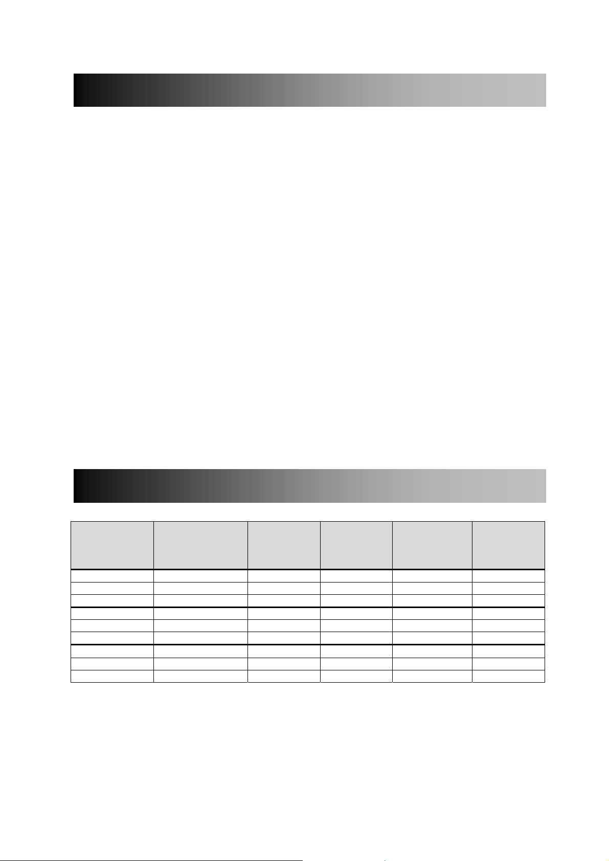
3 SPECIFICATIONS
Rated
Air Curtain
Model No
T1000A 230/1/50 0.25 1.1 – 27
T1500A 230/1/50 0.35 1.5 – 40
T2000A 230/1/50 0.45 2.0 – 50
T1000W 230/1/50 0.25 1.1 4.5 / 9.0 29
T1500W 230/1/50 0.35 1.5 6.0 / 12.0 42
T2000W 230/1/50 0.45 2.0 9.0 / 18.0 53
T1000E 400/3/50 9.25 14.1 6.0 / 9.0 28
T1500E 400/3/50 12.35 18.9 6.0 / 12.0 41
T2000E 400/3/50 18.45 28.1 12.0 / 18.0 52
Electrical Supply
(V/ph/Hz)
Electrical
Power Input
(kW)
Rated
Current per
phase (A)
Heat Output
[Low/High]
(kW)
Table 1
Weight
(kg)
T9901009-1-1 UK (v9) Page | 3

4. INTRODUCTION
Established in the 1960s, Thermoscreens is a leading air curtain manufacturer that exports to over 60
countries worldwide.
As with all our products, the T range of air curtains is designed with energy efficiency in mind.
T models suffixed E, W or A are designed to be surface mounted inside a building and located
horizontally over a doorway.
They must not be installed on the outside of a building or built into a cabinet or recessed in any way.
Please complete the following details for your reference:
Date of Purchase
Place of Purchase
Serial Number
Proof of purchase is required to make a claim under warranty.
Thermoscreens Ltd
St. Mary’s Road
Nuneaton
Warwickshire
England
CV11 5AU
Email: sales@thermoscreens.com — http://www.thermoscreens.com
Tel: +44 (0) 24 7638 4646 — Fax: +44 (0) 24 7638 8578
T9901009-1-1 UK (v9) Page | 4
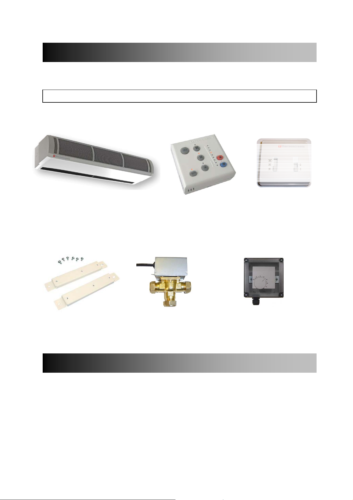
5. DELIVERY CONTENTS
y
The following items are supplied in the box at delivery.
NOTE: If any parts are missing or damaged contact your place of purchase.
T Surface Mounted Air Curtain Ecopower Remote Control
Note: End caps are supplied loose to
be fitted during installation
Wall Brackets and
M6 Fixing Bolts
(for water heated units)
3-port control valve
Fitted in pipework to
air curtain b
(for Electric and Water Heated units)
Supplied with 6m
RJ Control Cable
Outdoor Air Thermostat
(Optional – supplied by Installer)
Used for simple weather
installer
(disables heating on a warmer day)
Remote Control Switch
(for Ambient units)
compensation control
6. TOOLS REQUIRED
The following tools are required for installation:
Flat blade screwdrivers
Pozi head screwdrivers
10mm spanner
Adjustable spanner
T9901009-1-1 UK (v9) Page | 5
Electric drill
Ladders
Appropriate lifting equipment
7. INSTALLATION
The air curtain is designed to be located horizontally over a doorway. It must not be installed outside of
the building.
7.1 Location
Mount the air curtain above and as close to the doorway as
possible, with:
the discharge grille not more than 3m above floor level
at least 100mm clearance (air gap) above electric/water
heated air curtains, see Fig 1
Beware of doorway top edges, structural beams, door
opening/closure devices, etc., which may interfere with the air
stream and affect the location of the unit.
NOTE: For the air curtain to work well the width of the open doorway should be less than the length
‘A’ of the air curtain, see Appendix 1.
100mm
3000mm
Fig 1
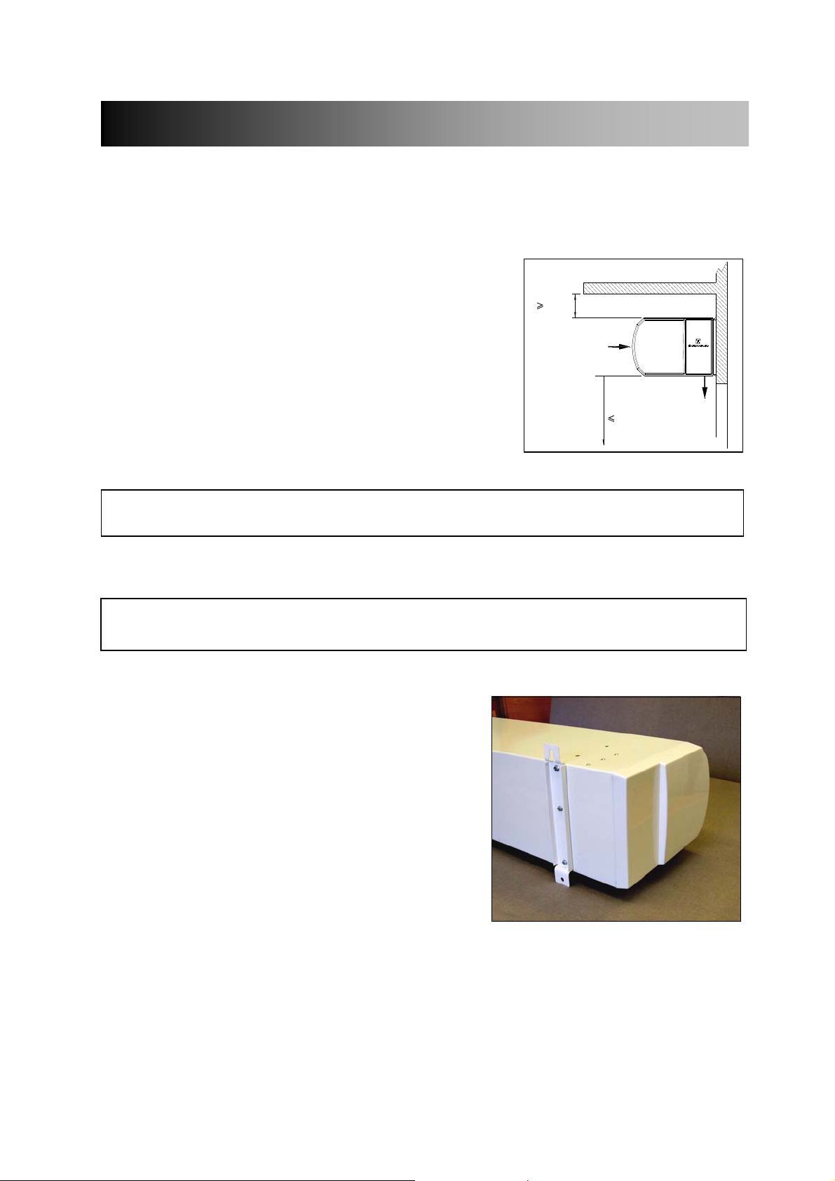
7.2 Wall Fixing
NOTE: Use suitable wall fixing bolts (not supplied) to fix the unit to the wall, taking into account the
Step 1 Bolt all wall brackets to the rear face of the unit
Step 2 Drill fixing points in the wall, referring to
Step 3 Screw in the top wall bolts leaving a small gap
Step 4 Lower the unit onto the bolts via the key-hole
Step 5 Tighten all fixing bolts until the air curtain is
type of wall and the weight of the unit (see Section 3: Specifications).
as shown in Fig 2, using the M6 fixing bolts
supplied.
Appendix 1 for correct positioning.
between the screw head and the wall.
slots in the top of the wall brackets and screw in
the bottom wall bolts.
Fig 2
safely secured to the wall.
T9901009-1-1 UK (v9) Page | 6
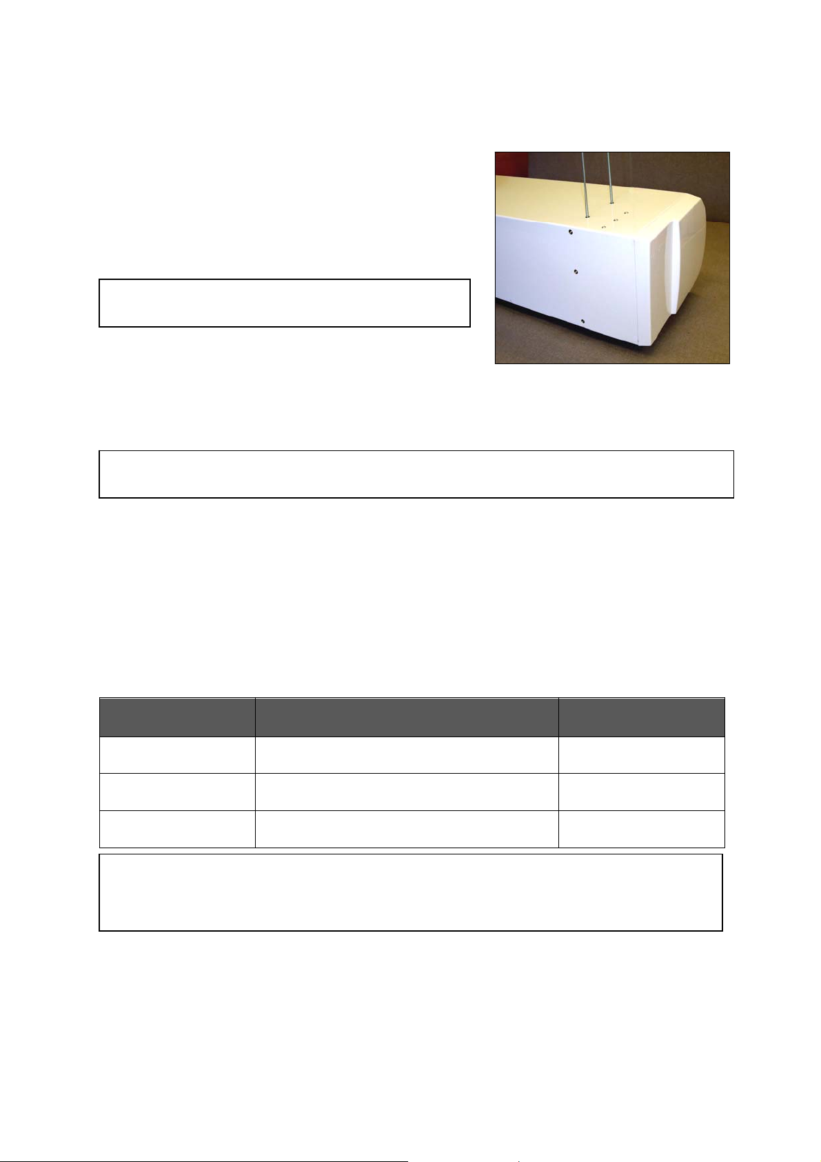
7.3 Ceiling Suspension
M10 threaded rods (not supplied) are used to suspend the
unit from the ceiling.
Suspend the unit from the ceiling as follows:
Step 1 Screw the threaded rods into all of the holes in the
top face of the unit as shown in Fig 3.
NOTE: Do not screw hanging rods too far in as they
Step 2 Fit M10 locking nuts (not provided) to prevent the
Step 3 Secure each suspension rod to a suitable structure that can support the weight of the unit (see
WARNING: It is the sole responsibility of the installer to ensure that the fixing locations and
could interfere with internal components.
rod rotating and coming away from the casing.
section 3: Specifications for weights).
suspension system used are suitable for the air curtain being installed.
Fig 3
7.4 LPHW Models
For LPHW models ensure that water isolation valves are fitted in the flow and return pipework
adjacent to the air curtain and connected correctly as shown in the diagram in Appendix 1.
For the design of the water pipework system and pump, water flow rates and pressure drops for
maximum heat output of the air curtain are given in Table 2 below.
Air Curtain Water Flow Rate
(l/min at 82/71°C)
T1000W, 2-row
(9kW)
T1500W, 2-row
(12kW)
T2000W, 2-row
(18kW)
NOTE: Water Pressure Drop is across the flow and return pipework to the air curtain and includes for the
coil fitted inside the unit and the valve fitted in the heating pipework to the unit.
Water flow rates and pressure drops at different water temperatures can be calculated using the
Thermoscreens coil calculation programme. Visit the Thermoscreens website for details.
11.7 9.0
15.6 16.6
23.4 12.5
Water Pressure Drop
(kPa)
Table 2
T9901009-1-1 UK (v9) Page | 7
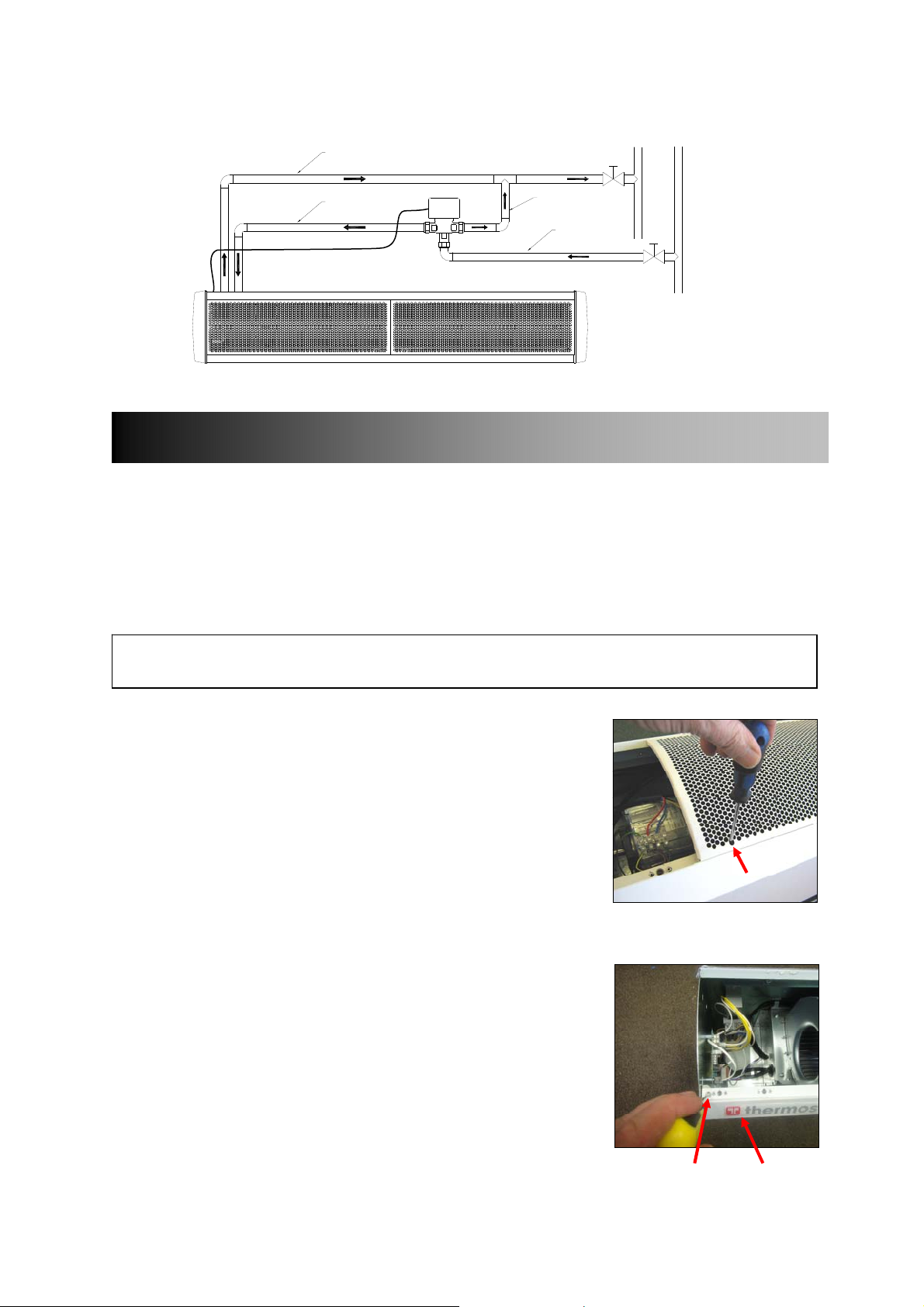
The installer must connect the 3-port valve in the heating pipework as shown in Figure 4 below:
22mm pipe
R
22mm pipe
wire valve to pcb inside air curtain
22mm pipe
A
B
A/B
22mm pipe
F
E
L
T
O
U
W
R
N
Fig 4
8. ACCESS TO ELECTRICAL CONNECTIONS
8.1 How to access terminals
To gain access to the air curtain for connection and commissioning, remove air inlet grilles and bottom
access panel as explained below.
First remove the plastic end caps at each end of the unit, if fitted, by pulling off to the side.
NOTE: All air curtain panels are protected in a plastic film. When access panels are removed this
8.1.1 Remove air inlet grilles
Using a Pozi No 1 screwdriver, remove each grill with its filter.
To remove, insert screwdriver into the elongated hole at the bottom
corner of the grille (see Fig 5) and turn the screw one quarter of a turn
anticlockwise.
8.1.2 Remove bottom access panel
Unfasten the securing screw at each end (see 1, Fig 6) and, if
applicable, two screws in the centre (T1500 and T2000 units only).
To remove, slide the access panel (see 2, Fig 6) out forwards.
film can be removed.
Fig 5
Fig 6
1
2
T9901009-1-1 UK (v9) Page | 8
 Loading...