

Thermoscreens HX Series, HX2000AR, HX1000WR, HX1500WR, HX1500AR Installation, Operation And Maintenance Instructions
...
HX Series.
Recessed Range
9901098-2-1
INSTALLATION, OPERATION AND
MAINTENANCE INSTRUCTIONS
English
Page | 1

1 CONTENTS
CONTENTS ...................................................................................................................................... 2
1
2 ELECTRICAL SAFETY ..................................................................................................................... 3
3 SPECIFICATIONS ............................................................................................................................ 3
4. INTRODUCTION .............................................................................................................................. 4
5. DELIVERY CONTENTS ................................................................................................................... 5
6. TOOLS REQUIRED .......................................................................................................................... 5
7. INSTALLATION ................................................................................................................................ 6
8. REMOTE CONTROL INSTALLATION ............................................................................................. 9
9. REMOTE CONTROL SETTINGS ..................................................................................................... 9
10. EXTERNAL CONTROLS ................................................................................................................ 10
11. SYSTEM CONFIGURATION .......................................................................................................... 11
12. MULTIPLE AIR CURTAINS ............................................................................................................ 12
13. FAN SPEED SELECTION .............................................................................................................. 13
14. REMOTE CONTROL OPERATION ................................................................................................ 14
15. COMMISSIONING THE SYSTEM .................................................................................................. 15
16. SIGN OFF ....................................................................................................................................... 15
17. FAULT CONDITIONS ..................................................................................................................... 16
18. SERVICE & MAINTENANCE ......................................................................................................... 17
19. WARRANTY ................................................................................................................................... 18
APPENDIX 1 — DIMENSIONS OF HX RECESSED AIR CURTAIN ....................................................... 19
APPENDIX 2A — WIRING DIAGRAM -HX1000ER ................................................................................. 20
APPENDIX 2B — WIRING DIAGRAM HX1500ER .................................................................................. 21
APPENDIX 2C — WIRING DIAGRAM HX2000ER .................................................................................. 22
APPENDIX 2D — WIRING DIAGRAM HX1000WR, HX1500WR and HX2000WR ................................. 23
APPENDIX 2E — WIRING DIAGRAM HX1000AR, HX1500AR and HX2000AR .................................... 24
20. DECLARATION OF CONFORMITY ............................................................................................... 25
9901098-2-1 Page | 2

2 ELECTRICAL SAFETY
Electrical Supply and Wiring to the Air Curtain
All electrical wiring and connections MUST be carried out by a competent qualified electrici an in
accordance with the latest edition of the IEE wiring regulations and/or local statutory regulations.
A single phase or 3 phase local isolator having a contact separation of at least 3mm on all
poles must be fitted in the electrical supply to the air curtain and located in an accessible
position adjacent to the unit.
The appliance must be connected by cables having an appropriate heat resistant
temperature rating.
All supply cables, circuit breakers and other electrical installation equipment must be
correctly sized for the air curtain model being installed; see section 3: Specifications.
Models operating on 3 phase electrical supply - see section 3: Specifications - require a
neutral connection (3N~).
A 25mm size cable gland or conduit connector should be use d for the Electrical Supply
into the air curtain.
The air curtain must be earthed.
3 SPECIFICATIONS
Air Curtain
HX1000AR 230/1/50 0.2 0.8 – 1.10 45
HX1500AR 230/1/50 0.3 1.2 – 1.63 66
HX2000AR 230/1/50 0.35 1.4 – 2.15 80
HX1000WR 230/1/50 0.2 0.8 6/12 1.10 52
HX1500WR 230/1/50 0.3 1.2 9/18 1.63 75
HX2000WR 230/1/50 0.35 1.4 12/24 2.15 93
HX1000ER 400/3/50 12.2 18.2 6/12 1.10 46
HX1500ER 400/3/50 18.3 27.3 12/18 1.63 67
HX2000ER 400/3/50 24.35 36.2 12/24 2.15 84
Electrical
Supply
(V/ph/Hz)
Rated
Electrical
Power Input
(kW)
Rated
Current
per phase
(A)
Heat
Output
[Low/High]
(kW)
Effective
Width of
Airstream
(m)
Weight
(kg)
9901098-2-1 Page | 3

4. INTRODUCTION
Established in the 1960s, Thermoscreens is a leading air curtain manufacturer that exports to over 60
countries worldwide.
As with all our products, the HX range of air curtains is designed with energy efficiency in mind.
HX models suffixed ER, WR or AR are designed to be recess mounted inside a building and located
horizontally over a doorway.
They must not be installed on the outside of a building.
Please complete the following details for your reference:
Date of Purchase
Place of Purchase
Serial Number
Proof of purchase is required to make a claim under warranty.
Thermoscreens Ltd
St. Mary’s Road
Nuneaton
Warwickshire
England
CV11 5AU
Email: sales@thermoscreens.com — www.thermoscreens.com
Tel: +44 (0) 24 7638 4646 — Fax: +44 (0) 24 7638 8578
9901098-2-1 Page | 4
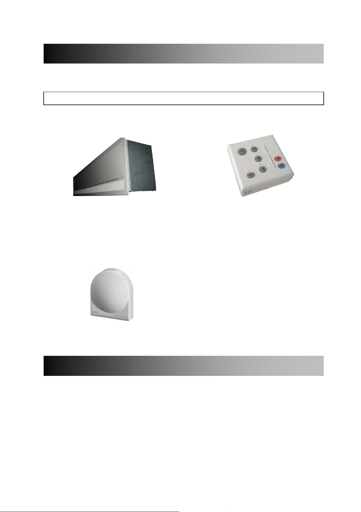
5. DELIVERY CONTENTS
The following items are supplied in the box at delivery.
NOTE: If any parts are missing or damaged contact your place of purchase.
HX Recessed Air Curtain Ecopower Remote Control
Note: The recessed grille is Supplied with 6m control cable
packed separately.
Outdoor Air Sensor (Optional)
Available for weather compensation
control
6. TOOLS REQUIRED
The following tools are required for installation:
Flat blade screwdrivers
Pozi head screwdrivers
10mm spanner
Adjustable spanner
9901098-2-1 Page | 5
Electric drill
Ladders
Appropriate lifting equipment
Appropriate tools for cutting ceiling
aperture
7. INSTALLATION
The air curtain is designed to be recessed within ceiling voids or bulkheads with in a building and
located horizontally over a doorway. It must not be installed outside of the building.
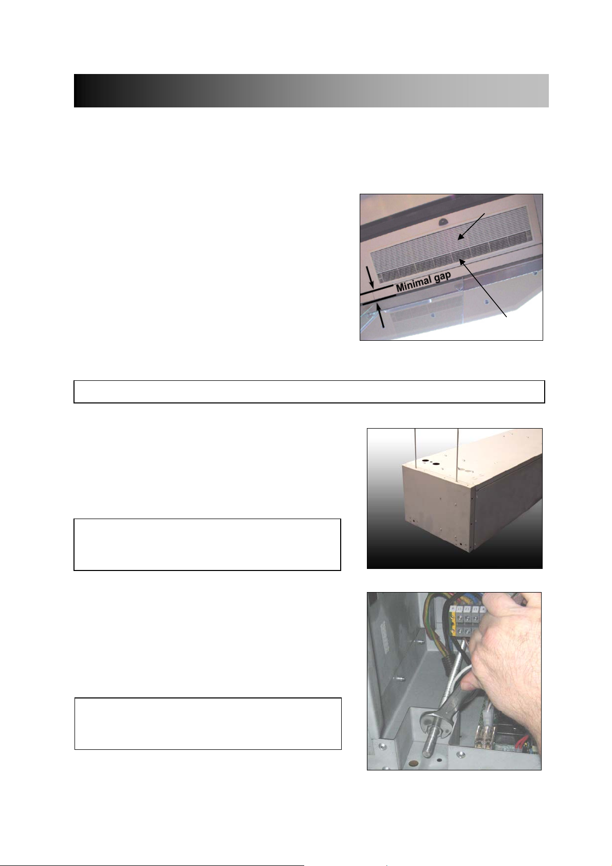
7.1 Location
Mount the air curtain above and as close to the doorway as
possible, with:
the recessed grille not more than 3.5m above floor
level
the air discharge (see 1, Fig 1) section of the
recessed grille nearest the doorway and the air inlet
section (see 2, Fig 1) furthest from the doorway
Beware of doorway top edges, structural beams, door
opening/closure devices, etc., which may interfere with
the air stream and affect the location of the unit.
Fig 1
2
1
NOTE: For the air curtain to work well the doorway should be less than the width of the airstream.
7.2 Ceiling Suspension
Step 1 Cut an aperture in the ceiling to the dimensions
in Appendix 1. Cut notches, if necessary, to clear
screws in the air curtain casing.
NOTE: For LPHW models, pipework will need to be
installed above the curtain. Allow sufficient access and
height clearance within the ceiling void to do this.
Step 2 Fix M10 threaded rods (not supplied) through
the 2 holes at each end in the top casing
(see Fig 2). Feed the rods through the casing and
attach to fixing brackets near the bottom of the
unit (see Fig 3, looking up into the air curtain). Use
M10 lock-nuts either side of the fixing bracket to
secure the hanging rod.
Fig 2
NOTE: Do not let these four hanging rods come below
the bottom of the unit casing or they may prevent the
recessed grille fitting properly.
9901098-2-1 Page | 6
Fig 3
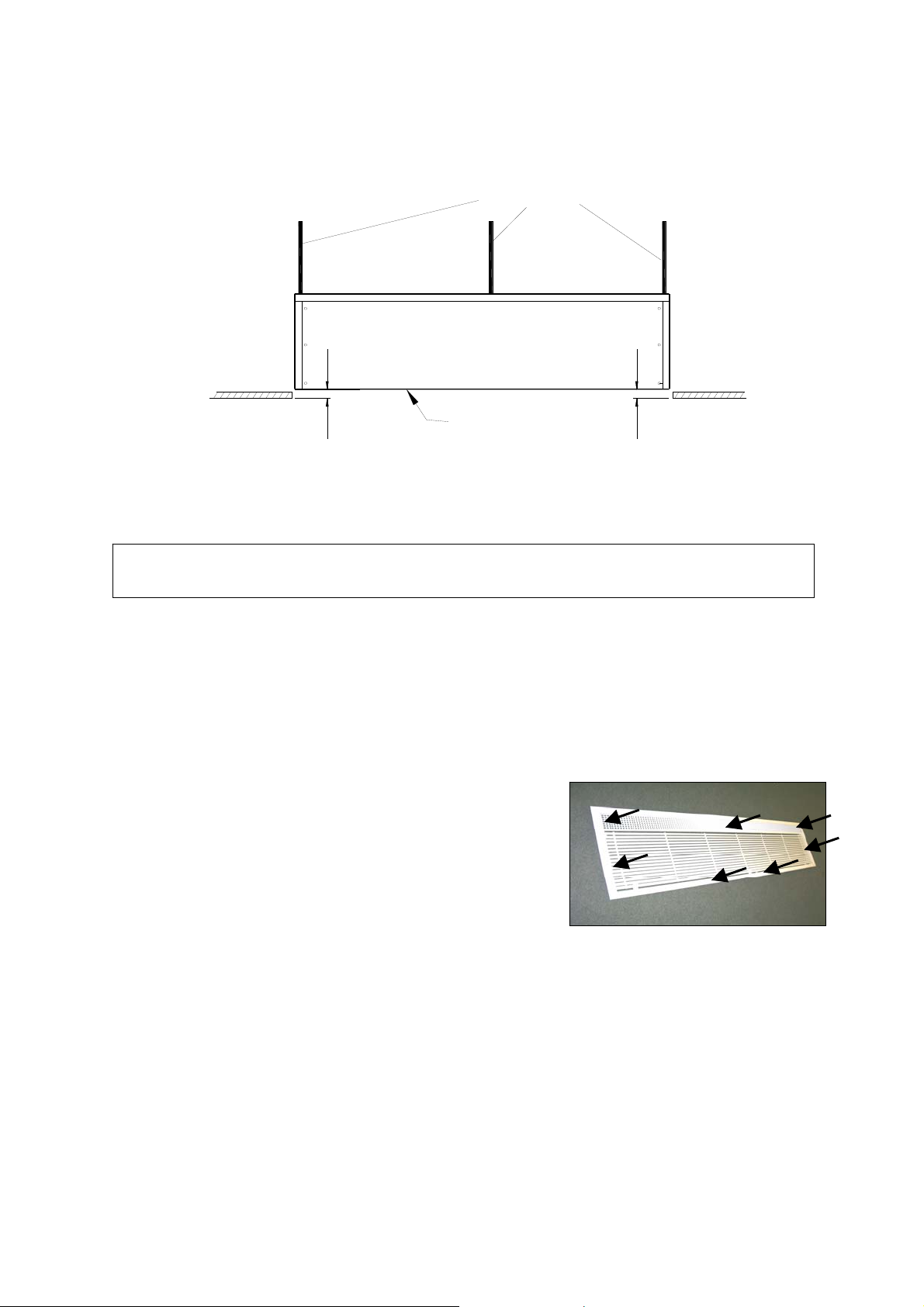
Step 3 If you are installing model HX1500R or HX2000R, fit a 5th M10 threaded rod into the
hanging point in the middle of the unit. Refer to Appendix 1 and Fig 4.
M10 hanging rods
Fig 4
RECESSED AIR CURTAIN
CEILING LEVEL CEILING LEVEL
38
Bottom surface of recessed
air curtain casing
38
Step 4 Secure each rod to a suitable structure that can support the weight of the unit (see
section 3: Specifications for weights).
WARNING: It is the sole responsibility of the installer to ensure that the fixing locations and
suspension system used are suitable for the air curtain being installed.
Step 5 Adjust the height of the unit on its hanging rods so the bottom surface of the casing goes
38mm up into the ceiling as shown in Fig 4. Ensure the unit is level.
7.3 Attaching the recessed grille to the air curtain
The recessed grille consists of:
Metal frame
Cellular discharge grille
Hinged inlet grille
There are 4 fixing points on the HX1000R, 6 on the HX1500R
and 7 on the HX2000R (see Fig 5).
Fig 5 (HX2000R shown)
9901098-2-1 Page | 7
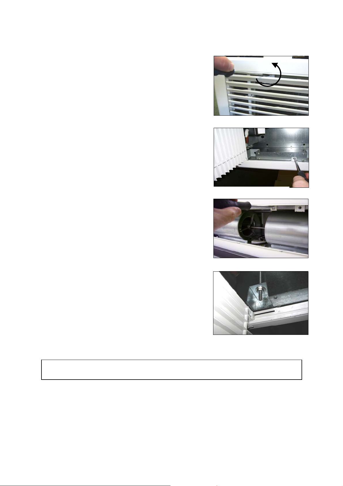
Fix the grille as follows:
Step 1 Open the hinged inlet grille using a flat bladed
screwdriver to release the quarter turn fasteners (see
Fig 6). There are two fasteners on the HX1000R unit
and three fasteners on HX1500R and HX2000R units.
Step 2 Make sure the grille will go the correct way around
(cellular discharge nearest to doorway). Offer the
recessed grille up through the cut-out in the ceiling
and attach it to the bottom of the air curtain casing
using M4 pozi head screws supplied. Start with
the screws shown in Fig 7 and then fit the two
at each end of the discharge grille.
Step 3 If fitting model HX1500R or HX2000R units insert 1 or
2 screws towards the middle of the unit as shown in
Fig 8.
Step 4 On model HX1500R or HX2000R units fit 1 screw in
the middle of the discharge grille. This screw is easier
to access if the hinged inlet grille is temporarily shut.
Step 5 With the hinged inlet grille open again adjust the
hanging rods (see Fig 9) so the grille frame fits neatly
against the ceiling. Ensure the grille frame is a snug fit
against the ceiling with no gaps all the way around.
Fig 6
Fig 7
Fig 8
Fig 9
NOTE: Open the hinged grille core to gain access to electrical connections, and for se rvicing and
maintenance.
9901098-2-1 Page | 8
 Loading...