

Thermoscreens HX Series, HX2000AR, HX1000WR, HX1500WR, HX1500AR Installation, Operation And Maintenance Instructions
...Page 1
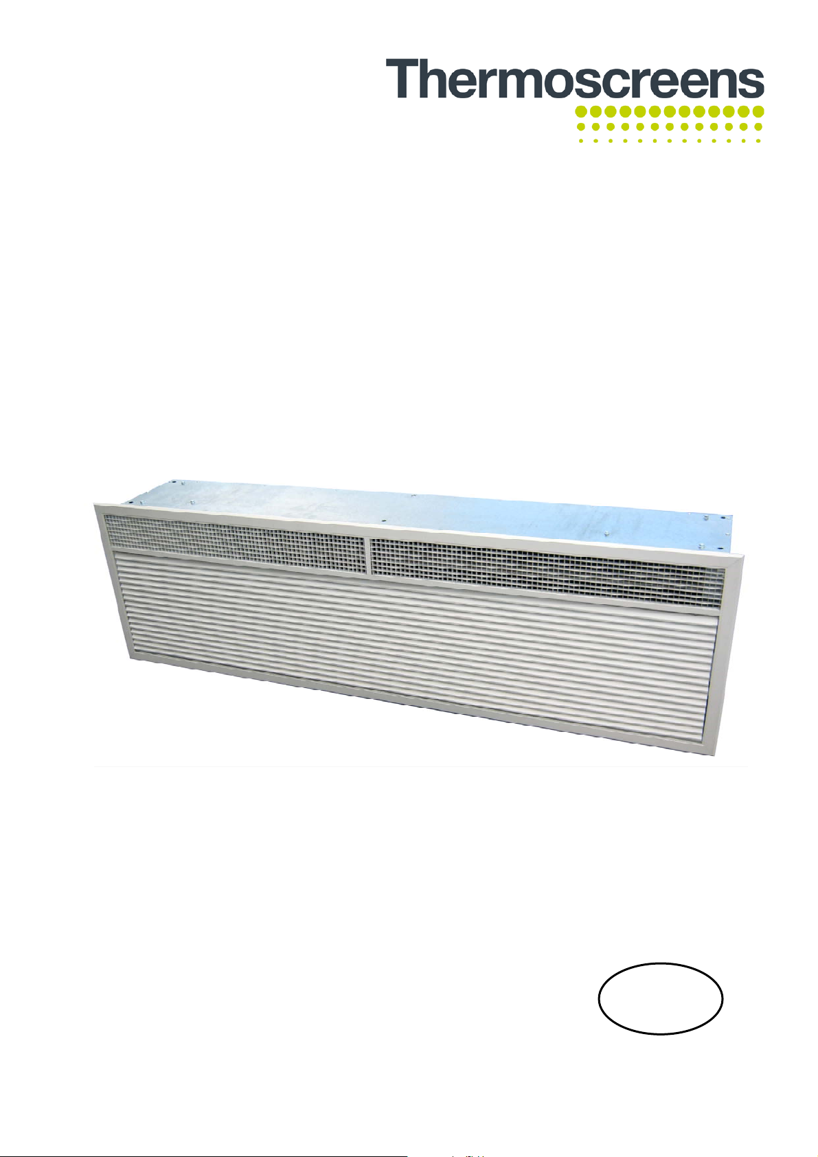
HX Series.
Recessed Range
9901098-2-1
INSTALLATION, OPERATION AND
MAINTENANCE INSTRUCTIONS
English
Page | 1
Page 2

1 CONTENTS
CONTENTS ...................................................................................................................................... 2
1
2 ELECTRICAL SAFETY ..................................................................................................................... 3
3 SPECIFICATIONS ............................................................................................................................ 3
4. INTRODUCTION .............................................................................................................................. 4
5. DELIVERY CONTENTS ................................................................................................................... 5
6. TOOLS REQUIRED .......................................................................................................................... 5
7. INSTALLATION ................................................................................................................................ 6
8. REMOTE CONTROL INSTALLATION ............................................................................................. 9
9. REMOTE CONTROL SETTINGS ..................................................................................................... 9
10. EXTERNAL CONTROLS ................................................................................................................ 10
11. SYSTEM CONFIGURATION .......................................................................................................... 11
12. MULTIPLE AIR CURTAINS ............................................................................................................ 12
13. FAN SPEED SELECTION .............................................................................................................. 13
14. REMOTE CONTROL OPERATION ................................................................................................ 14
15. COMMISSIONING THE SYSTEM .................................................................................................. 15
16. SIGN OFF ....................................................................................................................................... 15
17. FAULT CONDITIONS ..................................................................................................................... 16
18. SERVICE & MAINTENANCE ......................................................................................................... 17
19. WARRANTY ................................................................................................................................... 18
APPENDIX 1 — DIMENSIONS OF HX RECESSED AIR CURTAIN ....................................................... 19
APPENDIX 2A — WIRING DIAGRAM -HX1000ER ................................................................................. 20
APPENDIX 2B — WIRING DIAGRAM HX1500ER .................................................................................. 21
APPENDIX 2C — WIRING DIAGRAM HX2000ER .................................................................................. 22
APPENDIX 2D — WIRING DIAGRAM HX1000WR, HX1500WR and HX2000WR ................................. 23
APPENDIX 2E — WIRING DIAGRAM HX1000AR, HX1500AR and HX2000AR .................................... 24
20. DECLARATION OF CONFORMITY ............................................................................................... 25
9901098-2-1 Page | 2
Page 3

2 ELECTRICAL SAFETY
Electrical Supply and Wiring to the Air Curtain
All electrical wiring and connections MUST be carried out by a competent qualified electrici an in
accordance with the latest edition of the IEE wiring regulations and/or local statutory regulations.
A single phase or 3 phase local isolator having a contact separation of at least 3mm on all
poles must be fitted in the electrical supply to the air curtain and located in an accessible
position adjacent to the unit.
The appliance must be connected by cables having an appropriate heat resistant
temperature rating.
All supply cables, circuit breakers and other electrical installation equipment must be
correctly sized for the air curtain model being installed; see section 3: Specifications.
Models operating on 3 phase electrical supply - see section 3: Specifications - require a
neutral connection (3N~).
A 25mm size cable gland or conduit connector should be use d for the Electrical Supply
into the air curtain.
The air curtain must be earthed.
3 SPECIFICATIONS
Air Curtain
HX1000AR 230/1/50 0.2 0.8 – 1.10 45
HX1500AR 230/1/50 0.3 1.2 – 1.63 66
HX2000AR 230/1/50 0.35 1.4 – 2.15 80
HX1000WR 230/1/50 0.2 0.8 6/12 1.10 52
HX1500WR 230/1/50 0.3 1.2 9/18 1.63 75
HX2000WR 230/1/50 0.35 1.4 12/24 2.15 93
HX1000ER 400/3/50 12.2 18.2 6/12 1.10 46
HX1500ER 400/3/50 18.3 27.3 12/18 1.63 67
HX2000ER 400/3/50 24.35 36.2 12/24 2.15 84
Electrical
Supply
(V/ph/Hz)
Rated
Electrical
Power Input
(kW)
Rated
Current
per phase
(A)
Heat
Output
[Low/High]
(kW)
Effective
Width of
Airstream
(m)
Weight
(kg)
9901098-2-1 Page | 3
Page 4
4. INTRODUCTION
Established in the 1960s, Thermoscreens is a leading air curtain manufacturer that exports to over 60
countries worldwide.
As with all our products, the HX range of air curtains is designed with energy efficiency in mind.
HX models suffixed ER, WR or AR are designed to be recess mounted inside a building and located
horizontally over a doorway.
They must not be installed on the outside of a building.
Please complete the following details for your reference:
Date of Purchase
Place of Purchase
Serial Number
Proof of purchase is required to make a claim under warranty.
Thermoscreens Ltd
St. Mary’s Road
Nuneaton
Warwickshire
England
CV11 5AU
Email: [email protected] — www.thermoscreens.com
Tel: +44 (0) 24 7638 4646 — Fax: +44 (0) 24 7638 8578
9901098-2-1 Page | 4
Page 5
5. DELIVERY CONTENTS
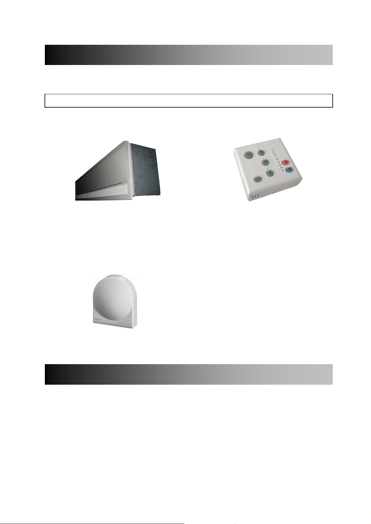
The following items are supplied in the box at delivery.
NOTE: If any parts are missing or damaged contact your place of purchase.
HX Recessed Air Curtain Ecopower Remote Control
Note: The recessed grille is Supplied with 6m control cable
packed separately.
Outdoor Air Sensor (Optional)
Available for weather compensation
control
6. TOOLS REQUIRED
The following tools are required for installation:
Flat blade screwdrivers
Pozi head screwdrivers
10mm spanner
Adjustable spanner
9901098-2-1 Page | 5
Electric drill
Ladders
Appropriate lifting equipment
Appropriate tools for cutting ceiling
aperture
Page 6
7. INSTALLATION
The air curtain is designed to be recessed within ceiling voids or bulkheads with in a building and
located horizontally over a doorway. It must not be installed outside of the building.
7.1 Location
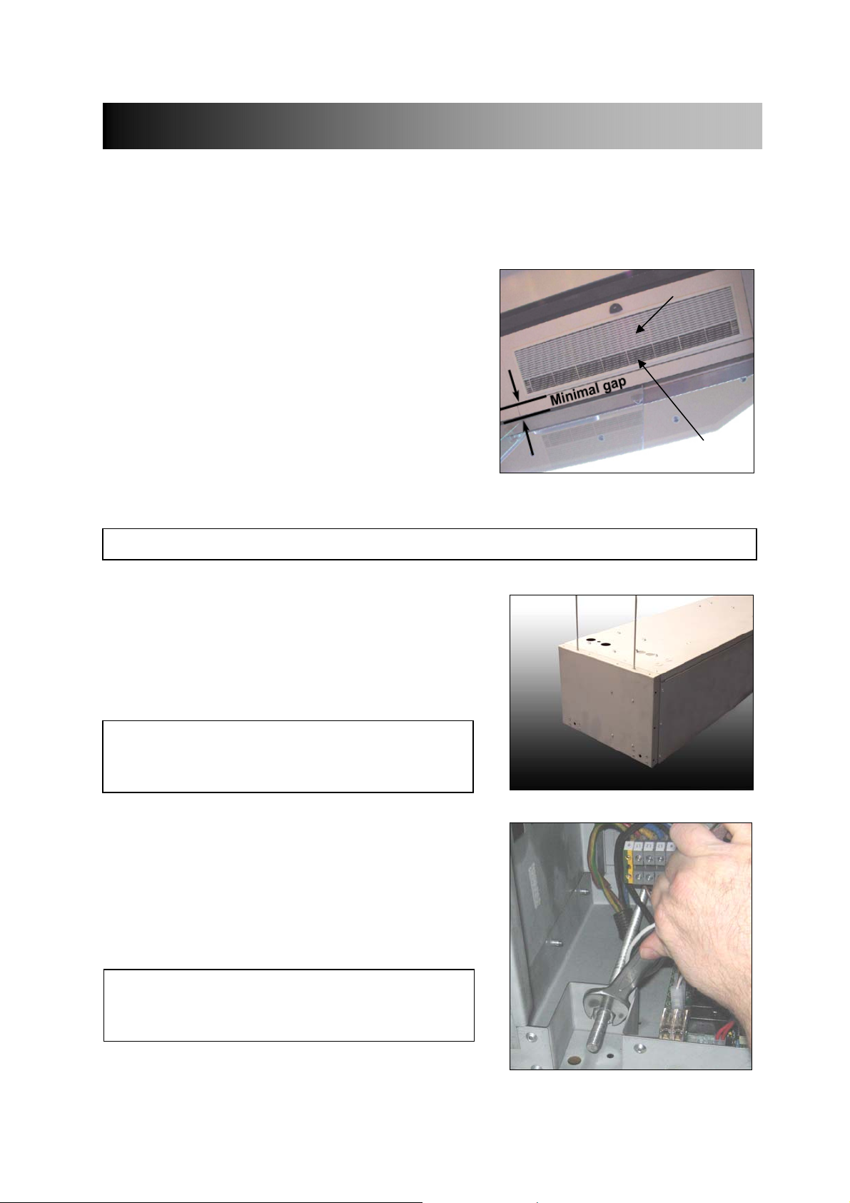
Mount the air curtain above and as close to the doorway as
possible, with:
the recessed grille not more than 3.5m above floor
level
the air discharge (see 1, Fig 1) section of the
recessed grille nearest the doorway and the air inlet
section (see 2, Fig 1) furthest from the doorway
Beware of doorway top edges, structural beams, door
opening/closure devices, etc., which may interfere with
the air stream and affect the location of the unit.
Fig 1
2
1
NOTE: For the air curtain to work well the doorway should be less than the width of the airstream.
7.2 Ceiling Suspension
Step 1 Cut an aperture in the ceiling to the dimensions
in Appendix 1. Cut notches, if necessary, to clear
screws in the air curtain casing.
NOTE: For LPHW models, pipework will need to be
installed above the curtain. Allow sufficient access and
height clearance within the ceiling void to do this.
Step 2 Fix M10 threaded rods (not supplied) through
the 2 holes at each end in the top casing
(see Fig 2). Feed the rods through the casing and
attach to fixing brackets near the bottom of the
unit (see Fig 3, looking up into the air curtain). Use
M10 lock-nuts either side of the fixing bracket to
secure the hanging rod.
Fig 2
NOTE: Do not let these four hanging rods come below
the bottom of the unit casing or they may prevent the
recessed grille fitting properly.
9901098-2-1 Page | 6
Fig 3
Page 7
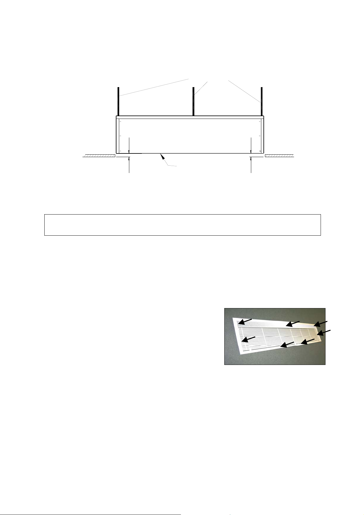
Step 3 If you are installing model HX1500R or HX2000R, fit a 5th M10 threaded rod into the
hanging point in the middle of the unit. Refer to Appendix 1 and Fig 4.
M10 hanging rods
Fig 4
RECESSED AIR CURTAIN
CEILING LEVEL CEILING LEVEL
38
Bottom surface of recessed
air curtain casing
38
Step 4 Secure each rod to a suitable structure that can support the weight of the unit (see
section 3: Specifications for weights).
WARNING: It is the sole responsibility of the installer to ensure that the fixing locations and
suspension system used are suitable for the air curtain being installed.
Step 5 Adjust the height of the unit on its hanging rods so the bottom surface of the casing goes
38mm up into the ceiling as shown in Fig 4. Ensure the unit is level.
7.3 Attaching the recessed grille to the air curtain
The recessed grille consists of:
Metal frame
Cellular discharge grille
Hinged inlet grille
There are 4 fixing points on the HX1000R, 6 on the HX1500R
and 7 on the HX2000R (see Fig 5).
Fig 5 (HX2000R shown)
9901098-2-1 Page | 7
Page 8
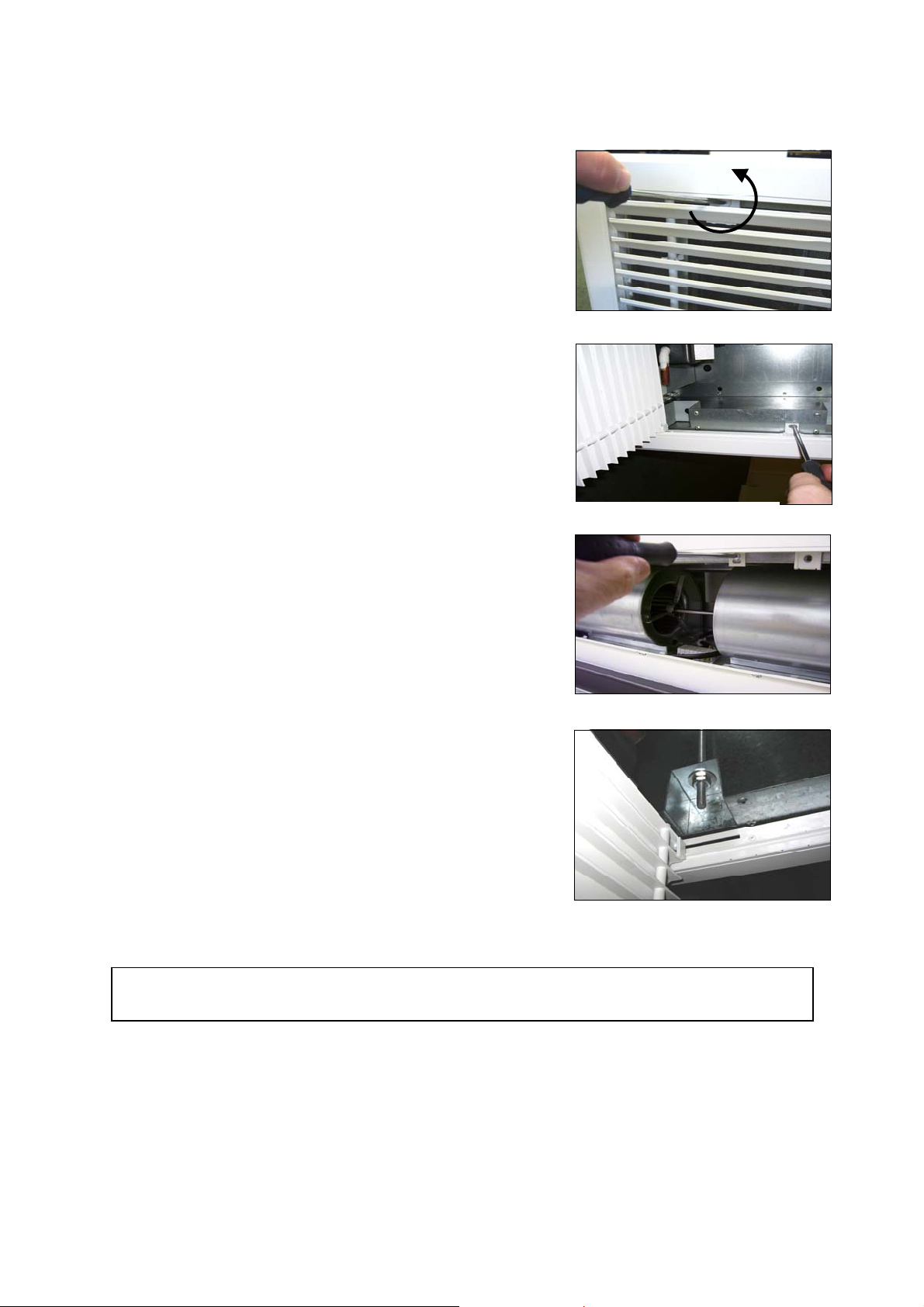
Fix the grille as follows:
Step 1 Open the hinged inlet grille using a flat bladed
screwdriver to release the quarter turn fasteners (see
Fig 6). There are two fasteners on the HX1000R unit
and three fasteners on HX1500R and HX2000R units.
Step 2 Make sure the grille will go the correct way around
(cellular discharge nearest to doorway). Offer the
recessed grille up through the cut-out in the ceiling
and attach it to the bottom of the air curtain casing
using M4 pozi head screws supplied. Start with
the screws shown in Fig 7 and then fit the two
at each end of the discharge grille.
Step 3 If fitting model HX1500R or HX2000R units insert 1 or
2 screws towards the middle of the unit as shown in
Fig 8.
Step 4 On model HX1500R or HX2000R units fit 1 screw in
the middle of the discharge grille. This screw is easier
to access if the hinged inlet grille is temporarily shut.
Step 5 With the hinged inlet grille open again adjust the
hanging rods (see Fig 9) so the grille frame fits neatly
against the ceiling. Ensure the grille frame is a snug fit
against the ceiling with no gaps all the way around.
Fig 6
Fig 7
Fig 8
Fig 9
NOTE: Open the hinged grille core to gain access to electrical connections, and for se rvicing and
maintenance.
9901098-2-1 Page | 8
Page 9
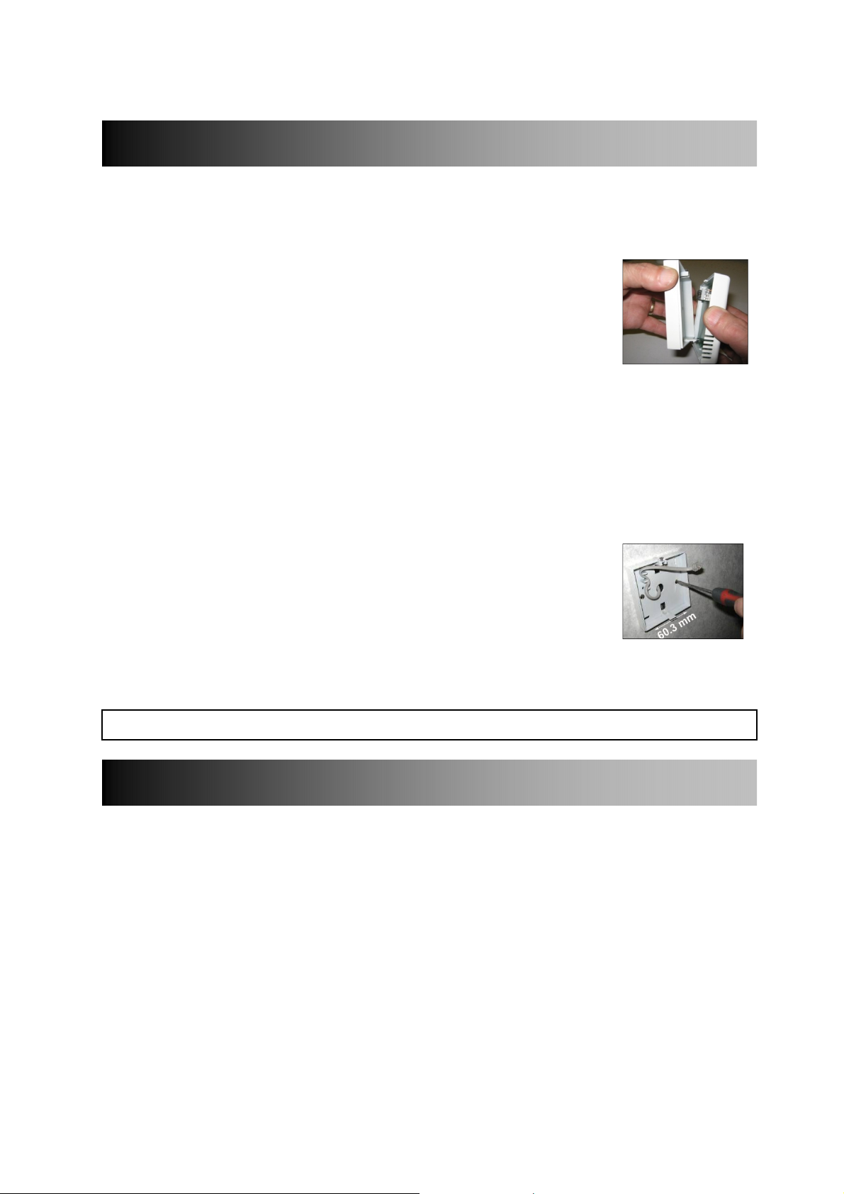
8. REMOTE CONTROL INSTALLATION
Mount the remote control unit in a convenient position directly to the wall or onto a switch box.
8.1 Wall mounting
Step 1 Using a screwdriver undo the screw on the top of the remote
control case and pull the back case away (see Fig 10).
Step 2 Feed one end of the RJ control cable through the back case, secure it,
then screw the back case to the wall using suitable fixings (not supplied).
Step 3 Connect the RJ plug to the RJ socket on the PCB.
Step 4 Refit the front case.
8.2 Switch box mounting
Step 1 Using a screwdriver undo the screw on the top of the remote
control case and pull the back case away (see Fig 10).
Step 2 Feed one end of the RJ control cable through the switch box, feed and
secure the RJ control cable through the back case and secure ba ck
case to switch box using 2 x M3.5 screws (not supplied) (see Fig 11).
Step 3 Connect the RJ plug to the RJ socket on the PCB.
Step 4 Refit the front case.
Fig 10
Fig 11
NOTE: For optional remote control settings, see section 9.
9. REMOTE CONTROL SETTINGS
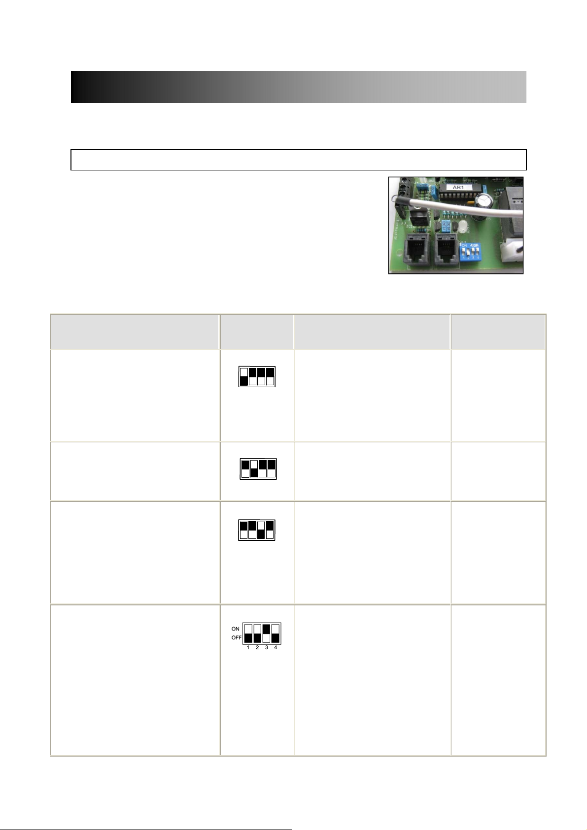
On the back of the remote controller PCB you will find four DIP switches that provide the following
optional features.
DIP1 – Reset on power-up
On restoring power after an electrical
interruption all remote control settings are
retained. DEFAULT SETTING ON
Dip2 – Stop fan on cold
Fans are switched off when heating level is
achieved (Automatic mode only).
DEFAULT SETTING OFF
9901098-2-1 Page | 9
DIP3 – Never blow cold
Air curtain always heats in Automatic mode
(i.e. will not go to ambient mode).
DEFAULT SETTING OFF
DIP4 – Room air temperature control
Enabling the room air sensor in the remote
control disables all other temperature sensors.
DEFAULT SETTING OFF
Page 10
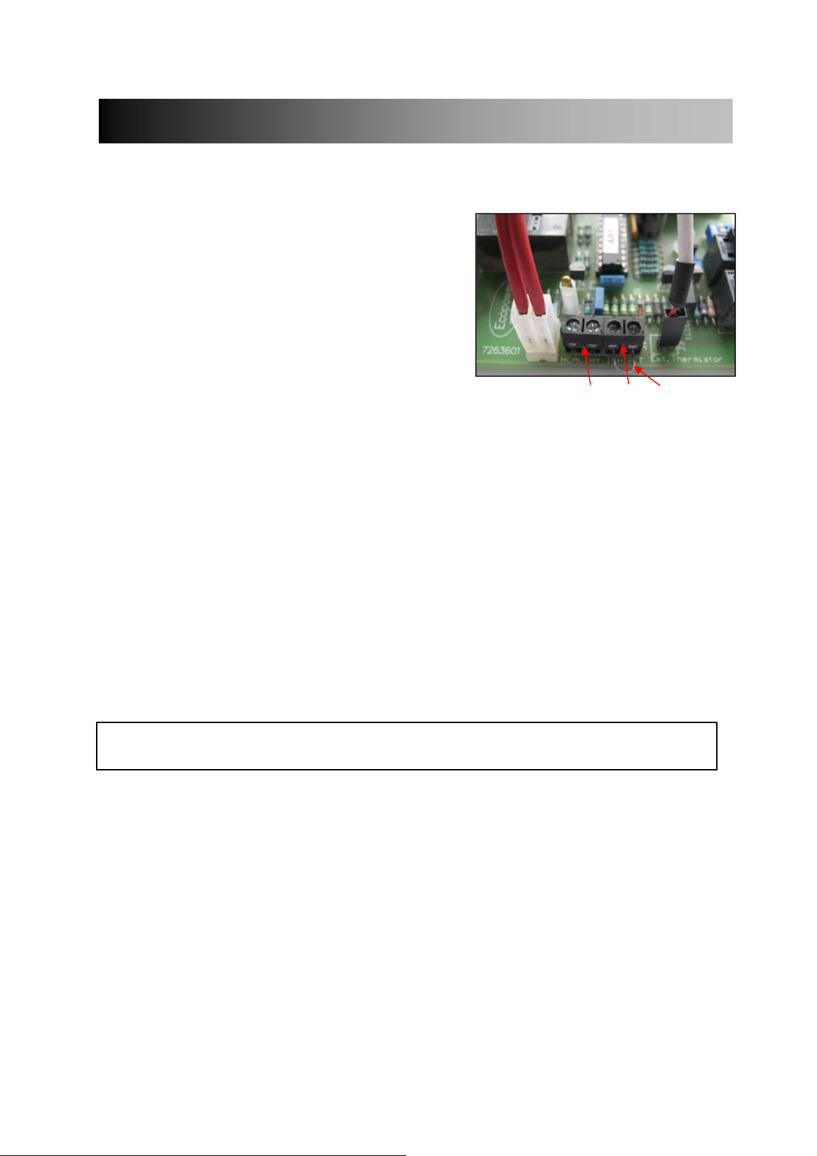
10. EXTERNAL CONTROLS
10.1 BMS remote on/off
To enable the system to be used with BMS remote
switching, an INHIBIT two way screw terminal is fitted on
the air curtain motherboard (see 2, Fig 12).
To allow the unit to run, use 2 wires to link the terminal to a
remote volt free contact.
To switch the unit off, leave terminals disconnected (open
circuit).
In a master/slave arrangement consisting of several air curtains, connect the remote contact to any
one of the air curtains. All units will then turn on and off.
At factory setting a wire link is fitted to the INHIBIT terminal (see 3, Fig 12). For summer operation
connect a 3.3kΩ resistance across the INHIBIT terminal and only the fans will run, without heat, even
if the remote controller is calling for heat.
Fig 12
1 2
3
10.2 Overheat cut-out indication
The air curtain motherboard includes a HEALTHY two way screw terminal (see 1, Fig 12) to provide a
fault signal indication if the electric heater overheat cut-out operates (electric heated air curtains only).
A healthy system provides a 24V DC signal at the terminals. An overheat cut-out fault will be 0V DC
at the terminals.
WARNING: Do not apply any other voltage to the INHIBIT and HEALTHY terminals as damage to
the Ecopower motherboard will occur.
10.3 Weather compensation
For Weather Compensation Heat Control, fit an outside air temperature sensor (Specification - 10k
NTC sensing element, time constant 14 minutes and IP54 protection, or optional Siemens QAC2030).
Use a 2-core cable to connect the outdoor air temperature sensor to air curtain terminals 1 and 2 on
the connector terminal block on electric heated units (see wiring diagrams, Appendix 2A, 2B, 2C), or
terminals 5 and 6 on water heated units (see wiring diagram, Appendix 2D).
Set DIP switches 2 and 4 to the ON position on the Ecopower motherboard (see section 11: System
Configuration). For Master/Slave multiple installations, this must be the Thermostat Master unit.
9901098-2-1 Page | 10
Page 11
11. SYSTEM CONFIGURATION
11.1 Optional features
WARNING: Isolate and disconnect air curtain from the power source before making any changes.
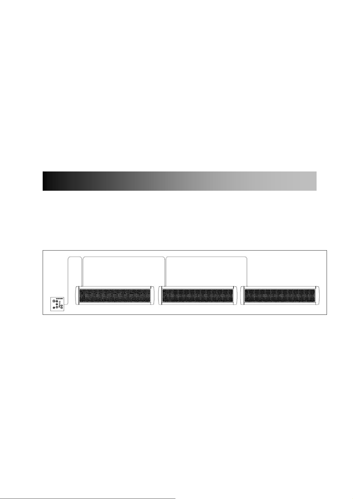
DIP switches fitted to the air curtain motherboard (see Fig 13) provide
the following optional features, as explained below:
Fan heat interlock
Disable fan run-on
Thermostat master for master/slave installations
Weather compensation heat control
Function
Fan heat interlock
Allows fan speed to govern heat
output on electric heated units.
If low or medium fan speed is
selected, a lower heat output
results. High heat operates only on
high fan speed.
Disable fan run-on
The 2 minute fan run-on after
switch off is enabled or disabled on
electric heated air curtains.
Thermostat master
For master/slave installations. Only
the air sensor thermistor in the
thermostat master air curtain will be
used for measuring air temperature.
Set DIP switch 1 to ON in the air
curtain that will be the master unit.
Weather compensation heat
control
Enables heat output of air curtain to
vary with outside temperature.
Set DIP switches 2 and 4 to ON to
enable.
See Note 1 below.
Control
DIP1
ON
OFF
1 2 3 4
DIP2
ON
OFF
1 2 3 4
DIP3
ON
OFF
1 2 3 4
DIP2 & 4
DIP1 shown
ON for fan
heat interlock.
Set DIP3 to
ON in master/
slave
installations.
Comments
This function applies to electric
heated air curtains only to limit
high air temperatures.
Set DIP1 to OFF if unit is water
heated or ambient.
Must only be used for LPHW
and Ambient air curtains. Each
air curtain must have DIP2 set to
ON for no fan run-on.
Air sensor thermistors in all
slave air curtains will be ignored.
Avoids some units blowing cold
air and others blowing warm air
in master/slave arrangements on
larger doorways.
If enabled, connect a suitable
outside air temperature sensor
(e.g. Siemens QAC2030) to the
air curtain terminal block (see
section 10.3: Weather
compensation).
See Note 2 below for weather
compensation heat control
strategy.
Fig 13
Factory Setting
ON
Heat output is
governed by fan
speed.
OFF
Run-on enabled.
OFF
Air sensors on
multiple
installations
measure and act
independently
OFF
Weather
compensation not
active.
9901098-2-1 Page | 11
Page 12
Note 1
See section 10.3: Weather compensation for details of outside air temperature sensor and wi ring to
the air curtain.
Set DIP switch 2 and 4 to the ON position in the air curtain that has the outdoor air temperature
sensor wired into it. For Master/Slave multiple installations this must be the Thermostat Master unit.
Note 2
When remote controller is set to automatic the outdoor air temperature determines the heat output as
follows:
Less than 10°C, full heat operates.
Between 10 and 15°C, half-heat operates.
More than 15°C, no heat operates
12. MULTIPLE AIR CURTAINS
When controlling multiple air curtains in a master/slave arrangement, plug the remote controller into
any one of the units.
Connect this unit to other unit(s) with a Thermoscreen RJ extension lead (not supplied), as per the
diagram below. Each air curtain must have its own electrical supply.
9901098-2-1 Page | 12
Page 13
13. FAN SPEED SELECTION
If required, select fan speed at commissioning to suit outdoor environmental conditions and indoor
noise levels.
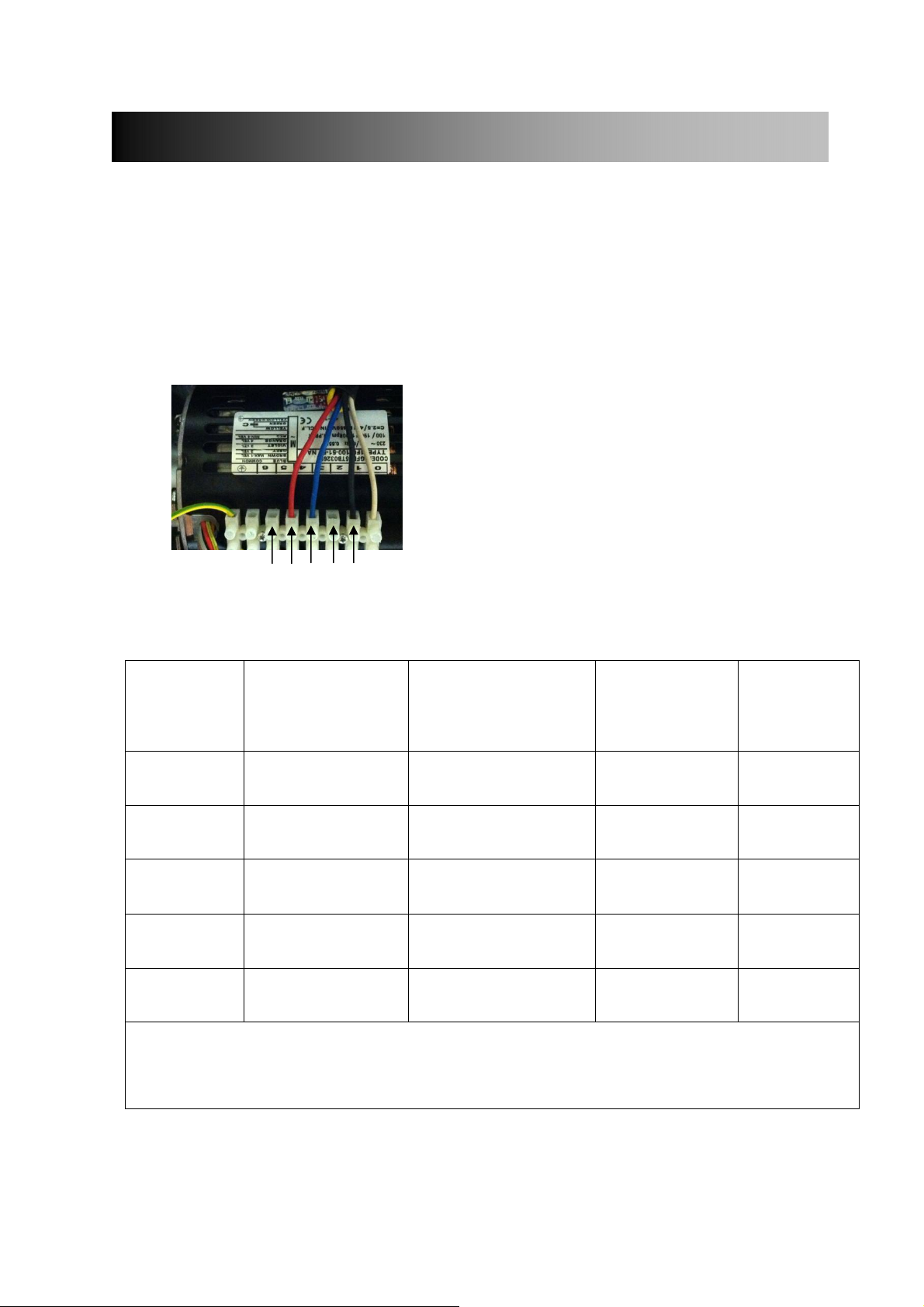
Factory settings for the 3 fan speeds are as follows:
HIGH fan speed (black wire) is wired into motor tapping 1 (highest motor speed tapping)
MEDIUM fan speed (blue wire) is wired into motor tapping 3
LOW fan speed (red wire) is wired into motor tapping 4
motor tapping: 5 4 3 2 1
Set fan speeds according to the following table.
Fan Speed
(air curtain as
delivered)
HIGH
(black wire)
Motor Speed
Tapping
1 – (highest speed)
Maximum air curtain
mounting height
(m)
3.5
Sound Pressure
Level of air
curtain
[dB(A) at 3m]
HX1000 - 58
HX1500 - 58
HX2000 - 58
2
3.2
HX1000 - 57
HX1500 - 55
HX2000 - 57
MEDIUM
(blue wire)
3
2.8
HX1000 - 55
HX1500 - 54
HX2000 - 55
LOW
(red wire)
4
2.3
HX1000 - 51
HX1500 - 50
HX2000 - 51
5 – (lowest speed)
2.0
HX1000 - 48
HX1500 - 45
HX2000 - 48
Sound pressure levels dB(A) at 3m distance are for a single air curtain mounted at its maximum mounting height, operating in a
room with average acoustic characteristics as defined in CIBSE Guide B5 (reverberation time 0.7s at 1kHz) and a room size
equivalent to 8 air changes per hour (ac/h). Care needs to be taken when selecting air curtains for an installation as noise levels
can be several dB higher if the mounting height is reduced, if the room is more ‘live’ (i.e. hard surfaces, no furnishings or
absorbent materials), if the room is smaller than 8 ac/h equivalent or a combination of these factors. Noise levels will also increase
if more than one air curtain is installed at the same doorway (e.g. +3dB(A) for 2 equal point sources: direct field).
Air Volume
Flow Rate
3
(m
1370
2000
2640
1315
1810
2545
1220
1700
2390
1060
1395
2095
930
1135
1890
/h)
9901098-2-1 Page | 13
Page 14
14. REMOTE CONTROL OPERATION
7
1
Heating level
scale
6
4
2
3
5
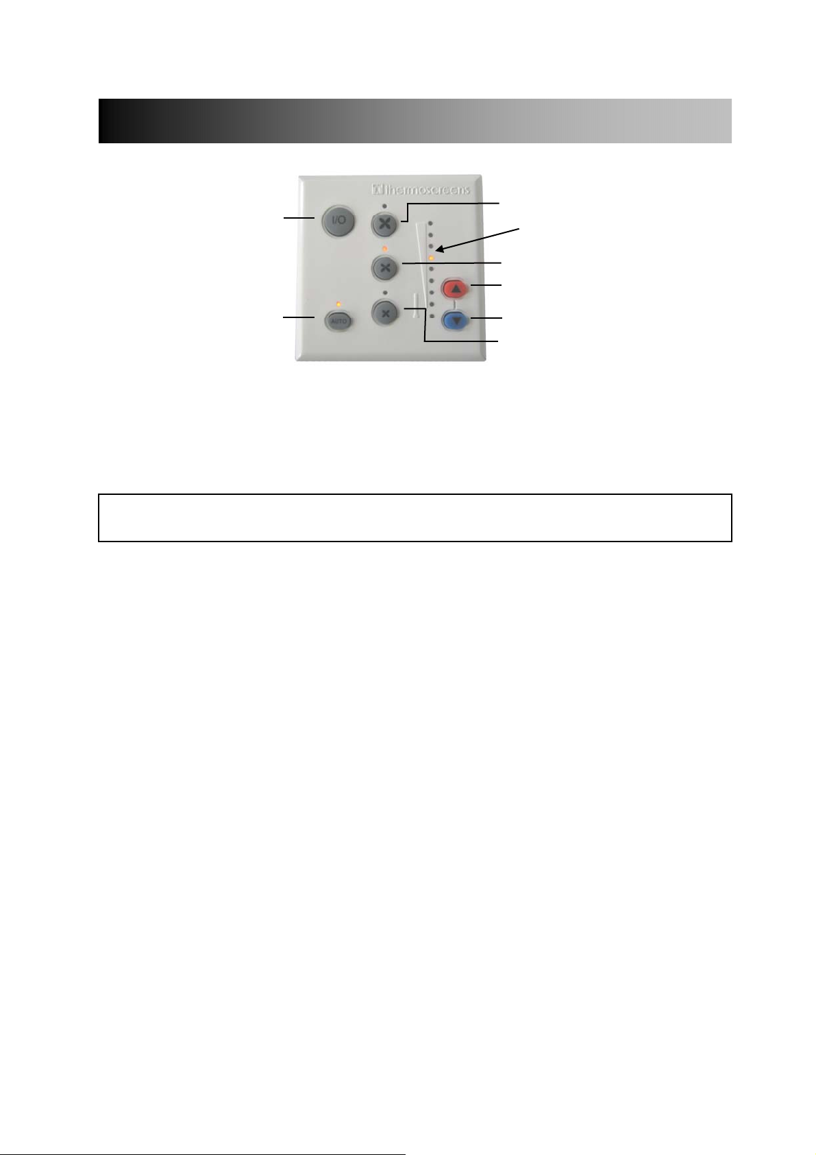
Use the remote control to operate the air curtain as follows:
1 On/Off
Turns the air curtain On or Off.
NOTE: If an electric heated air curtain is heating when switched off the fan will run-on for
approximately 2 minutes to dissipate excess heat.
2 Manual/Automatic
Switches between Manual and Automatic modes.
The Auto On indicator LED is lit for "Auto Mode" and unlit for "Manual Mode".
3 & 4 Heating level controls
Manual mode
Select heating level from zero, to half heat, to full heat by stepping up or down with the heating level
controls. The heating level scale shows the level selected.
Automatic mode
Heat output is controlled automatically according to:
Room air temperature
Incoming air temperature, or
External air temperature
This is dependent on the settings made in Section 11: System Configuration (DIP switches 2 and 4),
and Section 8: Remote Control Settings (DIP switch 4).
5, 6 & 7 Fan speed
Switch fan speed between Low, Medium and High respectively. The appropriate LED illuminates.
9901098-2-1 Page | 14
Page 15

15. COMMISSIONING THE SYSTEM
15.1 Verify system operation
To commission the system, verify the following conditions are met:
All fans are working.
Fans operate at Low, Medium and High speeds.
There is no excessive mechanical noise coming from the fans.
When heating is selected, the air stream from the discharge grille warms up across the whole
length of the air curtain.
When set to manual with fans set to high speed, heating increases as higher heat is selected.
Warm air reaches across the doorway with door open or closed.
Ecopower remote controller operates correctly in both manual and auto modes.
15.2 Instruct operator and hand over
Before leaving site, hand over the installation to the end user or their representative.
Recommend that any person operating the air curtain be given adequate instruction and supervision
by a person responsible for their safety. Children and those with reduced physical, sensory or mental
capabilities should not operate the air curtain.
Recommend that the doorway should be closed whenever possible.
Recommend that during times of high pedestrian use it will become an ‘open doorway’. The air
curtain then serves an essential purpose by saving energy and providing comfort to occupants.
Explain that the inlet grilles and air filters (if fitted) must be cleaned regularly and the unit serviced at
schedule intervals – see section 18: Service & Maintenance.
16. SIGN OFF
Complete the following once commissioning is completed.
Installer signature: _________________________________________
Installer name: _____________________________________________
Company name: _____________________________________________
Date: _____________________________________________________
9901098-2-1 Page | 15
Page 16

17. FAULT CONDITIONS
17.1 Thermal cut-out
An overheat fault in electric heated units may cause the thermal cut-out trip(s) to operate.
This is indicated by flashing LEDs on the remote control and a red status LED on the air curtain
motherboard.
Before resetting ensure there is adequate air flow from the air curtain and the unit has been
commissioned as per section 15.
To reset a thermal cut-out trip:
Step 1 Switch off the electrical supply to the air curtain.
Step 2 Allow time for the air curtain to cool down, typically 10 minutes.
Step 3 Switch on the electrical supply to the air curtain.
Step 4 Press the Auto button on the remote control 4 times.
Air curtain heaters will then operate and after 30 seconds the LEDs on the remote control will stop
flashing and the status LED will flash green.
17.2 Fuses
In the event of an electrical fault internal electrical fuses may operate.
There are two internal fuses located on the motherboard inside the air curtain:
Fuse 6.3A (T) supplies the fan motors within the air curtain
Fuse 125mA (F) controls the operation of the motherboard
17.3 PCB status indication
LED1 on the air curtain motherboard is a status LED (See LED1 on Appendices, Wiring Diagrams).
This indicates the status of the Ecopower Control system as follows:
1. LED flashing green – operation normal
2. LED flashing red – low supply voltage or controller not plugged into motherboard
3. LED permanently red – thermal cut-outs open circuit from an overheat situation (see
Section 17, Fault Conditions for how to reset)
4. LED flashing alternate red/green – air curtain configured for Weather Compensation
Control (DIP 2 and 4 ON) but no outdoor air sensor is connected to Ecopower PCB.
Remote Control LEDs will also flash to indicate a connection error.
9901098-2-1 Page | 16
Page 17
18. SERVICE & MAINTENANCE
WARNING: Failure to adequately maintain the unit and provide a suitable cleaning schedule will
result in performance degradation, reduction in life expectancy of the air-curtain and possible
overheating and fire risk with electric heated units
18.1 Every week
NOTE: Weekly maintenance can be carried out by the Cleaner or Janitor from floor level.
Turn off the air curtain to prevent dust entry, then clean the face of the air inlet grille and air filter
inside the grille using a vacuum cleaner with an extension tube and brush.
18.2 Every 3 months
WARNING: Before servicing, isolate and disconnect the air curtain from the power source.
WARNING: The following servicing, maintenance must be carried out by a competent electrician or
a Thermoscreens appointed technician.
Clean and inspect the inside of the air curtain as follows:
Step 1 Open the hinged inlet grille using a flat bladed screwdriver to release the quarter turn
fasteners (see Fig 6, Section 7.3).
Step 2 Clean and remove any build-up of dust and dirt within the air-curtain (inlet/outlet grilles,
fan impellers, housings and motors) using a vacuum cleaner and soft brush.
NOTE: Build-up of dirt on fan impellers can cause vibration, noise and excessive wear on the
motor bearings.
Step 3 Check within the unit to ensure all electrical connections and crimped terminals are tight.
Step 4 On electric heated air curtains, remove the fan deck(s) as follows to inspect electric
heaters, electrical wiring and connections and to remove dust, dirt and debris:
Unclip the fan motor electrical connector.
Unfasten 4 x M6 nuts/bolts on each fan deck.
Unfasten M4 screws at bottom edge of fan deck.
Carefully lift the fan deck away from the air curtain.
Refit fan deck(s) and close the hinged air inlet grille after servicing. Reconnect electrical supply and
test to ensure correct operation (see Section 15: Commissioning).
9901098-2-1 Page | 17
Page 18

19. WARRANTY
All units are covered by a two year warranty.
If any problems are encountered, please contact your installer/supplier.
Failing this please contact the Thermoscreens warranty department.
Care has been taken in compiling these instructions to ensure they are correct. Therm oscreens Ltd.
disclaims all liability for damage resulting from any inaccuracies and/or deficiencies in this
documentation. Thermoscreens Ltd. retain the right to change the specifications stated in these
instructions.
Thermoscreens Ltd Email: [email protected]
St. Mary’s Road Nuneaton Tel: + 44 (0) 24 7638 4646
Warwickshire England Fax: + 44 (0) 24 7638 8578
CV11 5AU www.thermoscreens.com
9901098-2-1 Page | 18
Page 19
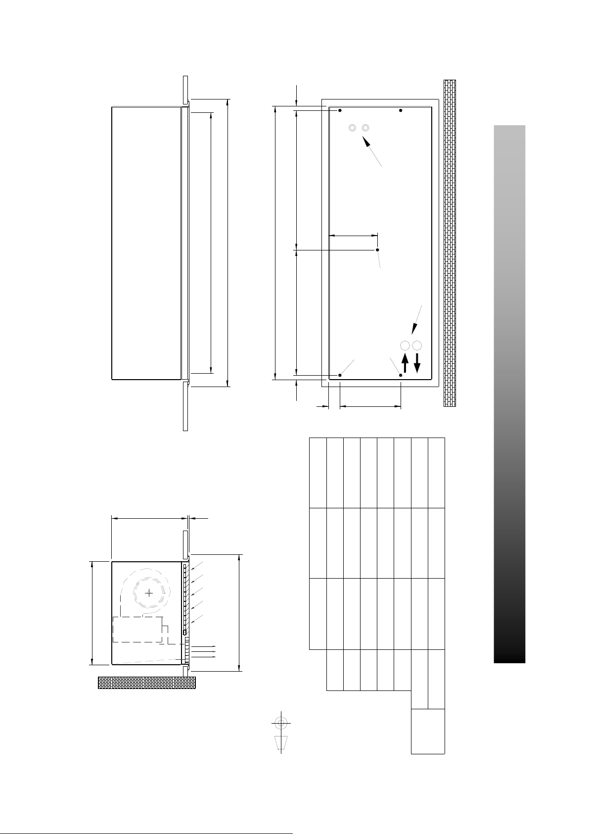
2525
C
supply and controls
Entry points for electrical
200
D
E (Effective Width of Airstream)
A
LPHW connections
Rp¾
B
4 for 1m unit,
5 for 1.5m & 2m units
Holes for M10 drop rods
Use all drop rod holes !
65 265
CEILING LEVEL
348
6
933
726 1077
485 485
HX1500R HX2000R
-
485
539
1185 1710 2235
-1109
1100 1630 2150
1238 1763 2290
485
1185 1710 2235
HX1000R
APPENDIX 1 — DIMENSIONS OF HX RECESSED AIR CURTAIN
A (mm)
C (mm)
B (mm)
9901098-2-1 Page | 19
E (mm)
D (mm)
Width (mm)
Length (mm)
Cut-Out
in Ceiling
Page 20
1.0 kW (x3) 1.0 kW (x3)
1.0 kW (x3) 1.0 kW (x3)
*s *s
*s *s
*s *s
*s - star point connection:
2nd Stage - 2.5mm² Grey tri-rated cables
1st Stage - 2.5mm² Black tri-rated cables
First Stage Heating Second St age Heating
1~
Fan Motor 1
Orange
Violet
Brown (High)
Blue (Neutral)
0
White
Black
Yellow
White
Brown
K1
F1 = 6.3A (T)
F2 = 125mA (F)
F1 F2
Red
Grey
Brown
Black
Blue
Thermal Trip
85°C H11 Auto
J2
J3
K3
Live 1 K2
HEALTHY
INHIBIT
White
K4
LED 1
ON
1234
Black
Yellow
K6
Live 2 K5
Fan
High speed
Medium speed
Yellow
White
Grey
K7
2
Motor
Low speed
Neutral
Live 3 K8
K9
High speed
Blue
Neutral K10
1
Fan
Motor
Medium speed
Low speed
Neutral
ECOPOWER CONTROLLER - CVR 1008
1
Grey
234
Red (Low)
5
Blue
Red
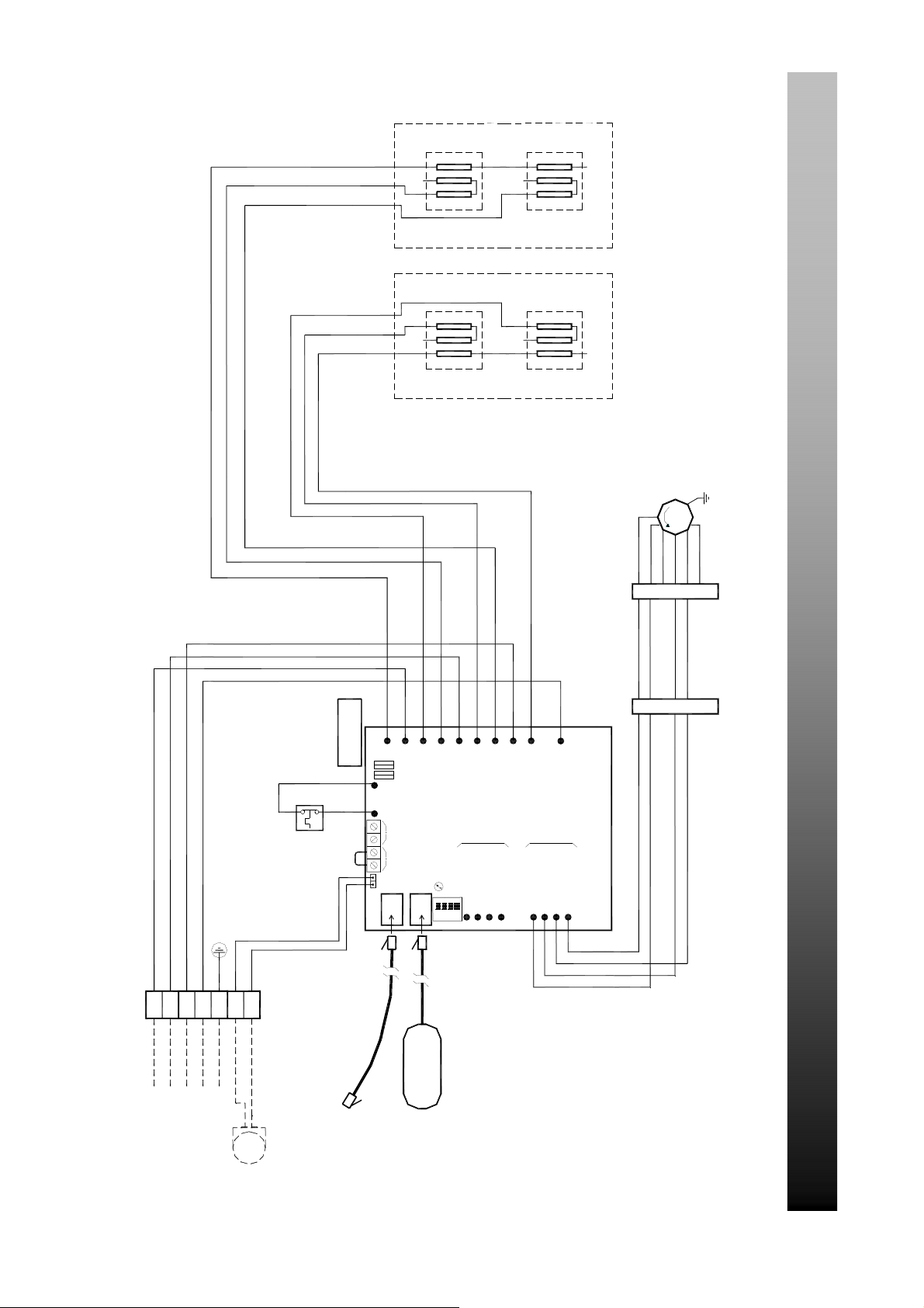
APPENDIX 2A — WIRING DIAGRAM -HX1000ER
White
Black
Blue
Red
e
l
b
L2
L2
L3
L3
N
E
N
L1
BLOCK
TERMINAL
L1
1
2
E
To Slave
400V / 3ph / 50Hz
External Air
Sensor
a
C
e
v
a
l
S
/
r
e
t
s
a
M
REMOTE
CONTROL
Air Curtain
9901098-2-1 Page | 20
Page 21
1.0 kW (x2) 1.0 kW (x2) 1.0 kW (x2)
*s
A1
A2
13NO
14NO
Yellow
6
5
3
1
Yellow
4
230V AC Coil
Yellow
CONTACTOR
2
1.0 kW (x4) 1.0 kW (x4) 1.0 kW (x4)
*s *s
*s *s *s
*s *s *s
*s - star point connection:
2nd Stage - 2.5mm² Grey tri-rated cables
1st Stage - 2.5mm² Black tri-rated cables
First Stage Heating Second Stage Heating
1~
Fan Motor 1
Orange
Violet
Brown (High)
Blue (Neutral)
012
Blue
Grey
Brown
Black
Grey
Black
Brown
Blue
White
Black
Grey
345
Blue
Red (Low)
Red
TERMINAL
BLOCK
400V / 3ph / 50Hz
L1
L1
L2
L2
L3
L3
White
Yellow
Red
White
Brown
K1
F1 = 6.3A (T)
F2 = 125mA (F)
F1 F2
J2
(x2)
Thermal Trip
85°C H11 Auto
J3
Live 1 K2
K4
K3
HEALTHY
INHIBIT
LED 1
ON
1234
White
Black
Live 2 K5
Grey
K6
K7
2
Fan
Motor
Medium speed
Low speed
High speed
Neutral
Live 3 K8
Blue
K9
Neutral K10
1
Fan
Motor
Medium speed
Low speed
High speed
Neutral
ECOPOWER CONTROLLER - CVR 1008
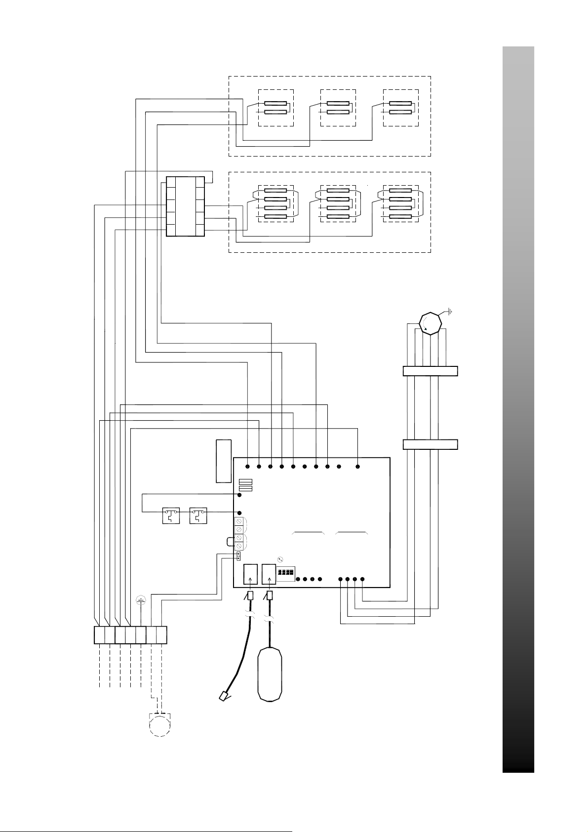
APPENDIX 2B — WIRING DIAGRAM HX1500ER
White
Black
Blue
Red
e
l
b
Air Curtain
a
C
e
v
a
l
S
/
r
e
t
s
a
M
REMOTE
CONTROL
1
2
E
N
E
N
To Slave
Sensor
External Air
9901098-2-1 Page | 21
Page 22
A1
A2
13NO
5
3
1
White
14NO
6
White
4
230V AC Coil
White
CONTACTOR
2
*s *s
1.0 kW (x3) 1.0 kW (x3) 1.0 kW (x3) 1.0 kW (x3)
*s
*s
*s
Grey tri-rated cables
A1
A2
CONTACTOR
Yellow
14NO
6
Yellow
4
230V AC Coil
2
Yellow
1.0 kW (x3) 1.0 kW (x3) 1.0 kW (x3) 1.0 kW (x3)
*s
*s
*s
*s *s
*s - star point connection:
2nd Stage - 2.5mm²
*s *s
1st Stage - 2.5mm² Black tri-rated cables
First Stage Heating Second Stage Heating
13NO
5
3
1
1~
Fan Motor 1
Orange
Brown (High)
Violet
Blue (Neutral)
0
Blue
Grey
Brown
Black
Red (Low)
Grey
2
345
1
Brown
Blue
Yellow
White
Brown
K1
K3
K4
K6
F1 = 6.3A (T)
F2 = 125mA (F)
F1 F2
Live 1 K2
Air Curtain
J2
HEALTHY
INHIBIT
LED 1
J3
e
l
b
a
C
e
v
a
l
S
/
r
e
t
s
a
M
ON
123
REMOTE
CONTROL
Red
(x2)
Thermal Trip
85°C H11 Auto
1
2
E
N
L1
L2
L1
L2
L3
L3
E
N
To Slave
BLOCK
TERMINAL
K7
Live 2 K5
2
Fan
Motor
High speed
Medium speed
Low speed
Neutral
4
White
Black
Blue
Red
Live 3 K8
Blue
K9
Neutral K10
1
Fan
Motor
High speed
Medium speed
Low speed
Neutral
White
Black
Blue
Red
ECOPOWER CONTROLLER - CVR 1008
White
Black
Blue
Red
1~
Fan Motor 2
Orange
Violet
Brown (High)
Blue (Neutral)
0
White
Red (Low)
Grey
2
345
1
Black
Blue
Red
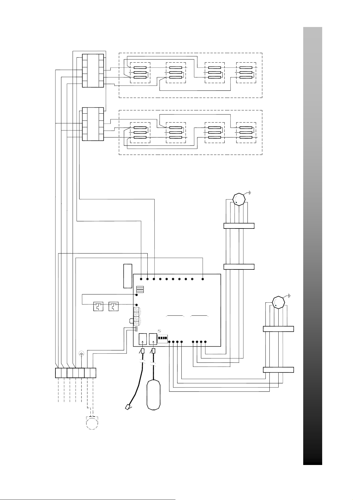
APPENDIX 2C — WIRING DIAGRAM HX2000ER
400V / 3ph / 50Hz
Sensor
External Air
9901098-2-1 Page | 22
Page 23
White
Blue
L
N
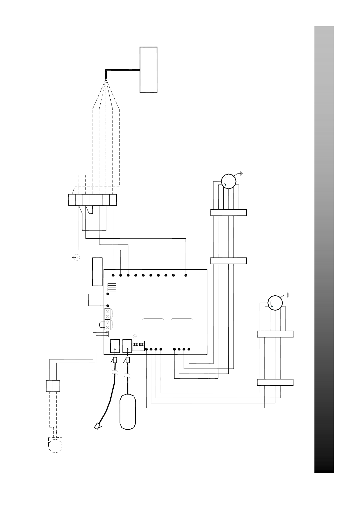
230V / 1ph / 50Hz
4
L
EE
N
BLOCK
TERMINAL
3 Port Valve
Orange
Grey
Green/Yellow
1~
1
2
3
Brown
Fan Motor 1
Orange
Violet
Brown (High)
Blue (Neutral)
0
Red (Low)
Grey
2
345
1
Green/Yellow
White
Black
Brown
K1
K3
K4
K6
F1 = 6.3A (T)
F2 = 125mA (F)
F1 F2
Live 1 K2
J2
K7
Live 2 K5
Blue
K9
Live 3 K8
Neutral K10
White
Blue
Red
Black
1~
HEALTHY
INHIBIT
LED 1
J3
e
l
b
6
5
To Slave
a
C
e
v
a
l
S
/
r
e
t
s
a
M
Air Curtain
ON
1234
REMOTE
CONTROL
Black
2
Fan
Motor
Low speed
High speed
Medium speed
Neutral
White
Blue
Red
Black
1
Fan
Motor
Low speed
High speed
Medium speed
Neutral
ECOPOWER CONTROLLER - CVR 1008
White
Blue
Red
Fan Motor 2
Orange
Violet
Brown (High)
Blue (Neutral)
0
1
White
Black
Grey
234
Red (Low)
5
Blue
Red
Sensor
External Air
9901098-2-1 Page | 23
APPENDIX 2D — WIRING DIAGRAM HX1000WR, HX1500WR and HX2000WR
Page 24
1~
Fan Motor 1
Orange
Violet
Blue (Neutral)
0
Brown (High)
1
Grey
2
Red (Low)
345
TERMINAL
White
Brown
K1
K3
K4
K6
F1 = 6.3A (T)
F2 = 125mA (F)
F1 F2
Live 1 K2
J2
HEALTHY
INHIBIT
LED 1
Brown
Blue
Green/Yellow
LL
E
N
BLOCK
E
N
To Slave
Air Curtain
J3
e
l
b
Ca
e
v
a
l
S
/
r
e
t
s
a
M
ON
1234
REMOTE
CONTROL
K7
Live 2 K5
Fan
High speed
Black
Blue
Live 3 K8
2
Motor
Medium speed
Low speed
Neutral
White
Red
Blue
K9
Neutral K10
1
Fan
Motor
Medium speed
Low speed
Neutral
High speed
White
Black
Blue
Red
ECOPOWER CONTROLLER - CVR 1008
Fan Motor 2
Black
Blue
Brown (High)
Blue (Neutral)
0
1
Red
Grey
234
1~
Orange
Violet
Red (Low)
5
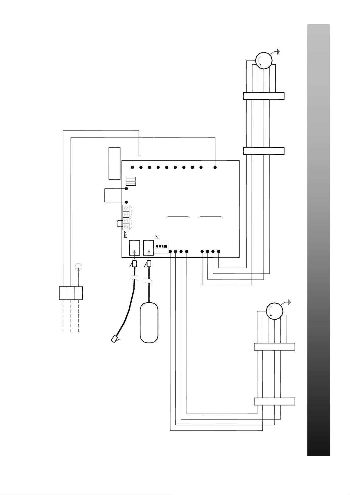
230V / 1ph / 50Hz
White
Blue
Black
Red
9901098-2-1 Page | 24
APPENDIX 2E — WIRING DIAGRAM HX1000AR, HX1500AR and HX2000AR
Page 25
20. DECLARATION OF CONFORMITY
Thermoscreens Ltd
St. Mary’s Road
Nuneaton
Warwickshire
CV11 5AU
ed Kingdom
Unit
Telephone: +44 (0)24 7638 4646
Fax: +44 (0)24 7638 8578
EC DECLARATION OF CONFORMITY
as defined by the EC Council Directive on Machinery 2006/42/EC, the Low Voltage Directive 2006/95/EC,
Electromagnetic Compatibility Directive 2004/108/EC, the Pressure Equipment Directive 97/23/EC,
the Energy related Products Directive 2009/125/EC
Herewith we declare that the air movement equipment designated below, on the basis of its design and
construction in the form brought onto the market by us in accordance with the relevant safety, health and
performance requirements of the Machi nery.
If alterations are made to the machinery without prior consultations with us, this declaration becomes invalid.
Designation of Equipment: AIR CURTAINS
Series Type: HX1000A; HX1000E; HX1000W; HX1500A; HX1500E; HX1500W;
HX2000A; HX2000E; HX2000W
(in Casing Styles: Surface Mount, Recessed, Conce aled)
Relevant EC Council the Machinery Directive (2006/42/EC)
Directives: the Low Voltage Directive (2006/95/EC)
the Electromagnetic Compatibility Directive (2004/108/EC)
the Energy related Products Directive (2009/125/EC)
Applied Harmonised Machinery - EN ISO 14121-1:2007, EN 294:1992, EN 414:2000
Standards: LVD - EN 60335-1:2002, +A14 incorporating A1, A2, A1 1,
A12 & A13, EN 60335-2-30:2009, EN 60335-2-40:2 003,
EMC - EN 61000-6-1:2007, EN 61000-6-3:2007,
EN 61000-3-2:2006 + A2:2009, EN 61000-3-3:2008
ErP - ISO 5801:2007, ISO 12759:2010
Basis of Self Attestation: Quality Assurance to BS EN ISO 9001: 2008
B.S.I. Registered Firm Certificate Number FM 85224
SGS Test Report ELS150049/2/R/DC/11; GL Test Report TR/09/149;
SGS Test Report DUR43601/1/EMC/ST/05
Responsible Person: Mr. P.Casey, Site Managing Director, Thermoscreens Ltd.
Date:
Signed:
9901098-2-1 Page | 25
1st January 2013
 Loading...