

Page 1
Controls.
EcoPower
INSTALLATION, OPERATION AND
MAINTENANCE INSTRUCTIONS
English
T9901125-1-1 UK Page | 1
Page 2

1 CONTENTS
1
CONTENTS ................................................................................................................................... 2
Page
2. DELIVERY CONTENTS ................................................................................................................ 3
3. REMOTE CONTROL INSTALLATION .......................................................................................... 4
4. REMOTE CONTROL OPERATION ............................................................................................... 5
Thermoscreens Ltd
St. Mary’s Road
Nuneaton
Warwickshire
England
CV11 5AU
Email: sales@thermoscreens.com — http://www.thermoscreens.com
Tel: +44 (0) 24 7638 4646 — Fax: +44 (0) 24 7638 8578
T9901125-1-1 UK Page | 2
Page 3

2. DELIVERY CONTENTS
Depending on the optional controllers and air curtain model selected one of the following controlle rs is
supplied.
NOTE: If any parts are missing or damaged contact your place of purchase.
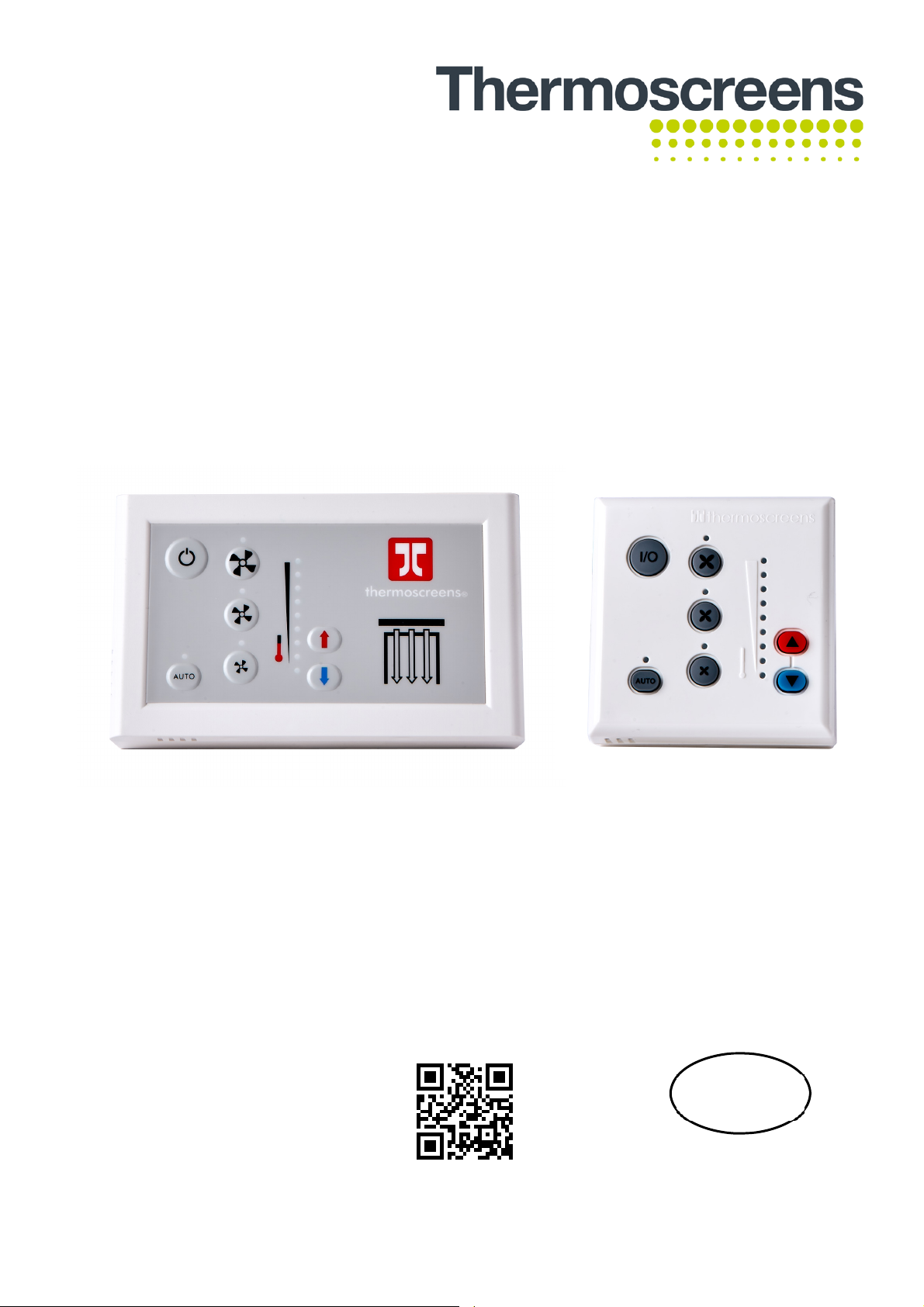
Ecopower Remote Control
(for Electric and Water Heated units)
OR
Supplied with 6m RJ Control Cable
Remote Control Switch
(for Ambient units)
Ecopower Plus Remote Control
(for Electric and Water Heated units)
T9901125-1-1 UK Page | 3
Page 4

3. REMOTE CONTROL INSTALLATION
Mount the Ecopower or Ecopower Plus Remote Control in a convenient position directly to the wall or
onto a switch box. As the Remote Control has a room air temperature sensor in it, which may be
selected, avoid a location where the Remote Control would see false room temperatures such as in
direct sunlight or on a very cold wall. Seal any openings going into the wall at the rear of the control to
avoid cold draughts blowing into the control and giving false temperatures.
3.1 Ecopower Controller Wall Mounting
Step 1 Using a screwdriver undo the screw on the top of the Remote Control case and pull the back
case away (see Fig 1 and Fig 2 below).
Step 2 Feed one end of the RJ control cable through the back case,
secure it, then screw the back case to the wall using suitable
fixings (not supplied) (see Fig 3).
Step 3 Connect the RJ plug to the RJ socket on the PCB in the
Remote Control.
Step 4 Refit the front case.
Fig 1
Fig 2
Fig 3
3.2 Ecopower Plus Controller Wall Mounting
Step 1 Place a slotted screwdriver to each slot on the bottom edge of
controller (see Fig 4). Push and twist to release the top half of
the controller.
Note: dimensions of controller are 148 x 90 x 33mm (l x h x d).
Step 2 Feed one end of the RJ control cable through the back case,
secure it ensuring the back case slots are towards the bottom
and then screw the back case to the wall using suitable fixings
(not supplied).
Step 3 Connect the RJ plug to the RJ socket on the PCB in the
Remote Control.
Step 4 Refit the front case.
T9901125-1-1 UK Page | 4
Fig 4
Fig 5
Page 5

3.3 Remote Control Settings
On the back of the PCB inside the Ecopower/Ecopower Plus
Remote Control you will find four DIP switches (see Fig 6) that
provide optional features detailed in Table 1 below.
DIP Feature Explanation Default Notes
1 Reset on power-up On restoring power after an
electrical interruption all Remote
Control settings are retained
2 Stop fan on cold Fans are switched off when
heating level is achieved (AUTO
mode only)
3 Never blow cold Air curtain always heats in
AUTO mode
4 Room air
temperature control
Enables the room air sensor in
the Remote Control
Fig 6
ON WARNING! – Fans start
on their own after power
is restored
OFF
OFF Will not go to ambient
mode
OFF Disables all o t her
temperature sensors
Table 1
4. REMOTE CONTROL OPERATION
4.1 Remote Control Switch (for Ambient units)
1 On/Off
Turns the air curtain fans On or Off.
2, 3 & 4 Fan speed
Switch fan speed between Low, Medium and High respectively.
3
4
2
1
T9901125-1-1 UK Page | 5
Page 6

4.2 Ecopower/Ecopower Plus Remote Control (for Electric and
Water Heated units)
Heating level scale
Use the Remo
te Control to operate the air curtain as follows:
1 On/Off
Turns the air curtain On or Off.
NOTE: If an electric heated air curtain is heating when switched off the fan will run-on for
approximately 2 minutes to dissipate excess heat.
2 Manual/Automatic
Switches between Manual and Automatic modes.
The Auto On indicator LED is lit for "Auto Mode" and unlit for "Manual Mode".
3 & 4 Heating level controls
Manual mode
Select heating level from zero, to half heat, to full heat by stepping up or down with the heating level
controls. The heating level scale shows the level selected.
Automatic mode
Heat output is controlled automatically according to:
Inlet air temperatur
Room air temperature
e, or
This is dependent on the settings made in Section 3.3 Remote Control Settings (DIP switch 4).
5, 6 & 7 Fan speed
Switch fan speed between Low, Medium and High respectively. The appropriate LED illuminates.
NOTE: for small lobby areas, operate
T9901125-1-1 UK Page | 6
air curtain in automatic mode (recommended).
 Loading...