

Thermoscreens C1000R, C1500R, C2000R, C1000AR, C1500AR Installation, Operation & Maintenance Instructions Manual
...Page 1
C-RECESSED RANGE AIR CURTAINS
INSTALLATION, OPERATION & MAINTENANCE INSTRUCTIONS
PLEASE READ THESE INSTRUCTIONS CAREFULLY BEFORE ATTEMPTING INSTALLATION
4001150-6 Page 1 of 128
Page 2
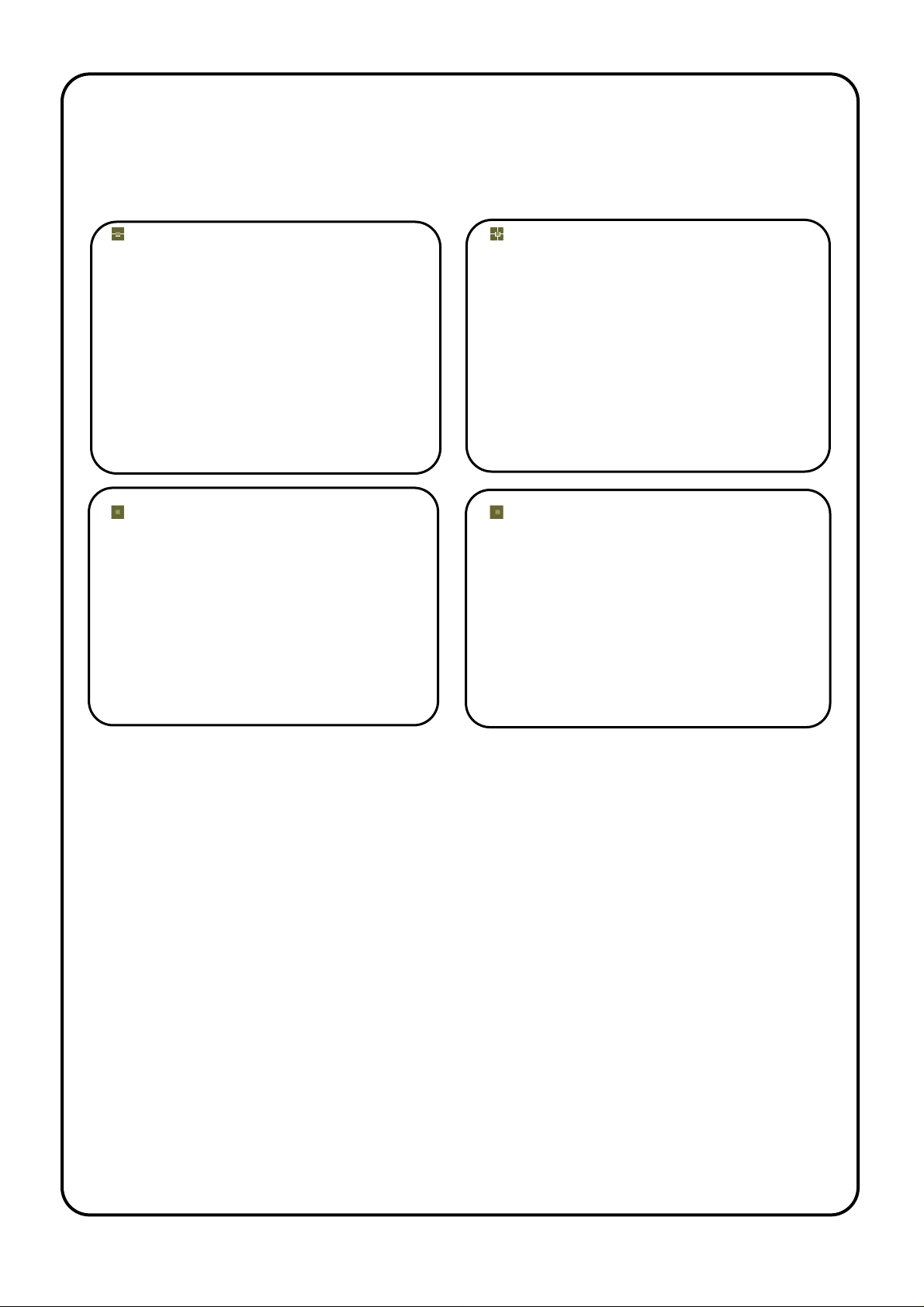
UN-PACKING YOUR C-RECESSED AIR CURTAIN
The following items are supplied and packaged within the boxes.
C-Recessed Air Curtain
Motorised Valve
(Ecopower LPHW units only)
Remote Control
Ecopower
Electric & LPHW
Manual Ambient
Recessed Grille
If anything is missing or damaged please contact your place of purchase immediately.
For your records
Date of Purchase……………………………..
Place of Purchase…………………………….
Serial Number…………………………………
For warranty purposes proof of purchase is necessary so please
keep a copy of your invoice.
(All documentation supplied with each unit should be stored and kept for future reference).
4001150-6 Page 2 of 128
Page 3
INSTALLATION OF YOUR HORIZONTAL APPLICATION C-RECESSED AIR CURTAIN
The C-Recessed air curtain has been designed for recessing within ceiling voids
or bulkheads.
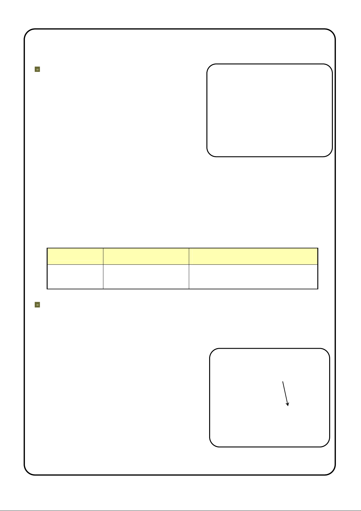
Location
Ensure that the unit is mounted within its height
specification of 1.8m to 2.75m maximum (from floor
level to the underside of the unit/grille) and that it is
situated as close to the door as possible.
Note: The air discharge should be nearest to the
door as shown in adjacent figure. Ensure the air
curtain is as close to the door opening as possible
for best performance, obstructions such as door
opening devices, structural beams etc will reduce
the performance.
Note the C-Recessed air curtain has a series of punched air vent ilation slots along one side
panel of the unit which will be within the ceiling void once the unit is installed. There m ust be
an air gap of 50mm minimum between these ventilation holes and any obstruction/bulkhe ad
within the ceiling void to allow ventilation air to easily enter the air curtain via these slots.
Furthermore, the ceiling void must be sufficiently large and freely ventilated so there will be
an adequate supply of ventilation air (m
3
/hr) to the unit, see Table 1. If the ceiling void is
enclosed around the air curtain it will need an air ventilation grille of effective free area (cm
as given in Table 1 and an adequate air path within the void for air to enter the punched air
ventilation slots.
Table 1
Air curtain
Required air flow within
ceiling void (m3/hr)
Effective free area of ventilation grille
for an enclosed ceiling void (cm2)
C1000R 353 500
C1500R 421 700
C2000R 707 1200
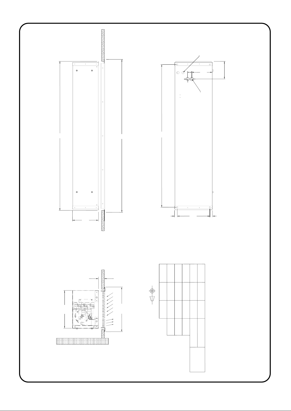
Ceiling Suspension
Make the cut-out in the ceiling to the dimensions given in Figure 1, ensuring the length of the
hole is exact. The air curtain will fit through the ceiling cut-out, ensure there is sufficient
height clearance in the ceiling void to do this. Alternatively, the ceiling can be fitted after the
air curtain has been installed.
Clearance holes for M8 threaded rod to enter from
above are provided on the top face of the casing (4x,
for dimensions see Figure 1) allowing the unit to be
suspended. Insert rod through each hole in top and
fixing
bracket
attach onto each fixing bracket at lower edge of air
curtain (see insert). Lock rod in place using M8 nut
above and below fixing bracket (threaded rod and
locking nuts are not provided). Ensure rod does not
come below bottom face of unit.
Ensure each of the threaded rods are secured on to
a suitable structure that can support the weight of
the unit (for unit weights see Table 2)*.
* It is the sole responsibility of the installer to ensure that the building fixing points and
suspension system used are suitable for the air curtain being installed
2
)
4001150-6 Page 3 of 128
Page 4
Electrical
supply inlet
33
165
1m-140
2m-150
1.5m-140
B
206
CEILING LEVEL
C
25-85mm
A
C2000R
2040
22
2090
LPHW connections
Rp 1/2 (1/2" BSP female)
257
22
301
Figure 1
1579
1529
C1500RC1000R
353
1179B(mm)
1129
A(mm)
15791179 2090
1209 1609 2120
C(mm)
Length(mm)
Cut-Out
311 311 311
Width(mm)
in Ceiling
4001150-6 Page 4 of 128
Page 5

Safety and Electrical Connections
All electrical wiring and connections MUST be carried out by a competent qualified
electrician in accordance with the latest edition of the IEE wiring regulations and/or
local statutory regulations.
A single phase or 3 phase isolator with a contact separation of at least 3mm in all poles
must be fitted to the supply wiring (the isolator must be fitted in an accessible position).
The air curtain must be earthed.
The appliance must be connected using cables having an appropriate temperature
rating (heat resistant).
Ensure that the supply cables, circuit breakers and other electrical installation
equipment are correctly sized for the air curtain being installed; see Table 2.
On a 3 phase electrical supply the unit requires a neutral connection (3N~).
Cable glands used for the Electrical Input must be rated IP21 or higher.
Table 2
Air Curtain Electrical
Supply
Rated Power
Input (kW)
Current per
phase (A)
Heat Output
(kW)
Weight
(kg)
(V/ph/Hz)
C1000AR 230/1/50 0.15 0.7 N/A 19
C1500AR 230/1/50 0.20 0.9 N/A 25
C2000AR 230/1/50 0.25 1.1 N/A 35
C1000WR 230/1/50 0.15 0.7 6.0 20
C1500WR 230/1/50 0.20 0.9 9.0 27
C2000WR 230/1/50 0.25 1.1 12.0 37
C1000ER 400/3/50 9.15 13.7 4.5/9.0 22
C1500ER 400/3/50 12.20 18.3 6.0/12.0 30
C2000ER 400/3/50 18.25 27.2 9.0/18.0 41
Fitting/Connecting the Ecopower Remote Control (excluding Ambient)
The remote control unit should be located in
a suitable place for easy access, it can be
fixed to the wall via two key-hole slots. Drill
3.5mm
and fix the screws into the wall leaving a
small gap between the head and the wall,
lower the unit onto the screws, for fixing
80mm
6mm
centres see adjacent figure. Ensure
suitable fixing screws are used.
The remote control is supplied with 3m of cable and a pre-fitted RJ connecting plug.
Ensure the remote control cable is safely secured and connected.
4001150-6 Page 5 of 128
Page 6

Fitting of the Recessed Grille
The grille consists of a frame, grille core (fitted
within the frame) and four brackets (note: the
brackets are fixed to the frame).
Removal of Grille Core
Prior to fitting the grille to the air curtain and the
ceiling the grille core will need to be removed from
its frame. Release the grille core by unfastening
the two conical bolts fitted at each end of the grille
core. Push against the spring loaded pins and the
grille core can now be pulled clear of its frame.
Note: the grille core will still be attached to the
frame via cord safety ties.
The rectangular hole in the ceiling must be
sized to suit the grille frame, see Figure 1
for dimensions.
Attaching the Grille to the Air Curtain
Before lifting the grille frame into position locate the four M6 bolts (two inside each end
of the air curtain). Remove the M6 bolts and lift the frame into position (ensure that
when fitted the air discharge vanes align with the air discharge of the air curtain, see
Figure 1), screw each M6 bolt through the slot in the grille bracket until all four are
located into place. Adjust the height of the grille frame (via slots in brackets) so the
frame fits nicely against the under side of the ceiling. Once the desired height is
achieved tighten each M6 bolt in place locking the grille frame into the correct position.
Adjusting the Separator Plate
Within the air curtain there is a sliding separator plate,
this needs adjusting up or down to stop the air
discharge re-circulating within the air curtain. To adjust
the separator plate release the M6 bolts at either end,
extend the slide plate so that it will just touch the
topside of the grille along its whole length and tighten
the bolts. It will be necessary to fit the grille core to
gauge where the separator plate should be fitted.
Fitting the Grille Core
Once the above is complete the grille core can be refitted, to do so locate each spring
loaded pin in its locating hole, push against the spring loaded pins to allow the fixed
pins to locate within their fixing holes. Tighten and secure the conical bolts fitted at
each end of the grille core.
Once the ceiling is finished remove the protective plastic film from the recessed grille
frame.
4001150-6 Page 6 of 128
Page 7

LPHW Models
For LPHW models ensure suitable water mains isolation valves are fitted in the flow
and return pipework.
When fitting the 3-port valve ensure that the pipe connections are fitted as detailed
below and are in accordance with the manufacturers leaflet supplied with the valve.
Air Curtain Water Flow Rate (l/s)
Coil Water Pressure Drop (kPa)
82/72 °C
C1000WR 0.14 2.77
C1500WR 0.21 6.74
C2000WR 0.29 13.40
Ambient Models
Ambient units are supplied with a remote switch
unit. The switch unit allows the air curtain to be
powered ON/OFF and select one of three fan
speeds.
Multiple Installation (Ecopower only)
To Master/Slave two or more air curtains together the remote control is plugged into
the Master unit and a RJ lead should be connected from the Master to the Slave
unit(s). Thermoscreens 3m RJ extension leads are available and must be ordered
separately. Additional air curtains, up to a maximum of eight units, may be connected
as indicated below. For Master/Slave configuration an independent mains supply as
per Table 2 must be supplied to each air curtain.
4001150-6 Page 7 of 128
Page 8

Ecopower Controller Motherboard (v8)
Function
Fan Heat Interlock –
The heat output is dependent on the fan
speed. If low or medium fan speed is
selected the heat output can only go up to
first heat stage. Only if the unit is operating
on high fan speed can the second heat
stage be selected. This feature operates in
manual or auto mode.
Disable Fan Run-on –
Disable fan run-on.
Thermostat Master –
Only the air sensor thermistor in the master
air curtain will be used for measuring the
reference air temperature for the whole
master/slave installation.
Overheat Fan Disable –
If DIP4 is on and thermal overheat trips,
heat and fan circuits are isolated and LED’s
on wall switch flash. If DIP4 is off and TOC
trips out, only the heat circuit is isolated and
the LED’s on the wall switch flash.
Retain User Settings (toggle) –
If electrical supply to the air curtain is
removed, upon restoring electrical supply
the customer’s settings on the remote
control will be retained, i.e. if unit were
operating beforehand, it would
automatically start up again and operate on
the exact same settings as before.
Fan run-on time set two minutes. Built-in If “FAN ONLY” has been selected, at
Reduce time for fan speeds to turn on and
index up through Low, Medium and High
fan speed when turning on via the
BMS/Remote On/Off option.
- white rectangle indicates the moveable head of e ach 4 way DIP switch
Control
DIP1 Option
ON
OFF
1 2 3 4
DIP2 Option
(LPHW &
Ambient only)
ON
OFF
1 2 3 4
DIP3 Option
ON
OFF
1 2 3 4
Suitable on vertical electrically heated
Designer air curtain. Maximum heat
output achieved if maximum fan speed
selected. Independently set-up DIP
switch on each mother board.
Must only be used for LPHW and
Ambient air curtains. Independently setup DIP switch on each mother board.
The air sensor thermistors in all the slave
air curtains will be ignored. This will then
avoid situations on larger doorways with
master/slave air curtains where some
units can blow cold air whilst others can
blow warm air, because they currently all
refer to their own air sensor for control of
the heat output of each air curtain.
The master air curtain need not be the
one that the wall control is plugged into.
DIP4 Option
(Electric only)
ON
OFF
1 2 3 4
Wall switch upgrade required.
The handset has to be powered on.
Independently set-up DIP switch on each
mother board.
To remove fault, isolate electrical supply
to air curtain, reset TOC and reconnect
supply.
Optional
feature –via
secret key
press (Fandown)
Wall switch upgrade required.
To toggle – switch unit on from handset.
Hold Auto button till Auto LED flashes.
Press fan down button to toggle
selection.
switch off, no fan run-on.
Built-in
Comments
Standard
As supplied, the
default setting would
be for heat and fan
settings to be
independent (DIP1
OFF).
As supplied, the
default setting would
enable fan run-on
(DIP2 OFF).
As supplied, the
default setting would
be for the air sensor
thermistor on all units
to be measuring
(DIP3 OFF).
As supplied, the
default setting would
enable fan if TOC trips
(DIP4 OFF).
NB: If TOC operates
with an upgraded
switch the LED’s on
switch flash,
regardless of DIP4
settings.
As supplied, the
default setting would
be for the unit to start
up again automatically.
Need to do the secret
key presses to revert
back to “nothing
happens” when power
is restored, as we have
it now.
4001150-6 Page 8 of 128
Page 9

DIP switches fitted on the Ecopower board provi de a selection of optional features as described above. Isolate and
switch electrical power off before configuring and/or changing any DIP switch settings.
• Easy plug-in arrangement for remote air sensor thermistor on a 1m lead. Plugging-in the remote air sensor to J3
disables the standard air sensor thermistor alr ea dy fitte d on the Ecopower board. As supplied, the board will not have
the remote air sensor fitted.
• An INHIBIT two screw terminal fitted on the Ecopower board for BMS remote On/Off feature.
If the terminal is linked, i.e. by 2 wires to a remote volt free contact, the unit will run. If it is open c ircuit across the
terminal the unit will switch off. This remote On/Off feature has global switching logic, i.e. if you master/slave several
units together you need connect the remote contact to only one of them to turn all units on and off in the master/slave
system. As supplied, a wire link will be fitted to the terminal block on every unit. For summer settings place a 3.3kΩ
resistance across the INHIBIT terminal, with these settings fans only will run ev en if controller is requesting for heat.
Customer Building Management System
ECOPOWER BOARD
• A HEALTHY two screw terminal is included on the board for a fault signal indicatio n if the electric elements overheat
cut-out has operated. A healthy system provides a 24V DC signal at the terminals compared to an overheat fault which
provides OV DC.
4001150-6 Page 9 of 128
Page 10

4001150-6 Page 10 of 128
Page 11

4001150-6 Page 11 of 128
Page 12

4001150-6 Page 12 of 128
Page 13

Ecopower Remote Control Operation
Auto Mode
Higher Fan Speed
Higher Heat
Auto on Indicator
Fan Speed Indicator
On / Off
Lower Heat
Lower Fan speed
Heating Level Indicator
Push On/Off switch to turn On, then operate as follows :-
Auto Switches between manual and automatic heat regulation.
The Auto on indicator LED is lit for "Auto Mode" and un-lit
for "Manual Mode".
On/Off Turns the air curtain On or Off (when turned off the settings for
heat and fan speed are retained). If the air curtain is heating
when it is turned off with this switch the fan will run-on for a time
(approx. 2 minute) to dissipate excess heat.
Selects the appropriate fan speed (Low, Medium or High) to suit the
air curtain height and outside wind conditions. Fan speed can be
changed when unit is in either Auto or Manual Modes. A fan speed
indicator LED shows which fan speed is selected.
In "Auto Mode” the air curtain measures the incoming air temperature
and automatically selects the necessary amount of heat to keep it at
the level selected. Heating level indicator LED's go from 0% to 100%
in 8 steps to show the level selected.
In "Manual Mode” heat output can be selected as Zero, Half Heat or Full
Heat. Heating level indicator LED's go 0%, 50% or 100% to show the
level selected.
Push On/Off switch again to turn Off
Note If the mains supply is isolated or cuts-out during operation the On/Off switch will need
to be pushed again to start the air curtain when the mains supply is restored. The
safety thermal cut-out in the air curtain may operate, if this happens it will need to be
reset by a competent technician.
4001150-6 Page 13 of 128
Page 14

Commissioning
Once the air curtain is functioning check that the fans operate at Low, Medium and High
speeds, that there is no excessive mechanical noise coming from the fans and that all fans
are working. If the unit is electric heated or water heated check that the air stream from the
discharge grille warms up across the whole length of the air curtain when heating is
selected. Check that heating increases as higher heat is selected and feel to see that the
warm air stream is reaching across the doorway with door open or closed. If an Ecopower
controller is being used check its operation in Manual Mode. Then select Auto Mode and
increase the heating set point until the air stream warms up. Reduce the heating set point
until the air stream goes cold.
Before leaving site it is important that the air curtain installation is “Handed-Over” to the
end user or his representative and the operation of it is fully explained and that they
understand how it operates. Explain also the service intervals and that the unit must be
regularly cleaned.
Fault Conditions
In the event of a fault with electrical heated air curtains the thermal cut out(s) may
operate. Note: If the mains supply is isolated during operation then the thermal cut
outs may operate.. The thermal cut out(s) are located within the unit directly above the
electric element banks (one on the 1 & 1.5m and two on the 2m model). There are two
fuses on the Ecopower circuit board which may blow in the event of a fault. For
Ambient units the fuse is located within the control panel at the left hand side of the air
curtain.
In the case of a fault condition (refer to flowchart) do not attempt to reset the thermal
cut outs or replace the fuses, arrange for a Thermoscreens appointed technician or
certified electrician to attend the unit to investigate the reason why the thermal cut
outs/fuse(s) have operated. Once the cause has been determined and rectified, they
will reset/replace the thermal cut out/fuse and function test the unit.
PCB Status
Fitted on the PCB board inside of the air curtain is an LED shown as LED1 on wiring
diagrams that will indicate the Ecopower control status.
1. LED flashing green – operation normal.
2. LED flashing red – low supply voltage.
3. LED permanently red – thermal cut outs open circuit (electrically heated models
only).
Note to reset the thermal cut outs please refer to Fault Conditions section detailed
above.
4001150-6 Page 14 of 128
Page 15

User Fault Finding Flowchart (for Ecopower Control)
Service Agent to
reset thermal cut-
out(s)
Service Agent to
investigate why
thermal cut-out(s)
have operated
Is Electrical
Power
switched on
Yes
Are the fans
operating
correctly
Yes
Select heat output
No
No
Do the LED’s
light up on
the remote
control
Yes
Switch on Electrical
Power
Connect remote control
and push On/Off switch
to turn unit on
No
No
Is the remote
control
plugged in
and turned
on
Yes
Yes
Check if thermal
cut-out(s) have
tripped (Electric
Heated only)
No
Contact Installer
No
Contact Installer
Is the unit
discharging
warm air
Yes
Unit is working
satisfactorily
4001150-6 Page 15 of 128
Page 16

Service & Maintenance
Always disconnect and isolate the mains electricity supply before installing,
maintaining or repairing this equipment. Note: All maintenance/repairs should
only be carried out by a competent electrician or Thermoscreens appointed
technician.
To ensure the air curtain operates at full efficiency the inlet/outlet grilles, fan impellers,
housings and motors must be kept free of dust and debris. Build up of dust on the fan
impellers can cause vibration, noise and excessive wear on the motor bearings.
Frequency of cleaning will depend on the environment, but we would recommend that
the unit be cleaned a minimum of every 3 months (failure to adequately maintain the
unit and provide a suitable cleaning schedule will result in performance degradation
and reduce the life expectancy of the air-curtain).
Remove the grille from the air curtain. Vacuum and clean the build-up of dirt and
debris within the air-curtain (please note that the motor(s) are permanently lubricated
and require no additional lubrication).
Once the air curtain has been cleaned check all electrical connections within the unit
ensuring terminals are tight and that crimped connections have not become loose.
Re-install the recessed grille ensuring the straight louvers are directly under the air
discharge and the 45° louvers are directly under the air intake. Reconnect the
electrical supply and fully function test the air-curtain to ensure correct operation (See
Commissioning).
Warranty
If any problems are encountered, please contact your installer/supplier. Failing this
please contact the Thermoscreens warranty department. All units are covered by a
two year warranty period.
Care has been taken in compiling these instructions to ensure they are correct, although
Thermoscreens disclaims all liability for damage resulting from any inaccuracies and/or
deficiencies in this documentation. Thermoscreens retain the right to change the
specifications stated in these instructions.
4001150-6 Page 16 of 128
 Loading...