

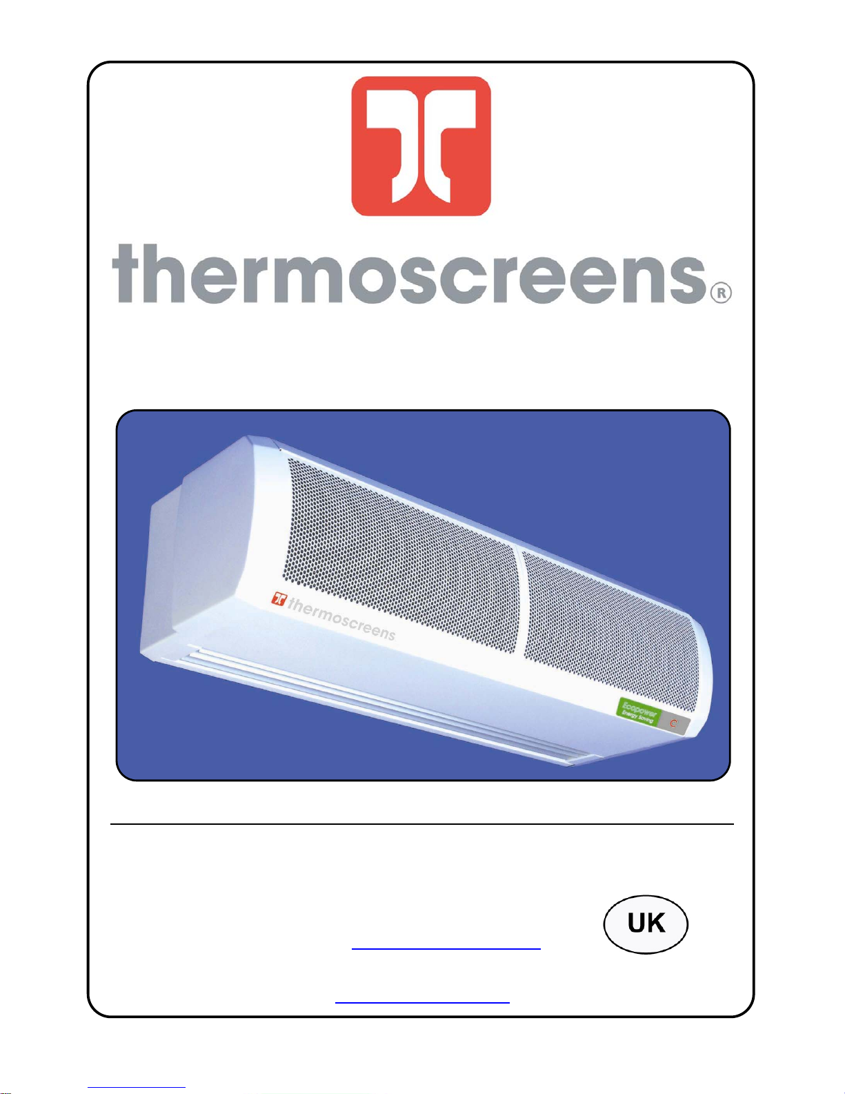
Thermoscreens C series, C1000A, C1500A, C2000W, C1500W Installation, Operation & Maintenance Instructions Manual
...Page 1
4001160-6 UK Page 1 of 16
C RANGE AIR CURTAINS
INSTALLATION, OPERATION & MAINTENANCE INSTRUCTIONS
PLEASE READ THESE INSTRUCTIONS CAREFULLY BEFORE ATTEMPTI NG INSTALLATION
Thermoscreens Ltd
St. Mary’s Road Nuneaton
Warwickshire England
CV11 5AU
Email: sales@thermoscreens.com
Tel: +44 (0) 24 7638 4646
Fax: +44 (0) 24 7638 8578
www.thermoscreens.com
Page 2
4001160-6 UK Page 2 of 16
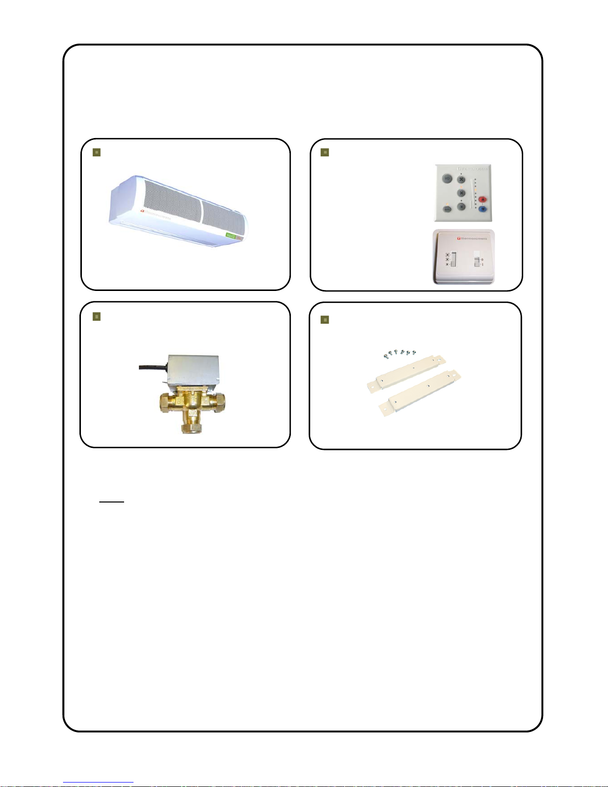
UN-PACKING YOUR C AIR-CURTAIN
The following items are supplied and packaged within the boxes.
C Air Curtain
Please note end caps are supplied loose
and can be fitted during installation
Motorised Valve
(Ecopower LPHW units only)
Remote Control
Ecopower
Electric & LPHW
Manual
Ambient
Wall Brackets & Fixing Bolts
(additional bracket and bolts supplied
for C1500/C2000 models)
Note Optional filters are available on Water and Ambient models only
and are packed separately.
If anything is missing or damaged please contact your place of purchase immediately.
For your records
Date of Purchase……………………………..
Place of Purchase…………………………….
Serial Number…………………………………
For warranty purposes proof of purchase is necessary so please
keep a copy of your invoice.
(All documentation supplied with each unit should be stored and kept for future reference).
Page 3
4001160-6 UK Page 3 of 16
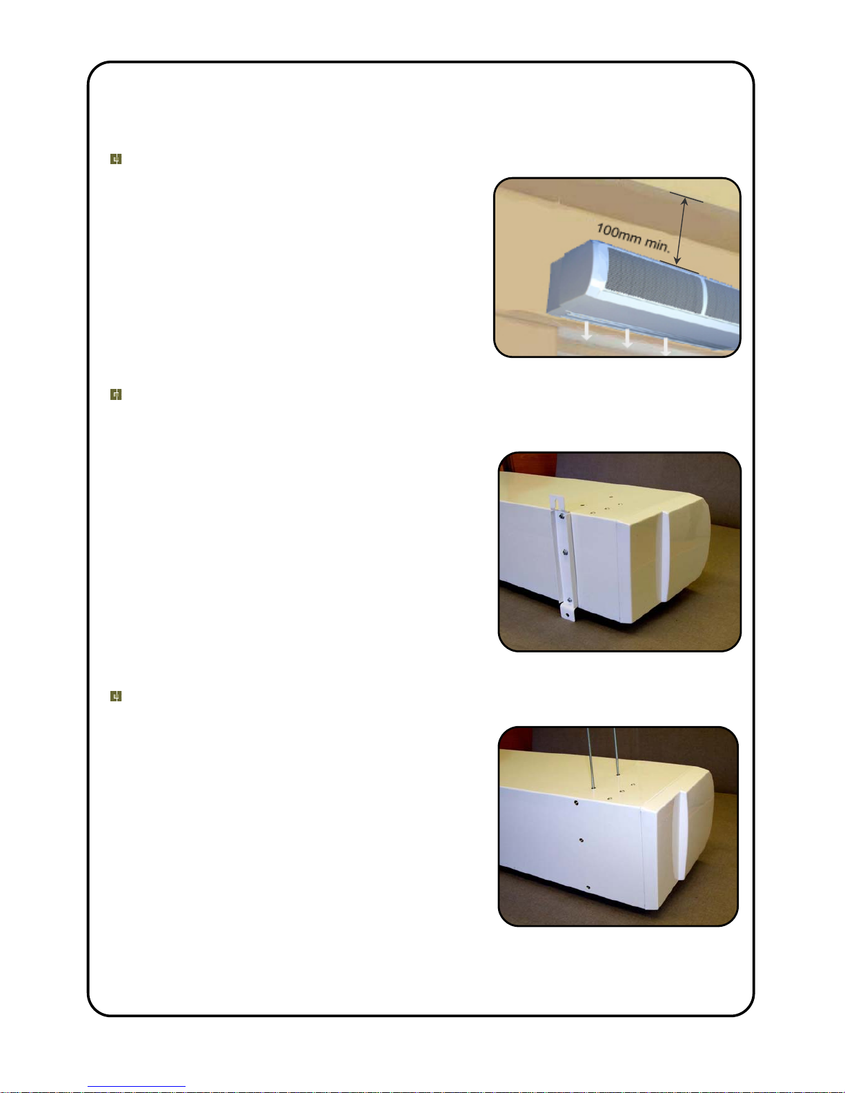
INSTALLATION OF YOUR HORIZONTAL APPLICATION C AIR-CURTAIN
The C air curtain has been designed for surface mounting only inside of
the building.
Location
Ensure that the unit is mounted within its height
specification of 1.8m minimum to 3.0m maximum
(from floor level to the underside of the unit) and
that it is situated as close to the door as possible
with a 100mm air gap above the air curtain (see
adjacent figure). In some cases it may not be
possible to mount the air curtain as close to the
door as possible as the air stream may strike the
top edge of the doorway, a structural beam or a
door opening device etc, therefore this will have
to be taken into account when locating the unit.
Wall Fixing
Bolt the wall brackets to the rear face of the unit
as shown in the adjacent figure (using the bolts
supplied). Before fitting the unit to the wall obtain
suitable fixing bolts, taking into account wall type
and unit weight (see table 1).
Step 1. Refer to Figure 1 for mounting details
and drill the wall accordingly.
Step 2. Screw in the top bolts leaving a small
gap between the head and the wall; lower the
unit onto the bolts via key hole slots in the top of
the wall brackets and then screw in the bottom
bolts.
Step 3. Ensure all fixing bolts are tightened to
stop the unit being lifted off the wall.
Ceiling Suspension
6mm threaded inserts are provided in the top
face of the casing (4 x M6 on the 1m and 6 x M6
on the 1.5/2m models, for dimensions see Figure
1) allowing the unit to be suspended on threaded
rod (threaded rod is not provided). Ensure each
of the threaded rods are secured on to a suitable
structure that can support the weight of the unit
(for unit weights see Table 1)*. When fitting the
threaded rod ensure that it does not interfere with
internal components. Fit locking nuts (not
supplied) and ensure they are engaged by a
minimum of 20mm to stop the threaded rod
rotating and coming away from the casing.
*Please note it is the sole responsibility of the installer to ensure that the fixing points
and bolts used are suitable for the air curtain being installed.
Page 4
4001160-6 UK Page 4 of 16
connection interface
Remote control
suitable for 25mm gland
Electrical supply inlets
C1500
C(mm) N/A
E(mm)
F(mm)
D(mm)
N/A
161
710
B(mm)
A(mm)
C1000
1137
908
275
Rp 1/2 (1/2in. BSP female)
LPHW connections
964704
161
874
1748
604
170
1208
21
120
1928
2200
C2000
1408
1669
M6 inserts
C
B
A
C
198
100
(min)
220
E
D
E
33
F
75
Figure 1
Page 5
4001160-6 UK Page 5 of 16
Safety and Electrical Connections
All electrical wiring and connections MUST be carried out by a competent qualified
electrician in accordance with the latest edition of the IEE wiring regulations and/or
local statutory regulations.
A single phase or 3 phase local isolator with a contact separation of at least 3mm in all
poles must be fitted to the supply wiring (the isolator must be fitted in an accessible
position).
The air curtain must be earthed.
The appliance must be connected by means of wires having an appropriate
temperature rating (heat resistant) (electric models only).
Ensure that the supply cables, circuit breakers and other electrical installation
equipment are correctly sized for the air curtain being installed; see Table 1 for Power
Ratings. See also data badge on the left hand side of unit under end cap.
On a 3 phase electrical supply the unit requires a neutral connection (3N~).
Cable glands used for the Electrical Input must be rated IP21 or higher.
Table 1
Air Curtain Electrical
Supply
(V/ph/Hz)
Rated Power
Input (kW)
Current per
phase (A)
Heat Output
(kW)
Weight
(kg)
C1000A 230/1/50 0.15 0.7 N/A 15
C1500A 230/1/50 0.20 0.9 N/A 21
C2000A 230/1/50 0.25 1.1 N/A 31
C1000W 230/1/50 0.15 0.7 6.0 18
C1500W 230/1/50 0.20 0.9 9.0 26
C2000W 230/1/50 0.25 1.1 12.0 37
C1000E 400/3/50 9.15 13.7 4.5/9.0 16
C1500E 400/3/50 12.20 18.3 6.0/12.0 23
C2000E 400/3/50 18.25 27.2 9.0/18.0 33
To gain access to the electrical
connections the air intake grilles must
be removed. Ensure electrical mains
supply to the unit is isolated. If end
caps are already fitted, remove them
from the air curtain first (see insert).
Two air inlet grilles are fitted on 1m,
three on 1.5m and four on 2.0m
models.
Remove intake grilles by unfastening
two screws on each grille; M4 x 10mm
Pozi No.2 screws accessed via larger
hole in the bottom of the grille (see
adjacent figure).
Optional filter fits inside
curve of inlet grille
Page 6

4001160-6 UK Page 6 of 16
Access can now be gained to make the
electrical connections.
Once connections have been
completed the inlet grilles should be
refitted and if fitted the end caps clipped
into place (see insert).
Please note the panels of the air curtain are coated in a protective film which should be
removed before use.
LPHW Models
For LPHW models ensure suitable water mains isolation valves are fitted in the flow and
return pipework. When fitting the 3-port valve ensure that the pipe connections are fitted
as detailed below and are in accordance with the manufacturers leaflet supplied with the
valve.
Air Curtain Water Flow Rate (l/s)
82/72°C
Coil Water Pressure Drop (kPa)
C1000W 0.14 2.77
C1500W 0.21 6.74
C2000W 0.29 13.40
Ambient Models
Ambient units are supplied with a remote switch unit.
The switch unit allows the air curtain to be powered
ON/OFF and select one of three fan speeds.
A
B
A/B
22mm pipe
22mm pipe
22mm pipe
15mm pipe
R
E
T
U
R
N
F
L
O
W
Page 7

4001160-6 UK Page 7 of 16
Fitting/Connecting the Remote Control
The Ecopower Plus controller uses extra low voltage to communicate via the RJ control
cable supplied. The controller should be located in a suitable place for easy access, it
can be fixed to the wall via various fixing slots
provided in the back case or onto an electrical
switch box (not provided). To mount controller
onto an existing switch box, feed one end of the
control cable through the switch box (see insert).
Using a screwdriver undo screw mounted on
the top of the controller case. Pull the front case
slightly forwards and lift the back case away.
Feed and secure the RJ control cable through
one of the openings in the back case and
secure back case to switch box using 2 x M3.5
mounting screws (not provided).
With the cable RJ plug locking clip lying nearest
to controller PCB, connect the RJ plug to the RJ
socket on the board.
Note: For controller DIP switch options refer to
Ecopower Plus Remote Control Operation and
DIP Switch Settings.
Refit the controller front case to the back case.
The air curtain end of the control cable should be
connected to one RJ socket fitted either on the
top panel for NT or the Ecopower motherboard
inside a recessed air curtain. Ensure the control
cable is safely secured.
Multiple Installation (Ecopower only)
To Master/Slave two or more air curtains together a suitable RJ lead should be
connected from the Master to the Slave unit. Thermoscreens 3.0m RJ extension leads
must be ordered separately. Additional air curtains, up to a maximum of eight units,
may be connected as indicated below. For Master/Slave configuration an independent
mains supply must be supplied to each air curtain.
Page 8

4001160-6 UK Page 8 of 16
Ecopower Controller Motherboard
Function
Control
Comments
Standard
Fan Heat Interlock –
The heat output is governed by the
fan speed. If low or medium fan
speed is selected the heat output
will operate on only first heat stage.
Second stage heating will only
operate on high fan speed.
DIP1 Option
Suitable on vertical electrically
heated Designer air curtain.
Maximum heat output achieved if
maximum fan speed selected.
Independently set-up DIP switch
on each mother board. This
feature operates in manual or
auto mode.
As supplied, the
default setting would
be for heat and fan
settings to be
independent (DIP1
OFF).
Disable Fan Run-on –
Disable fan run-on.
DIP2 Option
(LPHW &
Ambient only)
Must only be used for LPHW and
Ambient air curtains.
Independently set-up DIP switch
on each mother board.
As supplied, the
default setting would
enable fan run-on
(DIP2 OFF).
Thermostat Master –
Only the air sensor thermistor in
the master air curtain will be used
for measuring the reference air
temperature for the whole
master/slave installation.
DIP3 Option
The air sensor thermistors in all
the slave air curtains will be
ignored. This will then avoid
situations on larger doorways with
master/slave air curtains where
some units can blow cold air
whilst others can blow warm air,
because they currently all refer to
their own air sensor for control of
the heat output of each air
curtain.
The master air curtain need not
be the one that the wall control is
plugged into. This dip switch
setting must also be used for
Global Switching (Master/Slave)
via the INHIBIT terminal – see
next page.
As supplied, the
default setting would
be for the air sensor
thermistor on all
units to be
measuring
(DIP3 OFF).
Overheat Fan Disable –
If DIP4 is on and thermal cut-out(s)
operate both heat and fan circuits
are isolated and LED’s on wall
switch flash. If DIP4 is off and
thermal cut-out(s) operate, only the
heating circuit is isolated and the
LED’s on the wall switch flash.
DIP4 Option
(Electric only)
Independently set-up DIP switch
on each mother board.
To remove fault, isolate electrical
supply to air curtain, reset TOC
and reconnect supply.
As supplied, the
default setting would
enable fan if TOC
trips (DIP4 OFF).
Fan run-on time set two minutes.
Built-in
If “FAN ONLY” has been
selected, at switch off, no fan runon.
- white rectangle indicates the moveable head of each 4 way DIP switch
DIP switches fitted on the Ecopower board provide a selection of optional features as
described above. Isolate and switch electrical power off before configuring and/or
changing any DIP switch settings.
ON
OFF
1 2 3 4
ON
OFF
1 2 3 4
ON
OFF
1 2 3 4
ON
OFF
1 2 3 4
Page 9

4001160-6 UK Page 9 of 16
Easy plug-in arrangement for remote air sensor thermistor on a 1m lead. Plugging-in
the remote air sensor to J3 disables the standard air sensor thermistor already fitted
on the Ecopower board. As supplied, the board will not have the remote air sensor
fitted.
An INHIBIT two screw terminal fitted on the Ecopower board for BMS remote On/Off
feature. If the terminal is linked, i.e. by 2 wires to a remote volt free contact, the unit will
run. If it is open circuit across the terminal the unit will switch off. This remote On/Off
feature has global switching logic, i.e. if you master/slave several units together you
need connect the remote contact to only one of them to turn all units on and off in the
master/slave system. For global switching to work on the slave units, need to set DIP3
Option (see previous page) on the unit that the remote contact is wired to and have
previously turned the unit on with the wall switch. As supplied, a wire link will be fitted
to the terminal block on every unit. For summer settings place a 3.3kΩ resistance
across the INHIBIT terminal, with these settings fans only will run even if controller is
requesting for heat.
ECOPOWER BOARD
Customer Building Management System
A HEALTHY two screw terminal is included on the board for a fault signal indication if
the electric elements overheat cut-out has operated. A healthy system provides a 24V
DC signal at the terminals compared to an overheat fault which provides OV DC.
Page 10

4001160-6 UK Page 10 of 16
Page 11

4001160-6 UK Page 11 of 16
Page 12

4001160-6 UK Page 12 of 16
Page 13

4001160-6 UK Page 13 of 16
Ecopower Plus Remote Control Operation and DIP Switch Settings
On/Off (I/O)
Press On/Off switch (1) to turn the air curtain
On and operate as follows:-
Press Auto switch (2) to cycle between Manual
and Automatic modes. The Auto on indicator
LED is lit for "Auto Mode" and un-lit for "Manual
Mode".
Manual:
Heat output can be selected as Zero, Half Heat
or Full Heat. Heating levels are selected by
stepping up or down with switches (3) and (4).
Heating level indicator LED's go 0%, 50% or
100% to show the level selected.
Automatic:
If DIP switches 1, 2 and 4 on the Ecopower
motherboard are set to OFF, the air curtain
measures the incoming air temperature and
automatically selects the necessary amount of
heat to keep it at the level selected.
Fan Speed
Switches (5), (6) and (7) select fan speed low,
medium or high respectively. The appropriate
LED above each fan speed indicator is
illuminated to show which fan speed is selected.
Pressing the On/Off switch (1) again switches the
air curtain off with all the LED’s switched off. If a
heated air curtain is heating when switched off
the fan will run-on at low fan speed for an
extended time (approx. 2 minutes) to dissipate
excess heat.
DIP Switch Settings
At the back of the Ecopower Plus remote
control PCB there are four DIP switches (see
above) that provide the following optional
features.
DIP1 Restart on Power-Up – If electrical
supply to the air curtain is
interrupted, upon restoring electrical
supply, the customer’s settings on
the remote control will be retained.
The default is with this feature ON.
DIP2 Stop Fan on Cold – Fans switch off
when heating level is achieved
(Automatic mode only). The default
setting is with this feature OFF.
DIP3 Never Blow Cold – Unit always
heats in Automatic mode (i.e. will
not go to ambient mode). The
default setting is with this feature
OFF.
DIP4 Air Sensor in Controller – The air
sensor in the remote controller is
enabled (DIP4 ON) and the air
sensor on the Ecopower
motherboard in the air curtain is
disabled. Temperature control for
Automatic Mode is then done at the
remote control, which may be an
advantage to limit overheating of the
door entrance area. The default
setting is with this feature OFF.
Do not switch the air curtain On/Off from the isolator. If the mains supply is
isolated or cuts-out during operation the safety thermal cut-out(s) for electric
heated air curtains within the air curtain may operate. If this happens the
thermal cut-out(s) will need to be reset by a competent technician.
2
1
3
4
5
6
7
Heating Level
Scale
Page 14

4001160-6 UK Page 14 of 16
Commissioning
Set the discharge grille vanes so they point straight downwards over the doorway. Once
the air curtain is functioning check that the fans operate at Low, Medium and High
speeds, that there is no excessive mechanical noise coming from the fans and that all
fans are working. If the unit is electric or water heated check that the air stream from the
discharge grille warms up across the whole length of the air curtain when heating is
selected. Check that heating increases as higher heat is selected and feel to see that
the warm air stream is reaching across the doorway with door open or closed. If
necessary the vanes of the discharge grille can be angled either inwards or outwards if
this gives better penetration/warming of any incoming draughts. If an Ecopower
controller is being used check its operation in Manual Mode. Then select Auto Mode and
increase the heating set point until the air stream warms up. Reduce the heating set
point until the air stream goes cold.
Explain to the end user that the doorway should be closed whenever possible but that
during times of high pedestrian use it will become effectively ‘open doorway’. The air
curtain serves an essential purpose by saving energy and providing comfort to the
occupants when compared to an open doorway with no air curtain fitted.
Before leaving site it is important that the air curtain installation is “Handed-Over” to the
end user or his representative and the operation of it is fully explained and that they
understand how it operates. Explain also the service intervals and that the unit must be
regularly cleaned and if it has filters fitted that these require regular cleaning or
replacement.
Fault Conditions
In the event of a fault the thermal cut out(s) (Note: If the mains supply is isolated during
operation then the thermal cut outs may operate) or internal fuses may operate. The
thermal cut out(s) are located on the top face of the unit directly above the element
banks (one on the 1 & 1.5m and two on the 2m model). For Ecopower units two internal
electrical fuses are located on the Ecopower board; 6.3A (T) supplies the fan motors
within the air curtain and 125mA (F) controls the operation of the Ecopower board. For
Ambient and Standard LPHW units the fuse is located within the control panel at the left
hand end of the air curtain.
If for an electric heated air curtain an overheat fault occurs, or if J2 link is missing for
LPHW models, the LED’s on the remote control will flash and the Ecopower board status
LED on the board will be permanently red to indicate a fault.
In the case of a fault condition (refer to flowchart) do not attempt to reset the thermal cut
outs or replace the fuses, arrange for a Thermoscreens appointed technician or certified
electrician to attend the unit to investigate the reason why the thermal cut outs/fuse(s)
have operated. Once the cause has been determined and rectified, they will
reset/replace the thermal cut out/fuse and function test the unit.
PCB Status
Fitted on the PCB board inside of the air curtain is an LED shown as LED1 on wiring
diagrams that will indicate the Ecopower control status.
1. LED flashing green – operation normal.
2. LED flashing red – low supply voltage or controller not plugged into Ecopower
motherboard.
3. LED permanently red – thermal cut outs open circuit (electrically heated models) or
J2 link missing (LPHW models). Remote Control LED’s will also flash to indicate the
thermal cut-out(s) has operated or J2 link is missing.
Note to reset the thermal cut outs please refer to Fault Conditions section detailed above.
Page 15

4001160-6 UK Page 15 of 16
User Fault Finding Flowchart (for Ecopower Control)
Yes
Unit is working
satisfactorily
Switch on Electrical
Power
Connect remote control
and push On/Off switch
to turn unit on
Select heat output
Contact Installer
Service Agent to
investigate why
thermal cut-out(s)
have operated
Service Agent to
reset thermal cut-
out(s)
Contact Installer
Yes
No
Yes
Yes
No
No
No
Yes
Yes
No
No
Is Electrical
Power
switched on
Are the fans
operating
correctly
Is the unit
discharging
warm air
Check if thermal
cut-out(s) have
tripped (Electric
Heated only)
Do the LED’s
light up on
the remote
control
Is the remote
control
plugged in
and turned
on
Page 16

4001160-6 UK Page 16 of 16
Service & Maintenance
Always disconnect and isolate the mains electricity supply before installing,
maintaining or repairing this equipment. Note: All maintenance/repairs should
only be carried out by a competent electrician or Thermoscreens appointed
technician.
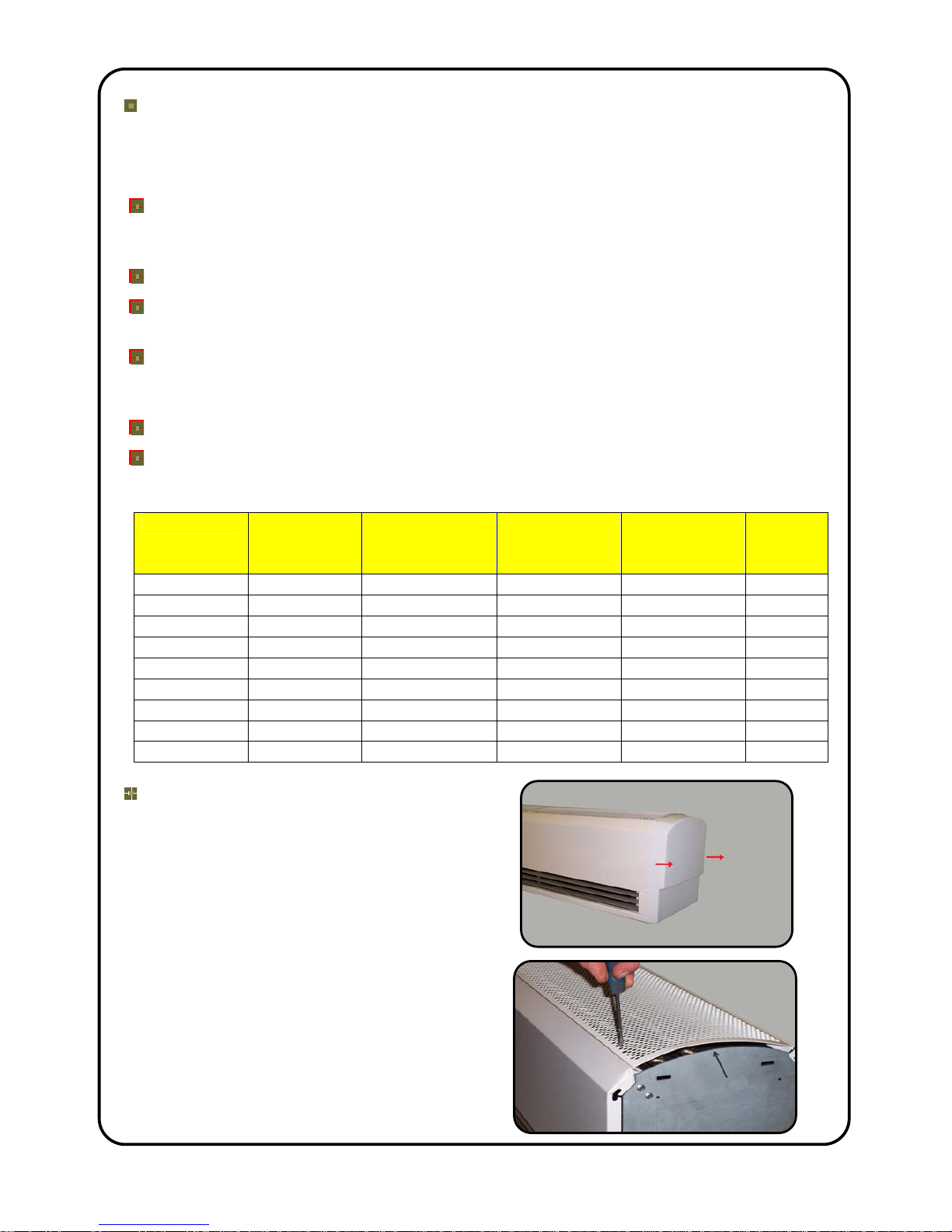
Once the mains supply is isolated, remove end caps from the air curtain (if fitted).
Remove each air intake grille by unfastening two screws on each grille - M4 x 10mm
Pozi No.2 screws accessed via the larger hole at the bottom of each grille.
To ensure the air curtain operates at full efficiency the inlet/outlet grilles, fan impellers,
housings and motors must be kept free of dust and debris. Build up of dust on the fan
impellers can cause vibration, noise and excessive wear on the motor bearings.
Frequency of cleaning will depend on the environment, but we would recommend that
the unit be cleaned a minimum of every 3 months (failure to adequately maintain the
unit and provide a suitable cleaning schedule will result in performance degradation
and reduce the life expectancy of the air-curtain).
Vacuum and clean the build-up of dirt and debris within the air-curtain (please note
that the motor(s) are permanently lubricated and require no additional lubrication).
If filters are fitted, ensure these are regularly inspected and cleaned or replaced. All
dirty or blocked filters should be immediately replaced.
Once the air curtain has been cleaned check all electrical connections within the unit
ensuring terminals are tight and that crimped connections have not become loose.
Refit inlet grilles and end caps. Reconnect the electrical supply and fully function test
the air-curtain to ensure correct operation (See Commissioning).
If the outer casing requires cleaning this should be done using a warm soft cloth.
Do not use solvents or abrasive materials.
Warranty
If any problems are encountered, please contact your installer/supplier. Failing this
please contact the Thermoscreens warranty department. All units are covered by a two
year warranty period.
Care has been taken in compiling these instructions to ensure they are correct, although
Thermoscreens disclaims all liability for damage resulting from any inaccuracies and/or
deficiencies in this documentation. Thermoscreens retain the right to change the
specifications stated in these instructions.
Thermoscreens Ltd
St. Mary’s Road Nuneaton
Warwickshire England
CV11 5AU
Email: sales@thermoscreens.com
Tel: + 44 (0) 24 7638 4646
Fax: + 44 (0) 24 7638 8578
www.thermoscreens.com
 Loading...