

Thermoscreens C1000R, C1500R, C2000R, C1000AR, C1500AR Installation, Operation & Maintenance Instructions Manual
...
C-RECESSED RANGE AIR CURTAINS
INSTALLATION, OPERATION & MAINTENANCE INSTRUCTIONS
PLEASE READ THESE INSTRUCTIONS CAREFULLY BEFORE ATTEMPTING INSTALLATION
4001150-6 Page 1 of 128
UN-PACKING YOUR C-RECESSED AIR CURTAIN
The following items are supplied and packaged within the boxes.
C-Recessed Air Curtain
Motorised Valve
(Ecopower LPHW units only)
Remote Control
Ecopower
Electric & LPHW
Manual Ambient
Recessed Grille
If anything is missing or damaged please contact your place of purchase immediately.
For your records
Date of Purchase……………………………..
Place of Purchase…………………………….
Serial Number…………………………………
For warranty purposes proof of purchase is necessary so please
keep a copy of your invoice.
(All documentation supplied with each unit should be stored and kept for future reference).
4001150-6 Page 2 of 128
INSTALLATION OF YOUR HORIZONTAL APPLICATION C-RECESSED AIR CURTAIN
The C-Recessed air curtain has been designed for recessing within ceiling voids
or bulkheads.
Location
Ensure that the unit is mounted within its height
specification of 1.8m to 2.75m maximum (from floor
level to the underside of the unit/grille) and that it is
situated as close to the door as possible.
Note: The air discharge should be nearest to the
door as shown in adjacent figure. Ensure the air
curtain is as close to the door opening as possible
for best performance, obstructions such as door
opening devices, structural beams etc will reduce
the performance.
Note the C-Recessed air curtain has a series of punched air vent ilation slots along one side
panel of the unit which will be within the ceiling void once the unit is installed. There m ust be
an air gap of 50mm minimum between these ventilation holes and any obstruction/bulkhe ad
within the ceiling void to allow ventilation air to easily enter the air curtain via these slots.
Furthermore, the ceiling void must be sufficiently large and freely ventilated so there will be
an adequate supply of ventilation air (m
3
/hr) to the unit, see Table 1. If the ceiling void is
enclosed around the air curtain it will need an air ventilation grille of effective free area (cm
as given in Table 1 and an adequate air path within the void for air to enter the punched air
ventilation slots.
Table 1
Air curtain
Required air flow within
ceiling void (m3/hr)
Effective free area of ventilation grille
for an enclosed ceiling void (cm2)
C1000R 353 500
C1500R 421 700
C2000R 707 1200
Ceiling Suspension
Make the cut-out in the ceiling to the dimensions given in Figure 1, ensuring the length of the
hole is exact. The air curtain will fit through the ceiling cut-out, ensure there is sufficient
height clearance in the ceiling void to do this. Alternatively, the ceiling can be fitted after the
air curtain has been installed.
Clearance holes for M8 threaded rod to enter from
above are provided on the top face of the casing (4x,
for dimensions see Figure 1) allowing the unit to be
suspended. Insert rod through each hole in top and
fixing
bracket
attach onto each fixing bracket at lower edge of air
curtain (see insert). Lock rod in place using M8 nut
above and below fixing bracket (threaded rod and
locking nuts are not provided). Ensure rod does not
come below bottom face of unit.
Ensure each of the threaded rods are secured on to
a suitable structure that can support the weight of
the unit (for unit weights see Table 2)*.
* It is the sole responsibility of the installer to ensure that the building fixing points and
suspension system used are suitable for the air curtain being installed
2
)
4001150-6 Page 3 of 128
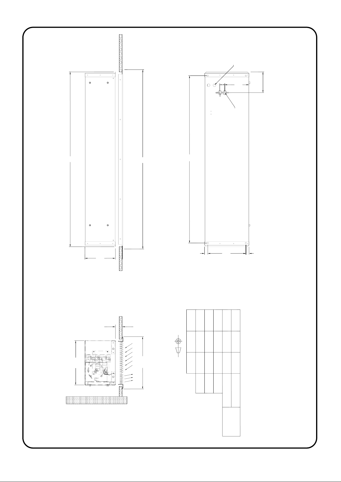
Electrical
supply inlet
33
165
1m-140
2m-150
1.5m-140
B
206
CEILING LEVEL
C
25-85mm
A
C2000R
2040
22
2090
LPHW connections
Rp 1/2 (1/2" BSP female)
257
22
301
Figure 1
1579
1529
C1500RC1000R
353
1179B(mm)
1129
A(mm)
15791179 2090
1209 1609 2120
C(mm)
Length(mm)
Cut-Out
311 311 311
Width(mm)
in Ceiling
4001150-6 Page 4 of 128

Safety and Electrical Connections
All electrical wiring and connections MUST be carried out by a competent qualified
electrician in accordance with the latest edition of the IEE wiring regulations and/or
local statutory regulations.
A single phase or 3 phase isolator with a contact separation of at least 3mm in all poles
must be fitted to the supply wiring (the isolator must be fitted in an accessible position).
The air curtain must be earthed.
The appliance must be connected using cables having an appropriate temperature
rating (heat resistant).
Ensure that the supply cables, circuit breakers and other electrical installation
equipment are correctly sized for the air curtain being installed; see Table 2.
On a 3 phase electrical supply the unit requires a neutral connection (3N~).
Cable glands used for the Electrical Input must be rated IP21 or higher.
Table 2
Air Curtain Electrical
Supply
Rated Power
Input (kW)
Current per
phase (A)
Heat Output
(kW)
Weight
(kg)
(V/ph/Hz)
C1000AR 230/1/50 0.15 0.7 N/A 19
C1500AR 230/1/50 0.20 0.9 N/A 25
C2000AR 230/1/50 0.25 1.1 N/A 35
C1000WR 230/1/50 0.15 0.7 6.0 20
C1500WR 230/1/50 0.20 0.9 9.0 27
C2000WR 230/1/50 0.25 1.1 12.0 37
C1000ER 400/3/50 9.15 13.7 4.5/9.0 22
C1500ER 400/3/50 12.20 18.3 6.0/12.0 30
C2000ER 400/3/50 18.25 27.2 9.0/18.0 41
Fitting/Connecting the Ecopower Remote Control (excluding Ambient)
The remote control unit should be located in
a suitable place for easy access, it can be
fixed to the wall via two key-hole slots. Drill
3.5mm
and fix the screws into the wall leaving a
small gap between the head and the wall,
lower the unit onto the screws, for fixing
80mm
6mm
centres see adjacent figure. Ensure
suitable fixing screws are used.
The remote control is supplied with 3m of cable and a pre-fitted RJ connecting plug.
Ensure the remote control cable is safely secured and connected.
4001150-6 Page 5 of 128
 Loading...