

Thermo Scientific Revco FDE30086FA, TDE30086FA, HDE30086FA, RDE30086FA, FDE30086FD Installation and Operation
...
Ultra-Low Temperature Freezers
TM
Revco
RDE Series, Forma
Series, HERAfreeze
Thermo Scientific
Installation and Operation
329712H01 • Revision A • March 2019
TM
TM
FDE
TM
HDE Series and
TDE Series

IMPORTANT Read this instruction manual. Failure to follow the instructions in this manual can result in
damage to the unit, injury to operating personnel, and poor equipment performance.
CAUTION All internal adjustments and maintenance must be performed by qualified service personnel.
Material in this manual is for informational purposes only. The contents and the product it describes are
subject to change without notice. Thermo Fisher Scientific makes no representations or warranties with
respect to this manual. In no event shall Thermo be held liable for any damages, direct or incidental, arising
from or related to the use of this manual.
© 2019 Thermo Fisher Scientific Inc. All rights reserved.

Contents
Models......................................................................... 1
Safety Considerations .................................................. 2
Unpacking ................................................................... 3
Packing List ............................................................. 3
General Recommendations.......................................... 4
Temperature Monitoring ........................................... 4
General Usage ......................................................... 4
Initial Loading ........................................................... 4
Battery Door Opening / Closing................................ 4
Operating Standards.................................................... 5
Electrical Specifications ............................................ 5
Installation.................................................................... 6
Location................................................................... 6
Leveling.................................................................... 6
Backup System (Optional) ........................................ 6
Super Insulated Cabinet Construction ...................... 6
Door Operation ........................................................ 6
Pressure Equalization Port........................................ 7
Installing the Remote Alarm Connector..................... 7
Intended Use............................................................ 7
Operation..................................................................... 8
Initial Start Up........................................................... 8
Operation Overview.................................................. 8
Display ..................................................................... 8
Settings.................................................................... 9

Power Down ............................................................ 10
Backup System (Optional)............................................ 11
CO2 and LN2 Precautions ....................................... 11
Installation ................................................................ 11
Start Up ................................................................... 12
Operation................................................................. 12
Chart Recorders (Optional)........................................... 13
Set Up and Operation .............................................. 13
Changing Chart Paper.............................................. 13
Calibration Adjustment ............................................. 13
Maintenance ................................................................ 14
Cleaning the Condenser........................................... 14
Cleaning the Condenser Filter................................... 14
Gasket Maintenance ................................................ 14
Defrosting the Freezer .............................................. 14
Battery Maintenance ................................................ 14
Maintenance Schedule............................................. 15
Troubleshooting Guide................................................. 16
Error Codes ................................................................. 19
Warranty ...................................................................... 20
Warranty (International) ................................................ 21
Appendix A: Alarm Summary ....................................... 22
Contact Information .................................................... 25

Models
Table 1. Applicable Models
Brand - Model Size (xxx) Voltage (*)
Forma - FDExxx86F* 300 / 400 / 500 / 600 A / D / V
Thermo Scientific –TDExxx86F* 300 / 400 / 500 / 600 A / D / V
HERAfreeze – HDExxx86F* 300 / 400 / 500 / 600 A / D / V
Revco - RDExxx86F* 300 / 400 / 500 / 600 A / D / V
Thermo Fisher Scientific ULT Freezers Models | 1
Safety Considerations
In this manual, the following symbols and conventions are
used:
This symbol used alone indicates important
operating instructions which reduce the risk of
injury or poor performance of the unit.
CAUTION: This symbol, in the context of a
CAUTION, indicates a potentially hazardous
situation which if not avoided could result in
minor to moderate injury or damage to the
equipment.
WARNING: This symbol indicates potentially
hazardous situations which, if not avoided, could
result in serious injury or death.
WARNING: This symbol indicates situations
where dangerous voltages exist and potential for
electrical shock is present.
The snowflake symbol indicates extreme low
temperatures and high risk of frostbite. Do not
touch bare metal or samples with unprotected
body parts.
Below are important safety precautions that apply to this
product:
Use this product only in the way described in the
product literature and in this manual. Before using
it, verify that this product is suitable for its
intended use. If this equipment is used in a
manner not specified by the manufacturer, the
protection provided by the equipment may be
impaired.
Do not modify system components, especially
the controller. Use OEM exact replacement
equipment or parts. Before use, confirm that the
product has not been altered in any way.
WARNING: Your unit must be properly grounded
in conformity with national and local electrical
codes. Never connect the unit to overloaded
power sources.
WARNING: Disconnect the unit from all power
sources before cleaning, troubleshooting, or
performing other maintenance on the product or
its controls.
This symbol indicates a need to use gloves during
the indicated procedures. If performing
decontamination procedures, use chemically
resistant gloves. Use insulated gloves for handling
samples and when using liquid nitrogen.
Before installing, using or maintaining this
product, please be sure to read this manual and
product warning labels carefully. Failure to follow
these instructions may cause this product to
malfunction, which could result in injury or
damage.
WARNING: “Caution, risk of fire”. This unit is
charged with hydrocarbon refrigerants.
2 | Safety Considerations Thermo Fisher Scientific ULT Freezers

Unpacking
At delivery, examine the exterior for physical damage while
the carrier’s representative is present. If exterior damage is
present, carefully unpack and inspect the unit and all
accessories for damage.
If there is no exterior damage, unpack and inspect the
equipment within five days of delivery. If you find any damage,
keep the packing materials and immediately report the
damage to the carrier. Do not return goods to the
manufacturer without written authorization. When submitting
a claim for shipping damage, request that the carrier inspect
the shipping container and equipment.
The packaging can be stored and re-used.
Packing List
Inside the freezer cabinet is a bag containing:
• A handle lock key
• A USB drive with user manual, including translated
versions
• Certificates of conformance and calibration
• A remote alarm contact connector
• Posts for rear spacing
If you have ordered a chart recorder, the bag will also contain:
• Recorder installation instructions
• Extra paper
If you have ordered a backup system, the cabinet will also
contain:
• A hose assembly
• English and metric connectors
If specified on the order, the bag may also include:
• A QC temperature graph and test log
• Calibration information
Thermo Fisher Scientific ULT Freezers Unpacking | 3
General Recommendations
Temperature Monitoring
IMPORTANT NOTE: Thermo Fisher Scientific
recommends the use of a redundant and
independent temperature monitoring system so
that the freezer can be monitored continuously
for performance commensurate with the value of
product stored.
General Usage
This refrigeration system is designed to maintain ultra-low
temperatures with safety in an ambient environment within
15°C to 32°C (59°F to 90°F), only when the freezer is used for
storage.
WARNING: This unit is not a “rapid-freeze”
device. Freezing large quantities of liquid, or highwater content items, will temporarily increase the
chamber temperature and will cause the
compressors to operate for a prolonged time
period.
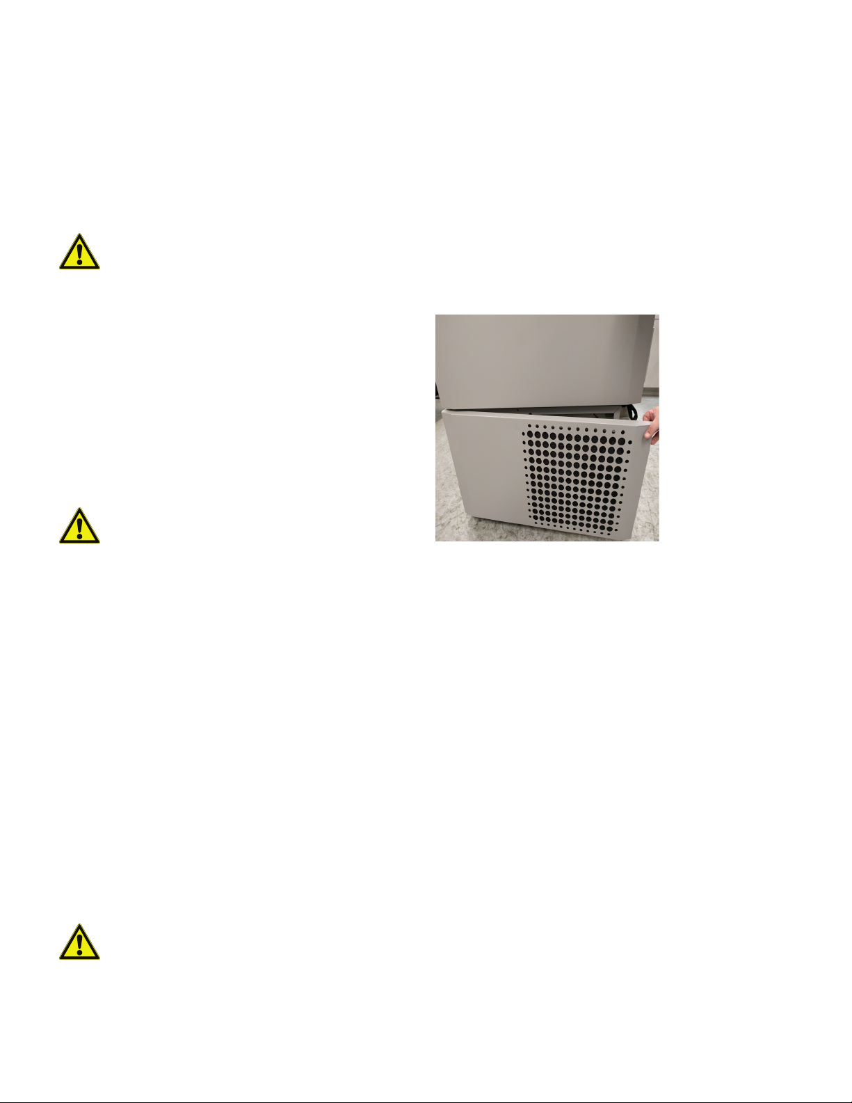
Battery Door Opening / Closing
To open the grille door, pull the door from the top right corner
as shown in the figure below.
To close the grille door, push the door against frame to hold
latch in position.
Figure 1. Door Opening
Avoid opening the door for extended time periods since
chamber temperature air will escape rapidly. Also, keep the
inner doors closed as much as possible. When room air,
which is higher in humidity, replaces chamber air, frost may
develop in the chamber more rapidly.
Initial Loading
Allow the freezer to operate at the desired temperature
for a minimum of 12 hours before loading.
Load the freezer one shelf at a time, beginning with the top
shelf. After loading each shelf, allow the freezer to recover to
the desired set point before loading the next shelf. Repeat this
process until the freezer is fully loaded.
CAUTION: Failure to follow these procedures or
overloading the unit may cause undue stress on
the compressors or jeopardize user product
safety.
4 | General Recommendations Thermo Fisher Scientific ULT Freezers

Operating Standards
The freezers described in this manual are classified for use as
stationary equipment in a Pollution Degree 2 and Over voltage
Category II environment.
These units are designed to operate under the following
environmental conditions:
• Indoor use
• Altitude up to 2000 m
• Maximum relative humidity 60% for temperatures within
15°C to 32°C (59°F to 90°F)
• Main supply voltage fluctuations not to exceed ±10% of
the nominal voltage.
Electrical Specifications
The last character in the model number listed on the dataplate identifies the electrical specifications for your unit.
Specific unit current rating is listed on the data-plate.
The voltage types are A, D and V as specified in the following
table:
Table 2. Electrical Specifications by Size and
Voltage
Size/
Vol t age
300A 115 V 60 Hz 12.6 A
300D 208-230 V 60 Hz 5.6 A
300V 230 V 50 Hz 5.9 A
400A 115 V 60 Hz 13.0 A
400D 208-230 V 60 Hz 5.9 A
400V 230 V 50 Hz 5.3 A
500A 115 V 60 Hz 12.5 A
500D 208-230 V 60 Hz 5.0 A
500V 230 V 50 Hz 5.9 A
600A 115 V 60 Hz 12.7 A
Voltage Frequency Current
600D 208-230 V 60 Hz 6.2 A
600V 230 V 50 Hz 6.1 A
Thermo Fisher Scientific ULT Freezers Operating Standards | 5

Installation
WARNING: Do not exceed the electrical rating
printed on the data plate located on the lower
left side of the unit.
Location
CAUTION: Never remove or disable the
grounding prong from the service cord plug. If the
prong is removed, the warranty is invalidated.
Leveling
Make sure that the floor is level. The unit must be level both
front to back and side to side.
The 300 and 400 box capacity models are equipped with one
or two leveling legs on the right hand side. Leveling legs on
300 size must be used as a safety precaution.
Install the unit in a level area free from vibration with a
minimum of 8" (20 cm) of space on the top and sides, 6" (15
cm) in back. Refer to Leveling for further instructions on
leveling cabinets. Allow enough clearance so that door can
swing open at least 85°.
The rear spacing posts provided with the freezer can be used
to ensure proper clearance. To install the spacing posts,
screw them into the back side of the unit, in the rear deck
area.
Do not position the equipment in direct sunlight or near
heating diffusers, radiators, or other sources of heat. The
ambient temperature range at the location must be 15°C to
32°C (59°F to 90°F).
Wiring
CAUTION: Connect the equipment to the
correct power source. Incorrect voltage can
result in severe damage to the equipment.
CAUTION: For personal safety and trouble-free
operation, this unit must be properly grounded
before it is used. Failure to ground the equipment
may cause personal injury or damage to the
equipment. Always conform to the National
Electrical Code and local codes. Do not connect
the unit to overloaded power lines.
CAUTION: Do not position the unit in a way that
impedes access to the disconnecting device or
circuit breaker in the back of the unit.
Ensure to lock the brakes for units equipped with casters.
Backup System (Optional)
If you are using a CO2 or LN2 backup system, refer to
Backup System (Optional) for installation and operation
instructions.
Super Insulated Cabinet Construction
In all models, the cabinet walls have a vacuum insulation core
encapsulated by a sealed film laminate.
CAUTION: Never drill holes in or near the cabinet
walls. Drilling could damage the insulation and
make the unit inoperable.
Door Operation
Upright freezer models are equipped with an advanced
assembly specifically designed for ultra-low temperature
freezers.
Features include:
• One-hand operation
CAUTION: Always connect the freezer to a
dedicated (separate) circuit. Each freezer is
equipped with a service cord and plug designed
to connect it to a power outlet which delivers the
correct voltage. Supply voltage must be within
±10% of the freezer rated voltage.
6 | Installation Thermo Fisher Scientific ULT Freezers
• A front-accessible lock
• Hasps for a standard padlock to provide additional
security. Length of the shackle must be between 3/4"
(1.9 cm) and 1 1/2" (3.8 cm)
• Durable construction for reliable operation and safe
product storage

• Door ramp alignment feature
Installing the Remote
CAUTION: When moving the freezer, always
grasp cabinet surfaces; never pull the freezer by
the latch handle.
Opening the Door
1. Remove the padlock if installed.
2. Grasp the latch handle and pull it toward yourself until the
latch disengages.
3. Keep pulling by the latch handle to open the main door.
Closing the Door
Note: The latch does not self-engage automatically when you
close the door. You must rotate the latch into the open
position first.
1. Grasp the latch handle and pull it toward yourself,
rotating the latch into the open position.
2. Move the freezer door into the closed position and gently
push the handle away from you, making sure that the
latch engages fully with the cabinet strike.
3. Keep applying gentle pressure to the latch handle until
the latch is securely in closed position.
4. Insert the key and rotate counterclockwise to lock.
5. Replace the padlock as required.
Alarm Connector
The remote alarm contacts are located on the back of the
freezer above and to the left of the power switch. After
installing the wiring from the remote alarm to the connector,
install the connector to the freezer micro-board.
The pin configuration is shown in Figure 2 below.
Figure 2. Remote Alarm Pin Configuration
For systems that alarm in closed state, connect to pins 5 & 6.
For systems that alarm in open state, connect to pins 6 & 7.
The contacts will trip in the event of a power outage, high
temperature alarm, low temperature alarm or door ajar alarm.
Pressure Equalization Port
When an upright ultra-low temperature freezer door is
opened, room temperature air rushes into the storage
compartment. When the door is closed, the fixed volume of
air is cooled rapidly. Pressure drops below atmospheric
pressure, resulting in a substantial vacuum. Re-entry into the
cabinet is impossible until internal pressures are returned to
atmospheric pressure. Without a pressure equalization
mechanism, it can take, in extreme cases, several hours
before the door can easily be reopened.
All upright models feature a port that provides vacuum relief
after door openings. The pressure equalization port is located
in the door behind the eye-level panel on the front of the
freezer. Although the port is heated and designed to selfdefrost, excessive frost accumulation on the inner door could
eventually restrict air flow. Therefore, you should periodically
inspect the inner door and brush away any loose frost using a
stiff nylon brush.
Thermo Fisher Scientific ULT Freezers Installation | 7
Intended Use
The –86°C freezer (refer to Models for the specific model
series) described in this manual are high performance units for
professional use. These products are intended for use as cold
storage in research use and as a general purpose laboratory
freezer, storing samples or inventory at operating
temperatures between –50°C and –80°C.
It is not considered a medical device and has therefore not
been registered with a medical device regulatory body (e.g.,
FDA): that is, it has not been evaluated for the storage of
samples for diagnostic use or for samples to be re-introduced
to the body.
This unit is not intended for use in classified hazardous
locations, nor to be used for the storage of flammable
inventory.

Operation
Initial Start Up
To start the freezer, complete the following steps:
1. Plug the freezer into the power outlet.
2. Turn the power switch ON. You can find the switch in
back of the freezer, on the bottom right.
3. Once the freezer is turned ON, the user interface will
begin a start up procedure. Once ready for operation, the
temperature is displayed on the screen.
Operation Overview
Once you have successfully completed the initial start up
procedures, the freezer starts operating normally and the only
actions required are:
• Setting the operating and alarm set points.
• Activating the CO
instructions on backup settings and activating the
system, refer to Backup System (Optional).
or LN2 backup system if installed. For
2
The control panel consists of the 5 touch-point buttons
located on the right side of the display.
1. Alarm Bell – This icon indicates visual and
audible alarm that accompanies various alarm
states. Pressing the alarm bell while in an alarm
state will snooze the audible alarm for 10
minutes.
2. Plus – Increases the value of the selected setting.
3.
4.
5.
• Warm Alarm value - The range of the warm alarm
Check Mark – Saves a change to the selected
value.
Minus – Decreases the value of the selected
setting.
Settings – The settings icon represents the
various settings including:
temperature is –40°C to within 5°C of setpoint.
Note : The warm alarm will be disabled for 12 hours
from a warm start condition.
Display
The display screen below is the default screen.
Figure 3. Display
• Cold Alarm value - The range is –99°C to within 5°C
of setpoint.
Note : A setpoint change may automatically change
the warm/cold alarm setpoints as well to maintain a
minimum 5°C separation from the control setpoint.
• Offset value - This is used for calibration. Range is
–10°C to +10°C. Default is 0.
Entering a positive offset value will yield a colder
cabinet temperature.
Entering a negative offset value will yield a warmer
cabinet temperature.
• Setpoint security code – This code is a 3-digit
numeric code. Refer to Setpoint Security.
• Backup system type (if backup system is installed)
– Set the type to either LN
the backup system that is installed.
• Backup system setpoint (if backup system is
installed) - This setpoint indicates the temperature at
which the backup system will begin cooling the cabinet. It is recommended to set the backup system
setpoint at a minimum of 10°C warmer than the con-
or CO2 corresponding to
2
8 | Operation Thermo Fisher Scientific ULT Freezers

trol setpoint. For more information, refer to Backup
System (Optional).
• Adjust the setting to desired temperature or value using
the plus or minus buttons
The message panel on the top indicates freezer health status
and the various alarm or warning states.
1. Wrench – This is a generic service warning which
corresponds to an intermittent flashing error code
displayed on the screen. Refer to Error Codes
for a list of error codes.
2. Door – This icon will illuminate when the door is
open. A door open for more than 3 minutes will
result in an audible alarm.
3. Heart – The heart is the health status for the
freezer. A green heart indicates normal freezer
operation. In an alarm state, this icon is not
illuminated.
4. Thermometer – This indicates when the cabinet
temperature exceeds either warm alarm or cold
alarm setpoints and the audible alarm will occur.
5. Snooze Bell – This is only illuminated during an
active alarm that has been silenced by the user.
• Press the checkmark button to save the new
temperature or value
• After the value is saved, display will show the next option
in the settings menu.
To return to the unit temperature display:
• Press the settings button until unit temperature is
displayed (“Actual” is illuminated)
• If there is no activity after 5 minutes, the unit will
automatically return to the temperature display.
Warm Alarm Test
Press the plus and checkmark buttons at the same time to
initiate the warm alarm test. During the warm alarm test, the
actual cabinet temperature will not be displayed. The display
temperature will increase. Once the display temperature
reaches the warm alarm setpoint, the alarm is activated. After
5 seconds, the test will automatically end and the display will
return to the actual cabinet temperature.
Settings
If setpoint security is enabled, you must first enter the security
code to make any setpoint changes. Refer to Setpoint
Security to adjust setpoint security.
Control Setpoint
To modify the control temperature setpoint:
• Press the plus or minus button while displaying unit
temperature (“Actual” is illuminated). The control setpoint
is displayed
• Adjust setpoint to desired temperature
• Select the checkmark button to save the new control
setpoint.
Other Setpoints and Settings
• Press the settings button to enter Settings menu
Setpoint Security
• To adjust setpoint security in the settings menu, press the
settings button 4 times
• The setpoint security code consists of 3 digits, each of
which must be set in sequence from left to right
• Use the plus or minus button to adjust each value, and
the checkmark button to save each value of the 3-digit
security code
• If you forget the setpoint security code, contact customer
support.
• Continue pressing the settings button until the desired
setting is illuminated on lower horizontal panel. (If backup
system is installed, CO
the settings button 5 times.)
Thermo Fisher Scientific ULT Freezers Operation | 9
or LN2 is displayed after pressing
2

Power Down
To power down the ULT, first turn the breaker switch, located
at the rear of the freezer, to the off position. Once the switch
is in the off position, the display will show "OFF" followed by
"YES" and then "NO" in 2 second intervals. The checkmark
will also be illuminated while "YES" and "NO" are showing.
Press the checkmark while "YES" is showing. With a flashing
"YES", you are required to confirm by pressing the checkmark
button a second time. Power down will then be complete.
If the checkmark button is pressed while "NO" is illuminated
or if no action is taken for 5 minutes, this is interpreted as a
power failure. In this case, the user interface will stay on (using
battery power only) and an audible alarm will sound to
indicate power failure. If installed, the backup system will
remain active and inject per the backup system settings.
10 | Operation Thermo Fisher Scientific ULT Freezers

Backup System (Optional)
For all ultra-low temperature cold storage products, we
recommend the use of a backup system (BUS) for the
security of your samples.
When you purchase a built-in CO
system for the freezer, backup control is integrated into the
main user interface.
Note: For stand-alone backup systems, refer to installation
instructions provided with the backup system kit.
Note: Always purchase the cylinders which are
equipped with siphon tubes for withdrawing liquid
from the bottom of the cylinder. CO
must be kept at room temperature to function
properly. LN
reasonable temperature.
bottles are functional at any
2
or LN2 optional backup
2
cylinders
2
CO2 and LN2 Precautions
The following are precautions for using liquid CO2 and LN2
backup systems.
WARNING: If a CO
valve is knocked off, the cylinder becomes a
deadly and completely unguided missile.
Transport the cylinders in a hand-truck or cart
with secure chain ties for the cylinder. After
cylinders are connected to the equipment,
securely attach them with chains to a solid
stationary object such as a building column.
or LN2 cylinder falls and a
2
CAUTION: When closing the cylinder valve,
make sure that the injection solenoid is energized
to allow all the liquid to bleed off instead of being
trapped in the supply hose. Failure to do this
results in activation of the pressure relief device,
which could damage the freezer and requires
replacing if it is activated.
CAUTION: For models ordered with factory
installed built-in backup systems, the flow of
liquid CO
is opened during operation of the backup
system. For units operated with free-standing,
field installed type backup system, the flow of
liquid CO
opening only if the switch provided with the freestanding package is installed on the freezer.
or LN2 will be discontinued if the door
2
or LN2 will be discontinued upon door
2
Installation
Field installed systems are supplied with complete installation
and operating instructions. If your system is factory installed,
the freezer is shipped with a coiled length of hose to connect
the freezer to the bottles:
• 1/4” Flexible Hose with fittings for connection to the CO
supply.
• 1/2” Flexible Hose with fittings for connection to the LN
supply.
To install,
1. Straighten the coiled hose.
2
2
WARNING: CO
poisonous but are very cold and will burn
unprotected skin. Always wear protective eye
wear and clothing when changing cylinders or
working on the piping systems attached to an
active source of liquid refrigerant.
WARNING: The gases produced by evaporation
of CO
or LN2 are non-poisonous but displace
2
the oxygen in a confined space and can cause
asphyxiation. Do not store the cylinders in
subsurface or enclosed areas.
Thermo Fisher Scientific ULT Freezers Backup System (Optional) | 11
and LN2 liquids are non-
2
2. Connect one end to the labeled connection on the
freezer.
• Tighten the nut two flats past finger tight, approximately
120 degrees.
Note: For CO
the end of the copper tubing to access nut for connection to
the freezer. Discard the threaded fitting.
3. Attach the other end to the supply bottle or building
supply fitting.
•For CO
• Remove Nipple from adapter (NPT Connection).
, remove the threaded fitting from the nut on
2
:
2
Remove cable tie to release alternative nut and
washer. Ensure the correct nut fitting is supplied over
the nipple (US or European).

• Add 2 wraps of Teflon tape clockwise to the 1/4”
NPT fitting (on the nipple) when viewed from the
threads. Tighten the NPT fittings approximately 2
turns from finger tight (approximately 720°).
Note : The top of the nipple has a hex configuration,
allowing for use of a wrench when the nut is pulled
down.
• Add washer to nipple inside of nut (unless CO
supply has a built in washer).
Note : Small raised area of washer fits into groove of
nipple. The washer will feel snug when trying to shift
side-to-side on nipple. The washers are designed for
a limited number of attachments/disconnections
from the supply and may wear over time. If washer
appears worn and causes CO
washer (Part Number 45705H03).
• Wrench tighten the supply nut to the supply.
leakage, replace
2
2
Operation
The backup system can run for a minimum of 24 hours on
battery power.
On average, a backup system in operation uses 8 to 10 lbs.
per hour of CO
ambient temperature of 25°C.
This rate will vary depending on set point, load, ambient
temperature and freezer size.
(3.6 to 4.5 L/hr) or LN2 (4.5 to 5.6 L/hr) at an
2
•For LN
• Attach the fitting to the supply and wrench tighten.
Note: Do not twist, torque, or subject the flexible hose to
sharp bends. Doing so may shorten the life of the hose.
:
2
Start Up
When the unit is started, it will recognize if a backup system is
installed.
1. Follow the instructions in Backup System (Optional) to
set the backup system type and setpoint.
2. It is recommended to test backup system operation prior
to sample storage.
Test BUS Operation
After the freezer has stabilized and both batteries are fully
charged, the BUS can be tested to verify proper operation.
1. Disconnect the AC power to the freezer by turning the
power switch off.
2. As the freezer warms up, verify the BUS injects at the
desired temperature. Displayed temperature may vary by
a few degrees from injection temperature due to the
differences in probe locations.
Note: On a monthly basis, it is recommended to test your
backup system, check the supply tank system levels, and
check the backup battery voltage.
12 | Backup System (Optional) Thermo Fisher Scientific ULT Freezers

Chart Recorders (Optional)
Panel-mounted six-inch seven-day recorders are available as
options for all freezer models except for the smaller (300 and
400 box capacity) models.
Set Up and Operation
To prepare the recorder to function properly, complete the
following steps:
1. Open the grille door to access the recorder.
2. Install clean chart paper (refer to Changing Chart
Paper).
3. Remove the plastic cap from the pen stylus or ink pen
and close the recorder door.
Recorder operation begins when the system is powered on.
The recorder may not respond until the system reaches
temperatures within the recorder’s range.
CAUTION: Do not use sharp or pointed objects
to depress the chart buttons. This may cause
permanent damage to the recorder.
Changing Chart Paper
To change the chart paper, complete the following steps:
1. Locate the pressure sensitive buttons at the front, upper
left of the recorder panel.
2. Press and hold the Change Chart button (#3) for one
second. The pen will move off the scale.
3. Unscrew the center nut, remove the old chart paper, and
install new chart paper. Carefully align the day and time
with the reference mark (a small groove on the left side of
the recorder panel).
4. Replace the center nut and hand tighten. Press the
Change Chart button again to resume temperature
recording.
Figure 4. Chart Recorder
Calibration Adjustment
This recorder has been accurately calibrated at the factory
and retains calibration even during power interruptions. If
required, however, adjustments can be made as follows:
1. Run the unit continuously at the control set point
temperature. Continue steady operation for at least two
hours to provide adequate time for recorder response.
2. Measure cabinet center temperature with a calibrated
temperature monitor.
3. Compare the recorder temperature to the measured
cabinet temperature. If necessary, adjust recorder by
pressing the left (#1) and right (#2) chart buttons.
Note: The stylus does not begin to move until the top center
button (#3) is held for five seconds.
Figure 5. Chart Buttons
Thermo Fisher Scientific ULT Freezers Chart Recorders (Optional) | 13

Maintenance
WARNING: Unauthorized repair of your freezer
will invalidate your warranty. Contact Technical
Service. See Contact Information for phone
numbers.
CAUTION: Maintenance should only be
performed by trained personnel.
Cleaning the Condenser
Clean the condenser at least every six months; more often if
the laboratory area is dusty.
To clean the condenser, complete the following steps:
1. Pull the grille door open.
2. Vacuum the condenser.
3. Inspect the filter cleanliness and clean as required.
4. Close the grille door.
Defrosting the Freezer
Defrost the freezer once per year or whenever the ice buildup
exceeds 3/8”. To defrost, complete the following steps:
1. Remove all products and place in another ULT freezer.
2. Turn off the freezer.
3. Open the outer door and all inner doors.
4. Let the freezer stand with doors open for at least 24
hours. This allows both the interior and foamed
refrigeration system to warm to room temperature.
5. Dispose of the ice and wipe out any water standing in the
bottom of the cabinet.
6. If there is freezer odor, wash the interior with a solution of
baking soda and warm water.
7. Clean the exterior with any common household cleaner.
8. Close the doors, restart the freezer and reload. Refer
Initial Loading to follow the instructions.
Battery Maintenance
Cleaning the Condenser Filter
Clean the condenser filters every two or three months.
1. Pull the grille door open.
2. Remove the filter.
3. Shake the filter to remove loose dust, rinse the filters in
clean water, shake the excess water from the filter, and
replace the filter.
4. Close the grille door.
Gasket Maintenance
Periodically check the gaskets around the door for punctures
or tears. Leaks are indicated by a streak of frost which forms
at the point of gasket failure. Make sure that the cabinet is
level (refer Leveling for leveling information).
Keep the door gaskets clean and frost free by wiping gently
with a soft cloth.
The freezer monitors the voltage status of the battery daily
and indicates the battery’s voltage via visual and auditory
alarm. Replace the battery as indicated by system alarms or
as necessary per individual status evaluation. Check the
battery connections regularly. Although not required, annual
battery replacement is recommended to ensure proper
battery status in the event of power failure.
For safety, it is recommended to power off the unit and
disconnect it from the power source before replacing the
battery. Battery terminals are color coded in red and black.
Ensure the corresponding colored wires are connected to the
matching color terminals on the battery. The battery is
installed with terminals oriented toward the condenser
compartment or hinge side of the freezer’s outer door (refer
Battery Specification). With proper installation, the red wire
should be connected to the rear battery (positive) terminal and
the black wire to the front (common) terminal.
Failure to properly connect the battery can damage electrical
components and potentially hinder normal operation of the
freezer. Consult a certified service technician if there are any
questions or concerns about battery maintenance.
14 | Maintenance Thermo Fisher Scientific ULT Freezers

Battery Specification:
Rechargeable sealed lead-acid battery, 12 V, 7.0 Amp Hr.
Replacement batteries can be purchased directly from
Thermo Fisher Scientific.
Figure 6. Battery Specification
Maintenance Schedule
Regular maintenance is important to keep the unit working
properly. Inspect/clean as directed in the manual.
Item Interval
To maintain proper closure of inner
Ice/Frost
build up
Gasket
Filter
Condenser
Battery
doors, remove any ice or frost build up
around the gasket, inner doors, and
breakers as necessary.
Periodically check the gaskets around
the door for punctures or tears.
Periodically clean the ice-build up
around the gasket.
Clean the condenser filter(s) every two to
three months.
Clean every six months, more often if the
laboratory area is dusty.
Replace the battery as indicated by
system alarms or as necessary per
individual status evaluation. Check the
battery connections regularly. Although
not required, annual battery replacement
is recommended to ensure proper
battery status in the event of power
failure.
Defrost
Thermo Fisher Scientific ULT Freezers Maintenance | 15
Defrost the freezer once a year or when
the ice build exceeds 3/8” (0.95 cm)

Troubleshooting Guide
This section is a guide to troubleshoot general operational problems.
Problem Cause Solution
Unit warming.
Unit set to –80°C but can’t
make temperature (Not
reaching set point).
Unit recovers slowly to set
point.
Warm load / Over load.
Hot environment.
Dirty condenser and
condenser filter.
Not enough space for air
circulation.
Icing/Frost due to high
relative humidity.
Excess frost build-up in
chamber.
Frost build-up on outer
door gasket.
Gasket damage.
Allow ample time to recover from loading warm product.
Do not overload cabinet. Refer Initial Loading in user
manual for loading procedures.
Check, if the location meets ambient requirements (within
15°C to 32°C or 59°F to 90°F) and away from hot objects.
Clean condenser and filter. Refer Cleaning the
Condenser and Cleaning the Condenser Filter in user
manual.
Install the unit in a level area free from vibration with a
minimum of 8" (20 cm) of space on the top and sides, 6"
(15 cm) in back.
Check if the location meets requirements. Maximum
relative humidity 60% for temperatures within 15°C to
32°C (59°F to 90°F).
Defrost the unit. Refer Defrosting the Freezer in user
manual.
Occasionally scrape the ice on the gasket. Do not use a
sharp tool. Be careful not to puncture the rubber gasket.
Check for punctures or tears on gasket. Replace if
necessary. Refer Gasket Maintenance in user manual.
Prolonged door openings.
Inadequate power supply. Check for proper voltage to the unit.
Either of the compressors
are not working.
User interface (Display)
failure.
Power failure to the unit.
16 | Troubleshooting Guide Thermo Fisher Scientific ULT Freezers
Breaker switch off.
Power supply stopped /
Breaker switch off.
Avoid opening of door for a prolonged time. Allow ample
time for recovery after door opening.
Call service.
Check circuit breaker and reset to on position. Always
use a dedicated, properly grounded circuit.
Confirm that the cord is securely plugged in.
Plug another appliance into the outlet to see if power is
present.
Always use a dedicated, properly grounded circuit.

Problem Cause Solution
Unit tripping the circuit
breaker.
Excessive frost build-up
around perimeter of door.
Shared power source.
Unit plugged into wrong
power outlet.
Unit not grounded.
Use of extended cords.
Icing/Frost due to high
relative humidity.
Excessive and prolonged
door openings.
Gasket damage.
Never connect unit to overloaded power source. Always
use a dedicated (separate) circuit.
Plug the unit into proper power source to deliver correct
voltage.
Your unit must be properly grounded in conformity with
national and local electrical codes. Troubleshooting
procedures involving live voltage is dangerous and if
done improperly can result in injury and/or death. This
troubleshooting should be performed by trained
personnel only.
Do not use an extension cord. Make sure the unit
supplied power cord is plugged directly into power outlet.
Check if the location meets requirements. Maximum
relative humidity 60% for temperatures within 15°C to
32°C (59°F to 90°F).
Occasionally scrape the ice on the outer door.
Be careful not to puncture the rubber gasket.
Avoid opening door for a prolonged time.
Check for punctures or tears on gasket. If replacement is
necessary, call service. Refer Gasket Maintenance in
user manual.
Unit is over cooling.
Unit compressors run
continuously.
Cabinet temperature reached
an alarm condition, but
suitable alarm is
activated.
not
Set points may have
changed.
Temperature offset may
have changed.
Unknown. Try re-starting the unit. If this doesn’t help call service.
Freezer set point is low.
Frost build up.
Dirty condenser. Clean the condenser and condenser filter.
Gasket damage.
Alarm setpoints may be
changed.
Adjust the setpoint to run at desired setpoint under
settings.
Try adjusting the offset. Temperature offset can be set by
accessing the settings menu via the settings button.
Check whether the setpoint is in operating range. Change
the setpoint if necessary.
Defrost the unit. Refer Defrosting the Freezer in user
manual.
Check for punctures or tears on gasket. If replacement is
necessary, call service. Refer Gasket Maintenance in
user manual.
Check the present setpoints for temperature alarm
conditions. Change the setpoints if required.
Thermo Fisher Scientific ULT Freezers Troubleshooting Guide | 17

Problem Cause Solution
Customers performing on-site temperature calibration
may observe as much as a 2°C variation when an external
probe is placed next to the freezer control probe. This
variation is normal due to optimisation of the control
system to ensure temperature uniformity throughout the
cabinet.
Problem with temperature
validation/calibration.
Cabinet temperature
displayed doesn’t match
with actual temperature.
Unit is constantly alarming.
Unit cycle on-percentage is
increasing (Compressors are
running more often than
before).
Difficult to close / open the
outer door.
Outer door alignment issues.
Exterior door is closed but
not sealed completely.
Door open alarm, exterior
door not closing
completely.
Door open alarm, exterior
door is closed but not
sealed completely.
Alarm set points may have
changed.
Ambient conditions. Unit performance is directly impacted by these causes
Warm load (or) over load.
Frequent and prolonged
door openings.
Unit is not level.
Frost accumulated on
outer door gasket.
Door latch problem.
Clean any ice build-up on gasket and/or cabinet surface.
Check for punctures or tears on gasket.
Open door completely and immediately close and latch it.
Defrost exterior door gasket and make sure the door is
completely sealed.
Change the set points as required.
mentioned. Try maintaining ambient conditions, reducing
load, reducing door openings.
Once temperature is stable, cycle dynamics should return
to normal range. If not call service.
Make sure the unit is level.
Refer Leveling in the user manual for levelling procedure.
Scrape the ice occasionally on outer gasket.
Do not puncture gasket.
Ensure door latch is securing. If issue persists, call
service.
Frost accumulated around
Difficult to close / open the
inner door.
Vibration noise.
Rattling noise/ Loud noise.
18 | Troubleshooting Guide Thermo Fisher Scientific ULT Freezers
inner door.
Inner door latches
damaged.
Unit is not level.
Loose side panels. Check side panel screws, tighten them if necessary.
Rubber tubing separators
and/or compressor
dampeners may have
loosened.
Remove frost or ice build-up from inner door assembly.
Call service.
Check if the unit is installed in a level area free from
vibration. (Refer Leveling in user manual)
Call service.

Error Codes
Error Code Description
E00 Undefined model
E01 Firmware Build Incompatible
E02 Control Probe Failure
E03 Heat Exchanger Probe Failure
E04 Power Failure
E05 Failure to Reach Setpoint
E06 BUS Battery Failure
E07 System Battery Failure
E08 Lost Communication Failure (Main to UI)
E09 Lost Communication Failure (BUS)
E10 Stuck Button
E11 Ambient Probe Failure
Thermo Fisher Scientific ULT Freezers Error Codes | 19

Warranty
Be sure to register your warranty online:
www.thermofisher.com/labwarranty
THERMO FISHER SCIENTIFIC USA FREEZER WARRANTY
FOR Revco RDE series, Forma FDE series, HERAfreeze HDE
series and Thermo Scientific TDE series
The Warranty Period starts two weeks from the date your
equipment is shipped from our facility. This allows for shipping
time so the warranty will go into effect at approximately the
same time your equipment is delivered. The warranty
protection extends to any subsequent owner during the
warranty period.
Component parts proven to be non-conforming in materials
or workmanship will be repaired or replaced at Thermo Fisher
Scientific's expense, labor included, for a period of five years.
Installation and calibration is not covered by this warranty
agreement. The Technical Services Department must be
contacted for warranty determination and direction prior to
any work being performed. Expendable items, i.e., glass,
filters, pilot lights, light bulbs and door gaskets are excluded
from this warranty.
Replacement or repair of component parts or equipment
under this warranty shall not extend the warranty to either the
equipment or to the component part beyond the original five
year warranty period. The Technical Services Department
must give prior approval for the return of any components or
equipment.
THIS WARRANTY IS EXCLUSIVE AND IN LIEU OF ALL
OTHER WARRANTIES, WHETHER WRITTEN, ORAL, OR
IMPLIED. NO WARRANTIES OF MERCHANTABILITY OR
FITNESS FOR A PARTICULAR PURPOSE SHALL APPLY.
Thermo shall not be liable for any indirect or consequential
damages including, without limitation, damages relating to
lost profits or loss of products.
Your local Thermo Fisher Scientific Sales Office is ready to
help with comprehensive site preparation information before
your equipment arrives. Printed instruction manuals carefully
detail equipment installation, operation, and preventive
maintenance.
If equipment service is required, please call your Technical
Services Department at 1-866-984-3766 (USA and Canada).
We're ready to answer your questions on equipment
warranty, operation, maintenance, service, and special
applications. Outside the USA, contact your local Thermo
Fisher Scientific office or distributor for warranty information.
20 | Warranty Thermo Fisher Scientific ULT Freezers

Warranty (International)
THERMO FISHER SCIENTIFIC FREEZER INTERNATIONAL
WARRANTY FOR Revco RDE series, Forma FDE series,
HERAfreeze HDE series and Thermo Scientific TDE series
The Warranty Period starts two months from the date your
equipment is shipped from our facility. This allows for shipping
time so the warranty will go into effect at approximately the
same time your equipment is delivered. The warranty
protection extends to any subsequent owner during the
warranty period. Dealers who stock our equipment are
allowed an additional four months for delivery and installation,
providing the warranty card is completed and returned to the
Technical Services Department.
Component parts proven to be non-conforming in materials
or workmanship will be repaired or replaced at Thermo Fisher
Scientific's expense, labor excluded, for a period of five years.
Installation and calibration is not covered by this warranty
agreement. The Technical Services Department must be
contacted for warranty determination and direction prior to
any work being performed. Expendable items, i.e., glass,
filters, pilot lights, light bulbs and door gaskets are excluded
from this warranty.
Replacement or repair of component parts or equipment
under this warranty shall not extend the warranty to either the
equipment or to the component part beyond the original five
year warranty period. The Technical Services Department
must give prior approval for the return of any components or
equipment.
THIS WARRANTY IS EXCLUSIVE AND IN LIEU OF ALL
OTHER WARRANTIES, WHETHER WRITTEN, ORAL, OR
IMPLIED. NO WARRANTIES OF MERCHANTABILITY OR
FITNESS FOR A PARTICULAR PURPOSE SHALL APPLY.
Thermo shall not be liable for any indirect or consequential
damages including, without limitation, damages relating to
lost profits or loss of products.
Your local Thermo Fisher Scientific Sales Office is ready to
help with comprehensive site preparation information before
your equipment arrives. Printed instruction manuals carefully
detail equipment installation, operation, and preventive
maintenance.
If equipment service is required, please contact your local
Thermo Fisher Scientific office or local distributor.
We're ready to answer your questions on equipment
warranty, operation, maintenance, service, and special
applications. Outside the USA, contact your local Thermo
Fisher Scientific office or distributor for warranty information.
Thermo Fisher Scientific ULT Freezers Warranty (International) | 21

Appendix A: Alarm Summary
Alarm Summary
Alarm Message
Warm Alarm Thermometer Yes
Cold Alarm Thermometer Yes
Door Open Ajar Door Yes
Control Probe
Failure
Heat Exchange
Probe Failure
Ambient Probe
Failure
Warning
Icon
Wrench Yes
Wrench Yes
Wrench Yes
Remote
Alarm Event
Description
The freezer temperature has exceeded the warm alarm set
point.
Prolonged door openings and warm product loading may
cause warm alarms.
The freezer temperature has exceeded the cold alarm set
point.
Door open for greater than 3 minutes will cause door open
alarm.
Cannot display cabinet temperature. The freezer will
continue to operate in full run mode. Contact customer
service.
Display will intermittently show "E02".
The freezer will continue to operate with current freezer
setpoints, but cabinet temperature variation will increase.
Contact customer service.
Display will intermittently show "E03".
Ambient Probe TC has malfunctioned. This doesn't affect
the performance of the unit. Contact service for further
assistance.
Display will intermittently show "E11".
Main to UI Lost
Communication
BUS Lost
Communication
Failure to Reach
Set point
Power Failure Alarm Wrench Yes
22 | Appendix A: Alarm Summary Thermo Fisher Scientific ULT Freezers
Wrench Yes
Wrench Yes
Wrench Yes
A communication error has occurred within the system.
Contact customer service.
Display will intermittently show "E08".
A communication error has occurred within the backup
system. Contact customer service.
Display will intermittently show "E09".
Door openings or product loading may cause this
notification. Allow unit to stabilize. If condition persists,
contact customer service.
Display will intermittently show "E05".
Unit in power failure mode.
Display operating on battery power. Check unit plug, unit
circuit breaker in the ON position, and supply voltage.
Display will intermittently show "E04".

Alarm Summary
Alarm Message
Wrong Model Alarm Wrench Yes
Firmware Build
Incompatible
System Battery
Failure Alarm
Bus Battery
Failure Alarm
Stuck Button Alarm Wrench Yes
Warning
Icon
Wrench Yes
Wrench Yes
Wrench Yes
Remote
Alarm Event
Description
Invalid Control Model Alarm. Contact service to ensure the
correct model is selected for the system to avoid cargo
loss.
Display will intermittently show "E00".
Firmware build indicates incompatibility that can result in
modules to be non-coherent.
Display will intermittently show "E01".
System Battery Disconnected or Failed.
Display will intermittently show "E07".
BUS Battery Disconnected or Failed
Display will intermittently show "E06".
A button has been pressed for more than 5 minutes.
Display will intermittently show "E10".
Thermo Fisher Scientific ULT Freezers Appendix A: Alarm Summary | 23

WEEE Compliance
Great Britain
Deutschland
Italia
France
WEEE Compliance. This product is required to comply with the European Union’s Waste
Electrical & Electronic Equipment (WEEE) Directive 2012/19/EU. It is marked with the
following symbol. Thermo Fisher Scientific has contracted with one or more
recycling/disposal companies in each EU Member State, and this product should be
disposed of or recycled through them. Further information on our compliance with these
Directives, the recyclers in your country, and information on Thermo Scientific products
which may assist the detection of substances subject to the RoHS Directive are available at
www.thermofisher.com/WEEERoHS.
WEEE Konformittät. Dieses Produkt muss die EU Waste Electrical & Electronic
Equipment (WEEE) Richtlinie 2012/19/EU erfüllen. Das Produkt ist durch folgendes
Symbol gekennzeichnet. Thermo Fisher Scientific hat Vereinbarungen getroffen mit
Verwertungs-/Entsorgungsanlagen in allen EU-Mitgliederstaaten und dieses Produkt muss
durch diese Firmen widerverwetet oder entsorgt werden. Mehr Informationen über die
Einhaltung dieser Anweisungen durch Thermo Scientific, dieVerwerter und Hinweise die
Ihnen nützlich sein können, die Thermo Fisher Scientific Produkte zu identizfizieren, die
unter diese RoHS. Anweisungfallen, finden Sie unter www.thermofisher.com/WEEERoHS.
Conformità WEEE. Questo prodotto deve rispondere alla direttiva dell’ Unione Europea
2012/19/EU in merito ai Rifiuti degli Apparecchi Elettrici ed Elettronici (WEEE).
È marcato col seguente simbolo.Thermo Fischer Scientific ha stipulato contratti con una o
diverse società di riciclaggio/smaltimento in ognuno degli Stati Membri Europei. Questo
prodotto verrà smaltito o riciclato tramite queste medesime. Ulteriori informazioni sulla
conformità di Thermo Fisher Scientific con queste Direttive, l’elenco delle ditte di
riciclaggio nel Vostro paese e informazioni sui prodotti Thermo Scientific che possono
essere utili alla rilevazione di sostanze soggette alla Direttiva RoHS sono disponibili sul sito
www.thermofisher.com/WEEERoHS.
Conformité WEEE. Ce produit doit être conforme à la directive euro-péenne
(2012/19/EU) des Déchets d’Equipements Electriques et Electroniques (DEEE). Il est
marqué par le symbole suivant. Thermo Fisher Scientific s’est associé avec une ou plusieurs
compagnies de recyclage dans chaque état membre de l’union européenne et ce produit
devraitêtre collecté ou recyclé par celles-ci. Davantage d’informations sur laconformité de
Thermo Fisher Scientific à ces directives, les recycleurs dans votre pays et les informations
sur les produits Thermo Fisher Scientific qui peuvent aider le détection des substances
sujettes à la directive RoHS sont disponibles sur www.thermofisher.com/WEEERoHS.

Contact Information
Thermo Fisher Scientific products are backed by a global technical support team ready to support your applications. We offer
cold storage accessories, including remote alarms, temperature recorders, and validation services.
Visit www.thermofisher.com/cold or call:
Countries Sales
North America +1 866 984 3766
India toll free 1800 22 8374
India +91 22 6716 2200
China +800 810 5118, +400 650 5118
Japan +81 3 5826 1616
France +33 2 2803 2180
Germany international +49 6184 90 6000
Germany national toll free 0800 1 536 376
UK/Ireland +44 870 609 9203
r countries not listed here, visit www.thermofisher.com and go to the Contact Us page under the Services menu to locate the
Fo
ntact information for your area.
co
Thermo Fisher Scientific Inc.
275 Aiken Road
Asheville, NC 28804
United States
Find out more at thermofisher.com/cold
2019 Thermo Fisher Scientific Inc. All rights reserved. All trademarks are the property of
©
Thermo Fisher Scientific and its subsidiaries unless otherwise specified. 329712H01 0319
 Loading...