

Thermo Scientific picoSpin picoSpin-45 Quick Start

Quick Start
The picoSpin-45 NMR spectrometer is a complete 45 MHz pulsed Fourier-transform liquid-phase
proton NMR spectrometer in a shoebox-sized package. It includes a capillary cartridge, a permanent
magnet with temperature controller and shim system, radio-frequency transmitters and receivers,
digital data acquisition and signal processing, a programmable pulse sequencer, and a web-server
user interface.
In most respects, the picoSpin-45 hardware components have functions similar to the components of
a conventional superconducting-magnet NMR spectrometer. Apart from drastically lower cost and
size, the main differences are that the magnet is permanent rather than superconducting and the
sample is delivered by flow through a capillary rather than by inserting a glass NMR tube. Operation
is greatly simplified because there is no need to handle cryogens or other utilities, tuning and
shimming are not required when samples are changed and there is no software installation required
to set up the system. Users can produce high-resolution spectra with a new unit a few hours after the
shipping package is opened. In normal operation, samples can be injected into the system and
spectroscopic data can be obtained in less than 10 minutes.
This Quick Start assumes that the user is setting up a newly-received instrument. It will also be
helpful to a user who is becoming familiar with a unit that has already been set up for operation. In
this case it will be possible to skip many of the steps. If the unit is already set up to communicate
with a web browser, temperature stabilized, shimmed adequately and the Larmor frequency is
known, skip to
Injecting a Sample
and then read
Your First Spectrum
.
What’s in the Box
Inside the shipping box you will find the following items:
picoSpin-45 spectrometer
+12 V modular power supply
power cord
Ethernet cable
accessory packet
factory test report
1 of 13
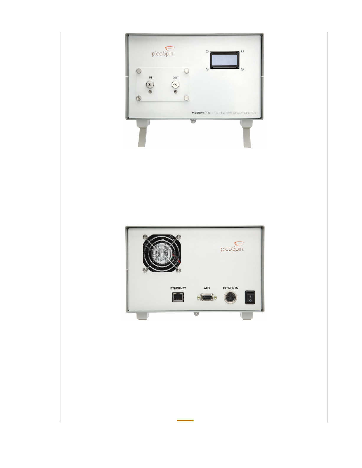
Front panel
The fluid sub-panel, mounted on the left side of the front panel with four thumb screws, is a part of
the replacable capillary cartridge. Do not remove the cartridge at this time. (When a cartridge
is replaced the unit has to be shimmed. It is better to gain some experience with the unit and with
shimming before replacing a cartridge.) The unit is delivered with the inlet and outlet fittings covered
with protective tape. You will notice that the inlet fitting has a double nut. A stainless steel frit filter is
held in place by the smaller, outer nut.
The LCD display on the upper right of the front panel is used to monitor the status of the instrument.
Rear panel
On the rear panel you will see an Ethernet connector, an auxilliary output connector, a power input
connector and an on/off switch. The auxilliary output is intended for controlling external hardware
such as valves.
The test report includes the spectrometer and cartridge serial numbers, the shipped software
version, the shim settings that were used for factory tests, a screen shot of the free-induction-decay
signal of water, and a screen shot showing a measurement of the signal-to-noise ratio.
Ethernet Connection
The first step is to establish communication with the spectrometer using a computer and a standard
web browser. We recommend Mozilla’s free Firefox web browser for best compatiblity with our
2 of 13

software. Any type of computer with an Ethernet port can be used. There are two options for making
the initial connection: through a LAN (local area network) with the IP address of the spectrometer
assigned by the LAN, or by a direct connection between the spectrometer and your computer
without using any network. Connection through a LAN is more convenient in most cases. However, if
you do not have a LAN, do not have access to an open Ethernet port on your LAN, or if your LAN
cannot assign IP addresses using DHCP (dynamic host configuration protocol), then you should use a
direct connection.
Connect the power cord to the power module and connect the multi-pin connector from the power
module to the power input connector on the rear panel. The multi-pin connector has a threaded
collar that should be tightened by hand to secure the connector to the rear panel. Check that the
rear panel power switch is in the off (down) position and plug the power cord into an AC power
source.
Connecting through a LAN
Connect the the unit to an available Ethernet port on your LAN using the Ethernet cable provided, or
a longer cable if necessary. Switch on the unit while watching the front panel LCD display. After about
one minute an IP address should appear on the front panel. This address has been assigned by your
LAN using DHCP. (See below if the address displayed is 192.168.42.31.) Point a web browser at the
address and you will see the welcome screen shown below. (For example, if the address displayed is
192.168.2.12, type http://192.168.2.12 into the address field of the browser.)
Welcome screen (click to enlarge)
Automatic assignment of the IP address by the LAN will only be successful if the unit is switched on
after
it has been connected to an active Ethernet port on your LAN, and then only if your LAN has
DHCP capability. If the unit is not assigned an IP address by DHCP it will display a factory default IP
address of 192.168.42.31. In most cases, you will not be able to communicate through your LAN to
this address because LANs are configured so they can only communicate with a sub-set of all IP
addresses. For example, your LAN might only allow communication between IP addresses of the form
192.168.2.xx, where xx is a number between 0 and 255. If you see the default IP address and you
are sure that your LAN does support DHCP, try using the same cable to connect another device to
the LAN Ethernet port you have chosen to make sure it is active. If you are unable to connect to the
spectrometer through your LAN, make a direct connection as descibed below.
Direct Connection
The computer must have an available Ethernet port with a working network adapter. If you are
unsure if the Ethernet port is working, try using it to connect to a network. Turn the spectrometer
3 of 13

power switch on
before
connecting it to the computer with the Ethernet cable. After about a minute,
the front panel LCD display will show the factory default IP address of 192.168.42.31. Now connect
the computer to the spectrometer using the provided Ethernet cable. Configure the Ethernet port on
the computer so that it can communicate with the default IP address. (To do this, you must set the IP
address of the computer to another address on the same sub-net. For example, you could set the
sub-net mask to 255.255.255.0 and the IP address to 192.168.42.10.) The details of setting up
Ethernet ports and network adapters on different computers vary widely. Consult your computer’s
documentation or your IP support staff if you need help. Once the port has been set up, type
http://192.168.42.31 into the address field of your browser to see the welcome screen shown
above.
After the welcome screen has been displayed for a moment, it will be replaced by the
Run
page,
which is used to enter experiment parameters, start experiments and monitor their progress. The
orange text links at the upper right of the page are used to navigate between pages. Go to the
Settings
page and click on
About This pS45
to find the current installed software version. If the
installed software version is not the same as the documentation you are reading, go to the picoSpin
web site and get the documentation for the software version you are using. Do not click on the
System Update link at this time. We recommend that you do not update the software on
a new unit until after you have verified correct operation by following the steps in the
Quick Start guide. This will reduce confusion if it becomes necessary to communicate with
picoSpin support staff, because you will be using the same software version that was used to
generate the factory test report.
Magnet Temperature Control
The permanent magnet in the picoSpin-45 has a magnetization temperature coefficient of about
-700 ppm/C. As a consequence, the stabilty of the instrument depends upon high-resolution control
of the magnet temperature. The controller can stabilize the magnet temperature to better than one
milli-degree over a period of several hours and to higher accuracy over shorter times.
Click on the
Temperature
link at the upper right to go to the temperature controller page. Also click
on the
Controller
button near the top of the page to display the temperature controller settings. The
screen shot below shows the temperature page after the temperature is fully stabilized.
4 of 13
 Loading...