

Thermo Scientific Lindberg BF51894C, BF51866A, BF51848A, BF51828C Instruction Manual

© 2011 Thermo Fisher Scientific Inc. All rights reserved.
These operating instructions are protected by copyright. Rights resulting thereof, particula rly reprint, photomechanical or digital postprocessing or reproduction, even in part, are only allowed with the written consent of Thermo Fisher Scientific.
This regulation does not apply to reproductions for in-plant use.
The contents of this operating instructions manual may change at any time and without any prior notice.
Concerning translations into foreign languages, the English version of these operating instructions is binding.
Trademarks
Linderberg/Blue M is a brand owned by Thermo Fisher Scientific Inc.
All other trademarks mentioned in the operating instructions are the exclusive property of the respective
manufacturers.
Thermo Electron LED GmbH
Robert-Bosch-Straße 1
D - 63505 Langenselbold
Germany
Thermo Electron LED GmbH is an affiliate to:
Thermo Fisher Scientific Inc.
81 Wyman Street
Waltham, MA 02454
USA
Thermo Fisher Scientific Inc. provides this document to its customers with a product purchase to use in
the product operation. This document is copyright protected. and any reproduction of the whole or any
part of this document is strictly prohibited, except with the written authorization of Thermo Fisher
Scientific Inc.
The contents of this document are subject to change without notice.
All technical information in this document is for reference purposes only. System configurations and
specifications in this document supersede all previous information received by the purchaser.
Thermo Fisher Scientific Inc. makes no representations that this document is complete, accurate
or error-free and assumes no responsibility and will not be liable for any errors, omissions,
damage or loss that might result from any use of this document, even if the information in the
document is followed properly.
This document is not part of any sales contract between Thermo Fisher Scientific Inc. and a purchaser.
This document shall in no way govern or modify any Terms and Conditions of Sale, which Terms and
Conditions of Sale shall govern all conflicting information between the two documents.
ii Heratherm Thermo Scientific

Table of Contents
Chapter 1 Safety Notes
Basic Operating Precautions............................................................................................................1-1
Safety Consideration........................................................................................................................1-2
Warranty........................................................................................................................................... 1-4
Material Safety Data Sheet ..............................................................................................................1-4
Explanation of Safety Information and Symbols................ ... ... .... ... ... ... ... .... ................................... 1-11
Additional Symbols for Safety Information ..................................................................................... 1-11
Standards and Directives...............................................................................................................1-12
Chapter 2 Introduction
Feature and Benefits........................................................................................................................2-1
Specifications................................................................................................................................... 2-2
Chapter 3 Pre-Installation
Unpacking ........................................................................................................................................3-1
Operating Condition ......................................................................................................................... 3-1
Atmosphere System.........................................................................................................................3-1
C
Chapter 4 Installation
Location............................................................................................................................................ 4-1
Wiring...............................................................................................................................................4-1
240 VAC Operation.................................... ... ................................................. ..................................4-2
BF51828C Models............................................................................................................................ 4-3
Exhaust Vent........... ... ... ... .... ... ... ................................................. ... ... ... ............................................4-4
Exhaust Port Connection......................... ... ... ................................................. ... ... .... ........................4-5
Atmosphere Inlet.............................................................................................................................. 4-6
Atmosphere Inlet Port.......................................................................................................................4-6
Hearth Plate Information ......................................... ................................................. ........................4-7
Guidelines for Ashing Application..................................................................................................... 4-7
Chapter 5 Start Up
Furnaces Start-up............................................................................................................................. 5-2
Door Seal Check..................................... ... ... .... ... ... ................................................. ........................5-3
Door Seal Adjustment .......... ... ... ... .... ... ................................................ ... .... ... .................................. 5-3
Door Latch Plate Adjustment................................................................... ......................................... 5-5
UP150 Controller Operation.............................................................................................................5-6
Ramp to 200 °C................................................................................................................................5-7
Ramp to 500 °C................................................................................................................................5-9
Ramp to 1000 °C And Operating for 2 hours .................................................................................5-10
Chapter 6 UP150 Control Overview
UP150 Control Overview .................................................................................................................6-2
Single Setpoint Operation. ......... ... .... ... ... ... ... .... ... ... ... .... ... ... ... ......................................................... 6-7
Programming operation: Entering a Program...................................................................................6-9
Using Hold Function ............... ... ... .... ... ... ... ... ................................................. ... ... .... ......................6-14
Using Advance Function ........ ... ... .... ... ... ................................................ .... ... ... ... .... ... ... ... .............6-14
Thermo Scientific i

Table of Contents
Auto Tuning through UP150 Controller..........................................................................................6-15
Temperature Offset Procedure.......................................................................................................6-16
Changing Temperature Scale Between °C and °F.........................................................................6-17
Chapter 7 Communication
Cable Installation..............................................................................................................................7-1
Communication Setup Parameter....................................................................................................7-1
Software Installation.........................................................................................................................7-2
Communication test.......................................................................................................................... 7-3
Troubleshooting................................................................................................................................ 7-4
Decimal Point Adjustment................................................................................................................7-4
Addresses for Multiple Controllers ................................................................................................... 7-4
Chapter 8 Maintenance
Door Seal Adjustment. ......... ... ... ... .... ... ... ................................................ .... ... ... ...............................8-2
Thermocouple Replacement............................................................................................................8-2
Solid State Relay Replacement........................................................................................................ 8-4
Power Relay Replacement...............................................................................................................8-5
Temperature Controller Replacement..............................................................................................8-5
Door Insulation Replacement.................. ... ... .... ...............................................................................8-6
Heating Unit Replacement. ..............................................................................................................8-7
Chapter 9 Troubleshooting .............................................................................................................9-1
Chapter 10 Wiring Diagram............................................................................................................. 10-1
Chapter 11 Replacement Parts ....................................................................................................... 11-1
Chapter 12 Error Codes...................................................................................................................12-1
Chapter 13 WEEE Compliance........................................................................................................ 13-1
Chapter 14 Spare Parts and Accessories......................................................................................14-1
Chapter 15 Device Log..................................................................................................................... 15-1
Chapter 16 Contact .......................................................................................................................... 16-1
ii Thermo Scientific

L
List of Figures
Figure 1 1100°C Box Furnace 2-1
Figure 2 Thermocouple 4-2
Figure 3 Exhaust Vent 4-5
Figure 4 Preventing Chimney Effect 4-5
Figure 5 Gas Inlet Tube Assembly 4-6
Figure 6 Hearth Plate Concave and Grooved 4-7
Figure 7 UP150 Control Display 6-1
Figure 8 Ramp and Dwell graph 6-12
Figure 9 Thermocouple Replacement 8-3
Figure 10 Solid Relay Replacement 8-4
Figure 11 Door Insulation and Frame assembly 8-7
Figure 12 Heating Unit Replacement 8-9
Figure 13 Alignment of Insulation and Cabinet Front Frame 8-10
Figure 14 Wiring Diagram (Sheet 1 of 3) 10-2
Figure 14 Wiring Diagram (Sheet 2 of 3) 10-3
Figure 14 Wiring Diagram (Sheet 3 of 3) 10-4
Thermo Scientific i

List of Figures
ii Thermo Scientific

Safety Notes
Basic Operating Precautions
These operating instructions describe 1100 °C Box Furnaces.
1100 °C Box Furnaces have been manufactured to the latest state of the art and
have been tested thoroughly for flawless functioning prior to shipping. However,
the Box may present potential hazards, particularly if it is operated by inadequately
trained personnel or if it is not used in accordance with the intended purpose.
Therefore, the following must be observed for the sake of accident prevention:
• 1 100 °C Box Furnaces must be operated by adequately trained and authorized
professional personnel.
1
• 1100 °C Box Furnaces must not be operated unless these operating
instructions have been fully read and understood.
• The present operating instructions, applicable safety data sheets, plant
hygiene guidelines and the corresponding technical rules issued by the
operator shall be used to create written procedures targeted at personnel
working with the subject matter device, detailing:
• The decontamination measures to be employed for the Box Furnace and
the accessories used with it.
• The safety precautions to be taken when processing specific agents.
• The measures to be taken in case of accidents.
• Repair work on the Box must be carried out only by trained and authorized
expert personnel.
• The contents of these operating instructions are subject to change at any time
without further notice.
• Concerning translations into foreign languages, the English version of these
operating instructions is binding.
• Keep these operating instructions close to the furnace so that safety instructions
and important information are always accessible.
• Should you encounter problems that are not detailed adequately in these
operating instructions, please contact Thermo Fisher Scientific immediately for
your own safety.
Thermo Scientific 1-1
Safety Notes
Safety Considerations
Safety Considerations
Do not modify or use equipment in a manner other than expressly
Intended. Modification of equipment other than that for which it is
explicitly designed could cause severe injury or death. Any
customer after-market retrofit violates the warranty of the
equipment.
Do not modify or disconnect any safety features provided.
Disconnection of the unit safety features could allow the unit to
become overheated and start on fire, causing personal injury or
death, product and property damage.
Do not use components or materials not specifically designed for
this equipment. Failure to comply with this precaution could result
in damage to equipment used or the furnace and may create an
overheat situation. Also, do not use anything other than OEM
exact replacement equipment and parts. Not using OEM
replacement parts could cause faulty. Instrumentation readings,
inoperable equipment, or temperature overshoot. Both situations
may cause personal injury or death, product, and property
damage.
Before using, user shall determine the suitability and integrity of
the product for the intended use and that the unit has not been
altered in any way. Misapplication may compromise the safety of
the end user or the life of the product.
This product contains refractory ceramic fiber which can result in
the following:
• May be irritating to skin, eyes, and respiratory tract.
• May be harmful if inhaled.
• May contain or form cristobalite (crystalline silica) with use at
high temperature (above 871 °C) which can cause severe
respiratory disease.
• Possible cancer hazard based on tests with laboratory
animals. Animal studies to date are inconclusive. No human
exposure studies with this product have been reported.
1-2 Thermo Scientific

Safety Notes
Before maintaining this equipment, read the applicable MSDS
(Material Safety Data Sheets) in the safety notes of this manual.
• Keep personnel not involved in the installation out of the area.
• Use a good vacuum to clean area and equipment. Use a dust
suppressant if sweeping is necessary . Do not use compressed
air.
• Use a disposable mask suitable for nuisance dust.
• Wear long sleeve clothing, gloves, hat, and eye protection to
minimize skin and eye contact. Do not wear contact lenses.
• Thoroughly wash self after work is complete.
• Launder work clothing separate from other clothes and
thoroughly clean laundering equipment after use. If clothing
contains a large amount of dust and/or fiber, dispose of rather
than clean.
• Promptly place used ceramic fiber parts and dust in plastic
bags and dispose of properly.
Thermo Scientific 1-3

Safety Notes
Warranty
Warranty
Thermo Fisher Scientific warrants the operational safety and functions of the
Laboratory Box Furnaces only under the condition that:
• The Laboratory Box is operated and serviced exclusively in accordance with its
intended purpose and as described in these operating instructions,
• The Laboratory Box is not modified,
• Only original spare parts and accessories that have been approved by Thermo
Scientific are used (third-party spares without Thermo Scientific approval void
the limited warranty),
• Inspections and maintenance are performed at the specified intervals,
• An operation verification test is performed after each repair activity.
The warranty is valid from the date of delivery of the Laboratory Box to the
customer.
Material Safety Data Sheet
PRODUCT IDENTIFICATION
Trade
Name:
Generic
Name:
Chemical
Name:
CAS#: None Assigned Telephone: 517/223-3787
MOLDATHERM
Refractory Ceramic Fiber Insulation
N/A (Mixture)
Manufacturer: Rex Rota Corpora-
tion
Address: P.O. Box 980 Fowl-
erville. MI 48836
1-4 Thermo Scientific

II. PRODUCT HAZARD SUMMARY
Health
May be harmful if inhaled.
May be irritating to the skin, eyes and respiratory tract.
possible cancer hazard based on test with laboratory
animals.
Safety Notes
Material Safety Data Sheet
Flammability:
Reactivity:
Non - Combustible
Stable
III. HEALTH HAZARDS A. SIGNS/SYMPTOMS OF OVEREXPOSURE
Ingestion:
Eyes:
Skin:
Inhalation: May cause irritation or soreness of throat and nose. Extreme expo-
May cause gastrointestinal disturbances such as irritation, nausea,
vomiting and diarrhea.
Slightly to moderately irritating. Abrasive action may cause da mage
to the outer surface· of the eye.
Slight to moderate irritation or rash. Irritation is due to mechanical
reaction to sharp, broken ends of fibers.
sure may produce coughing, congestion, and even difficulty breathing. Pre-existing medical conditions may be aggravated by
exposure: e.g. bronchitis, emphysema, and asthma.
III. HEALTH HAZARDS B. FIRST AID
Ingestion: Do not induce vomiting. Get medical attention if irritation persists.
Skin: Wash affected areas gently with soap and water. Do not rub or scratch
exposed skin. Using a skin cream or lotion may be helpful. Get medical
attention if irritation persists.
Eyes: Flush immediately with large amounts of water. Do not rub eyes. Get
medical attention if irritation persists.
Inhalation: Remove affected person from source of exposure. Drink water to clear
throat, and blow nose to expel mist/dust. Avoid tobacco smoke. Get medical
attention if irritation persists.
III. HEALTH HAZARDS C. SUMMARY / RISKS
At this time there are no known published reports that demonstrate an associated
association between RCF exposure and respiratory disease. The following is a
review of the result date:
Thermo Scientific 1-5

Safety Notes
Material Safety Data Sheet
1. There is no evidence of any fibrotic lung disease (interstitial fibrosis)
whatsoever on x-ray.
2. There is no evidence of elevated lung disease among those employees
exposed to RCF that had never smoked.
3. A statistical "trend” was observed in the exposed population between the
duration of exposure to RCF and a decrease in some measures of pulmonary
function. These observations are clinically insignificant. In other words, if these
observations were made on an individual employee, the results would be
interpreted as being within the normal range.
4. Pleural plaques (thickening along the chest wall) have been observed in a
small number of employees who had a long duration of employment. There are
several occupational and non-occupational causes for pleural plaque. It should
be noted that plaques are not associated with any measurable effect on lung
function.
A number of studies on health effects of inhalation exposure of rats and hamsters,
have been completed. Rats exposed to doses corresponding to 200 f/cc
developed progressive lung damage (interstitial fibrosis) and cancers of the lung
and of the pleura (lining of the chest wall and lung). Hamsters similarly exposed
developed interstitial fibrosis and pleural cancer, but no lung cancer.
In a multiple dose study in rats, statistically significant increases in lung tumors
were observed following exposure to the highest doses; there were no excess
lung cancers at lower doses.
As a result, the International Agency for Research on Cancer (IARC) has
classified RCF, along with fibrous glasswool and mineral wool, as possible human
carcinognes (Group 2B) based on sufficient evidence of carcinogenicity in animals
but insufficient data in humans. IARC has also classified respirable crystalline
silica, which may be found in after- service RCF exposed to temperatures above
1800 °F, as a known carcinogen to humans (Group 1). See Section IX for
additional information concerning after service RCF.
IV. PERSONAL PROTECTION
Eye Protection: Safety glasses with side shields or goggles are recom-
mended, particularly when working overhead. Do not wear
contact lenses.
Skin Protection: Wear gloves, hats, or loose fitting full body clothing as
required to prevent skin irritation. W ash exposed areas with
soap and warm water after handling. Wash work clothes
separately from other clothing. Rinse washing machine
thoroughly after use.
1-6 Thermo Scientific

Material Safety Data Sheet
Respiratory Protection: Use mechanical ventilation with proper dust collection
equipment to keep the dust level below the exposure limits
listed in the Ingredients/Health Hazard Information section.
Use NIOSH or MSHA approved equipment when airborne
exposure limits are exceeded. Acceptable respirators recommended for various repairable fiber concentrations are:
Safety Notes
Concentration
.5-5 f/cc Half-face, tight fitting respirator with HEPA filter cartridges.
5-25 f/cc Tight fitting, full face air purifying respirator with HEPA filter
25-50 f/cc Full face, supplied air respirator operated in positive pres-
Respirator Type
(Example: 3M 6340)
cartridges or powered air-purifying respirator (PAPR)
equipped with HEPA filter cartridges (Example: 3M 7800
with 7255 filters)
sure mode. (Example: 3M 7800 with W9435 hose and
W3195 regulator)
f/cc = Fibers per cubic centimeter
HEPA = High-efficiency particulate air filter.
V. PHYSICAL CHARACTERISTICS
Appearance/Odor: White board or
shape/No odor
Boiling Point: N/A
Evaporation Rate (Butyl
- Acetate=l.):
Solubility in Water: Negligible Vapor Pressure: N/A
Vapor Density (Air=1): N/A Percent Volatile: N/A
N/A Melting Point: N/A
Specific Gravity: -(H2O-l.): .2 -.6
VI. FIRE AND EXPLOSION DATA
Flash Point: Non-flammable
Auto-ignition Temp: None
Thermo Scientific 1-7

Safety Notes
Material Safety Data Sheet
Flammability Limits in Air
(% By Vol.)
Usual Fire or Explosion
Hazards:
Special Fire Fighting Procedures
N/A Upper:
Lower:
None
Use extinguishing method suitable for type of surrounding
fire.
N/A
N/A
VII. REACTIVITY DA TA
Stability/Incompatibility: Stable under normal condition of use. Incom-
patible with strong acids and alkalies.
Hazardous Decomposition and By-products:
None
VIII. ENVIRONMENTAL INFORMATION
Spill or Release to the
Environment:
Vacuum clean dust where possible. Use a dust suppressant if sweeping is necessary. Personal safety and exposure recommendations described elsewhere in this data
sheet apply to exposure during clean-up of spilled material.
Waste Disposal: Wastes generated during use or demolition are not hazard-
ous wastes as defined by 40 CFR 261. Transportation,
storage, and disposal of this product must comply with
Federal, State and Local regulations.
Toxic Substances Control Act (TSCA):
Toxic Substances Control Act (TSCA):
SARA Title III: This product does not contain any substances reportable
All substances in this product are listed, as required, on the
TSCA inventory. These products contain RCF which may
be subject to Section 12 (b) Export Notification Requirements.
All substances in this product are listed, as required, on the
TSCA inventory. These products contain RCF which may
be subject to Section 12 (b) Export Notification Requirements.
under Sections 302, 304, 313. Sections 311/312 apply.
IX. SPECIAL PRECAUTIONS / SUPPLEMENTAL INFORMATION
Product which has been in service at elevated temperatures (greater than 1800
°F) may undergo partial conversion to cristobalite, a form of crystalline silica.
Chronic exposure to respirable crystalline silica may lead to delayed lung injury
(silicosis). The amount of cristobalite present will depend on the temperature and
length in service.
1-8 Thermo Scientific

Safety Notes
Material Safety Data Sheet
IARC has concluded that crystalline silica from occupational sources inhaled in the
form of quartz or cristobalite is carcinogenic to humans (Group 1)
[IARCMonograph Vol. 68, June 1997]. The OSHA permissible exposure limit
(PEL) and the 1988-89 ACGIH threshold limit value (TLV) for cristobalite is 0.05
mg/if (respirable dust). Particular care should be taken when working with “used”
material to minimize generation of dust. When removing and handling product
used in high temperature applications, special caution should be taken to avoid
unnecessary cutting and tearing of the used material to minimize generation of
airborne dust. Workers should Use respiratory protection. Use NIOSH or MSHA
approved equipment when airborne exposure limits may be exceeded, especially
in confined areas with inadequate ventilation.
Insulation surfaces should be lightly sprayed with H2O before removal to suppress
airborne dust. As water evaporates during removal, additional water should be
sprayed on surfaces as needed. Only enough water should be sprayed to
suppress dust so that water does not run on to the fiber in the work area.
After RCF removal is completed, dust-suppressing cleaning methods, such as wet
sweeping or wet vacuuming, should be used to clean the work area. If dry
vacuuming is used, the vacuum must be equipped with a HEPA filter. Air blowing
or dry sweeping should never be used. Dust-suppressing components can be
used to clean up light dust.
X. INGREDIENTS / HEALTH HAZARD INFORMATION
COMPONENT LIMITS CAS NO. % EXPOSURE LIMITS
Refractory Ceramic Fiber 142844-00-6 40-95 .5 Fiber/cc Guideline-RRC*
5 mg/M
OSHA 10 mg/M
ACGIH*
Amorphous Silica 7631-86-9 0-60 6 mg/M' (total) PEL
Inert Fillers and Organic Binders** N/A
Remaining components not
determined hazardous
and/or hazardous components present at less than
1.0% (0.1% for carcinogens)
N/A
Trace N/A
3-Nuisance
Respire –
3- Nuisance Total –
*Pending the results of long-term health effects studies, airborne exposures
should be controlled at or below the recommended industry exposure guidelines
listed above.
**Identity, CAS Numbers and/or percent composition are trade secrets.
Thermo Scientific 1-9
Safety Notes
Material Safety Data Sheet
As of the date of preparation of this document, the foregoing information is
believed to be accurate and is provided in good faith to comply with applicable
Federal and State laws. However, no warranty or representation, expressed or
implied, is made as to the accuracy or completeness of the foregoing data.
Product Safety Information
Refractory Ceramic Fibre Product
This product contains refractory ceramic fibers which have been
identified by the International Agency for Research on Cancer
(IARC) as possibly carcinogenic to humans.
This product contains refractory ceramic fibers which have been identified by the
International Agency for Research on Cancer (IARC) as possibly carcinogenic to
humans.
Avoid breathing fiber particulates and dust.
RISKS:
• Possible cancer hazard by inhalation
• May cause temporary irritation to eyes, skin, and respiratory tract
PRECAUTIONARY MEASURES:
• Minimize airborne fibers with engineering controls.
• Use NIOSH/MSHA approved respiratory as required (see MSDS).
• Wear long sleeved, loose-fitting clothing, eye protection, and gloves
FIRST AID MEASURES:
Eyes: Flush with water.
Skin: Wash with soap and warm water.
Ingestion: Do not induce vomiting. Get medical attention If gastrointestinal
symptoms develop.
Inhalation: Remove to fresh clean air.
If any of the above irritations persists, seek medical attention.
1-10 Thermo Scientific
Explanation of Safety Information and Symbols
CONSULT MSDS FOR ADDITIONAL PRODUCT INFORMATION AND
HANDLING INSTRUCTIONS.
REX ROTD CORPORATION
P.O. BOX 980
FOWLERVILlE, MI 48836
517/223-3787
Explanation of Safety Information and Symbols
Safety Notes and Symbols Used Throughout These Operating
Instructions
Safety Notes
Indicates a hazardous situation which, if not avoided, will result
in death or serious injuries.
Indicates a hazardous situation which, if not avoided, could
result in death or serious injuries.
Indicates a situation which, if not avoided, could result in
damage to equipment or property.
Is used for useful hints and information regarding the application.
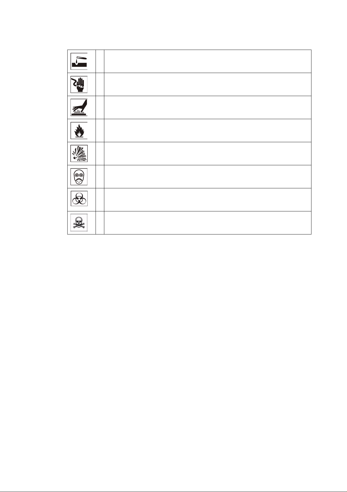
Additional Symbols for Safety Information
Wear safety gloves!
Wear safety goggles!
Thermo Scientific 1-11
Safety Notes
Harmful liquids!
Electrical shock!
Hot surfaces!
Fire hazard!
Explosion hazard!
Suffocation hazard!
Biological hazard!
Contamination hazard!
Standards and Directives
The Box Furnaces complies with the following standards and guidelines:
• Current/Approved Agency standards (Underwriters Laboratory/CSA/CE).
1-12 Thermo Scientific

Introduction
2
Figure 1. 1100 °C Box Furnace
Thermo Fisher Scientific BF51800 Series is a family of ultra lightweight,
economical, laboratory box furnaces. The low thermal mass Moldatherm®
insulation/heating element provides fast duty cycles, energy conservation, and
efficient programming. Refer to Table 1. “BF51800 Series Moldatherm Box
Furnaces” for specifications.
Features and Benefits
• Controlled heat-up rate eliminates thermal shock to materials.
• Quick heat-up and cool-down rates.
• Four chamber sizes.
Thermo Scientific 2-1

Introduction
Specifications
• Energy efficient Moldatherm insulation suitable for high interior-exterior
temperature differential. The unit is rated for a maximum operating
temperature of 1100 °C.
• Resists attack from most corrosive agents and can be used in atmospheres
other than air.
• Side-hinge door for convenient operation.
• Air vent, standard.
• Atmosphere inlet port standard.
• 16 segment programmable temperature controller.
• Digital instrumentation for precise temperature setpoint and display.
Microprocessor capable of automatically optimizes control parameters during
furnace operation.
• Main power ON/OFF switch on control panel.
• Safety interlock switch automatically interrupts power to heating element when
door is opened. This feature protects heating element and eliminates
operator's exposure to electrical shock.
• Type K thermocouple.
Specifications
Table 1. BF51800 Series Moldatherm Box Furnaces.
Model Dimension W X F-B X H in.(cm) Watts Control Type Cord
Chamber Exterior
BF51848A 4X8X4
(1.01X20.3X10.1)
BF51848C
BF51866A 6X9X6
(15.2X22.8X15.2)
BF51866C
15x20x17.5
(38.1x50.8x44.4)
17X21X21.5
(43.1X53.3X54.6)
1,800 16 Segment
Pro grammable Controller
No.
5-20 120/VAC
6-15 208/240
5-20 120/VAC
Voltage Net
Prod.
Wt. lbs
(kg)
45
50/60 Hz
VAC 50/60
Hz
50/60 Hz
(20.4)
65
(29.5)
BF51894C 9X14X9
(22.8X35.6X22.8)
BF51828C 12X18X12
(30.5X45.7X30.5)
2-2 Thermo Scientific
21X25.75X26
(53.3X65.4X66)
24X30X28
(60.1X76.2X71.1)
3,500 6-15 208/240
6-20
5,600 No
Cord
VAC
50/60 Hz
97
(44.0)
142
(64.4)

Pre-Installation
Unpacking
Carefully unpack and inspect the unit and all accessories for damage, if you find
any damage, keep the packing materials and immediately report the damage to
the carrier. We will assist you with your claim, if requested. Do not return goods to
Thermo Fisher Scientific without written authorization. When submitting a claim for
shipping damage, request that the carrier inspect the shipping container and
equipment.
3
Operating Conditions
Sulfates, chlorides, fluorides, alkalis, and V2O5 can have corrosive effects on the
ceramic fiber. Cont act Thermo Fisher Scientific for additional information about the
effects of specific atmospheres on furnace performance.
With prolonged use, hairline cracks can develop in the insulation materials. These
minor cracks will not affect the furnace's performance. We recommend turning off
the furnace completely when not in use. The heating unit is not damaged by rapid
heating and cooling cycles.
Atmosphere Systems
The BF51800 Series furnaces are not designed for use with combustible or inert
atmospheres requiring an air tight chamber . If an exhaust port is used, the furnace
should not be located in an enclosed area without proper ventilation.
Do not use combustible gases in this furnace.
Thermo Scientific 3-1

Pre-Installation
Atmosphere Systems
Avoid combustible products which generate toxic or hazardous
vapor or fumes. Work should only be done in a properly vented
environment.
3-2 Thermo Scientific
Installation
Do not exceed the electrical and temperature ratings printed on the dataplate of
the furnace.
4
Improper operation of the furnace could result in dangerous
conditions. To preclude hazard and minimize risk, follow all
instructions and operate within design limits noted on the
dataplate.
Location
Wiring
Install the furnace in a level area free from vibration. To permit proper air flow,
leave at least three inches of space on all sides of the unit and 12 inches above
the unit.
For detailed wiring information, refer Figure 14. “wiring diagrams” Section
“Wiring Diagrams”.
120 VAC Operation
The BF51848A and BF51866A models operate on 120 VAC, 50/60 Hz, single
phase. Each furnace includes a 120 VAC grounded plug and cord set. The units
are completely prewired and ready for operation.
Before initial start up, inspect the furnace's wiring connections:
1. Remove the corner screws on the back panel of the furnace and detach the
back panel.
2. Check that the thermocouple is securely mounted and undamaged.
Thermo Scientific 4-1
Installation
Wiring
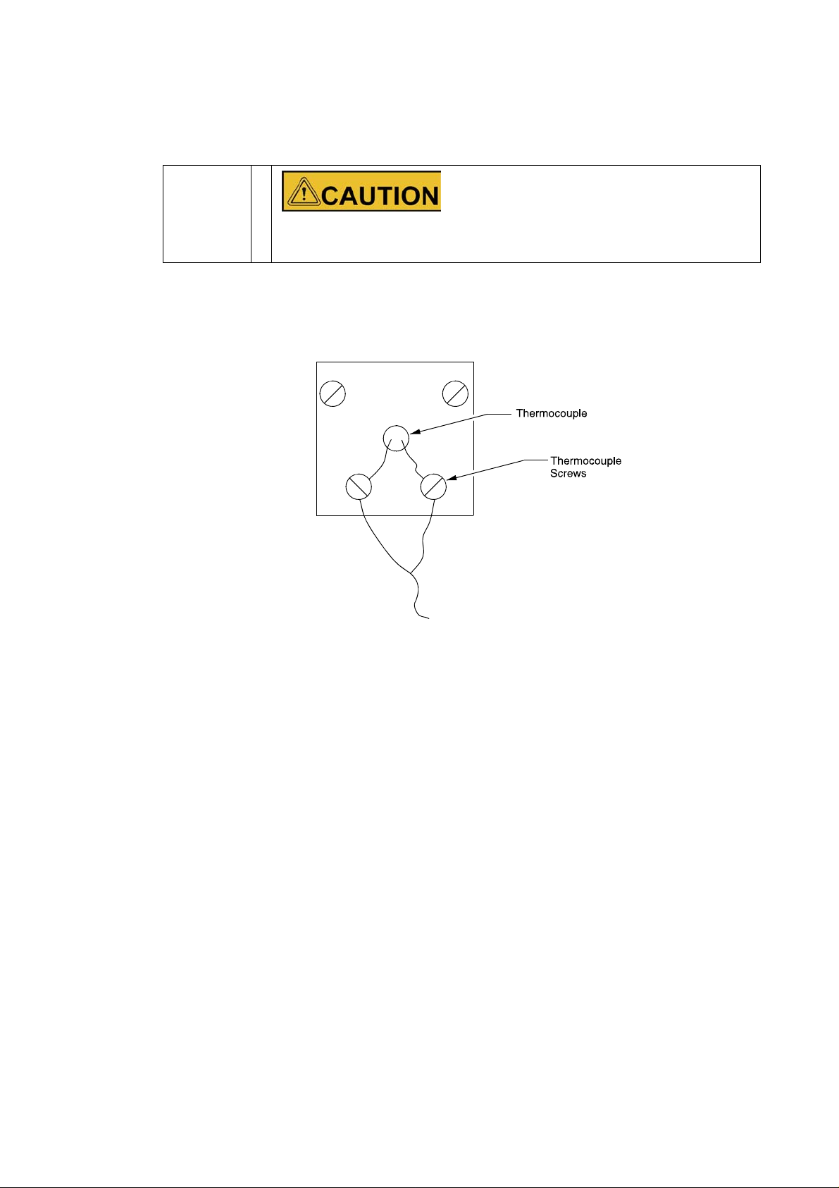
3. Check the thermocouple wiring connections. Refer to Figure 2.
“Thermocouple”. Red is always negative.
Failure to check thermocouple wiring connections before Initial
start up could result in damage to the furnace.
4. Check that all electrical connections are secure. Visually check that the door
properly activates the power interrupt switch near the front of the furnace.
Figure 2. Thermocouple
5. Replace the back panel on the furnace and secure with the corner screws.
6. Plug the line cord into a 120 VAC, 20 amp, grounded line. The furnace draws
approximately 15 amps (1800 W) for models BF51848 and BF51866.
BF51848C, BF51866C, BF51894C and BF51828C
The BF51848C, BF51866C, BF51894C and BF51828C models are 240 VAC
furnaces.
Follow the procedure in Section “BF51848C, BF51866C, and BF51894C
Models” for BF51848C, BF51866C, and BF51894C models and the procedure in
Section “BF51828C” for BF51828C models.
BF51848C, BF51866C, and BF51894C Models
The BF51848C, BF51866C, and BF51894C models include a 240 VAC grounded
plug and cord set. The units are completely prewired and ready for operation.
Before initial start up, inspect the furnace's wiring connections:
4-2 Thermo Scientific

Installation
Wiring
1. Remove the corner screws on the back panel of the furnace and detach the
back panel.
2. Check that the thermocouple is securely mounted and undamaged.
3. Check the thermocouple wiring connections. Refer to Figure 2.
“Thermocouple”. Red is always negative.
Failure to check thermocouple wiring connections before initial
start up could result in damage to the furnace.
4. Check that all electrical connections are secure. Visually check that the door
properly activates the power interrupt switch near the front of the furnace.
5. Replace the back panel on the furnace and secure with the corner screws.
6. Plug the line cord into a 240 VAC, 15 or 20 amp, grounded line, as appropriate
for the supplied line cord.
BF51828C Models
The BF51828C 240 VAC furnaces do not include a 240 VAC grounded plug and
cord set.
Furnace installation requires two power wires and one ground wire (not provided).
The required power wire size is 10 GA, 23.3 amps @ 240V.
To connect the furnace to the power source, complete the following steps:
1. Determine the length of wire needed to connect the furnace to the power
source.
2. Label the power wires Line 1 and Line 2 and label the ground wire Ground.
3. Remove the two cover screws and the cover.
4. Make a 7/8 inch knockout in the cover.Use appropriate covers and fittings for
installation.
5. Thread the Line 1, Line 2, and Ground wires through the 7/8 inch hole. Use
appropriate conduit and clamps for the service wire. Use wire nuts to connect
the wires to the appropriate lead wires:
Wire Label
Line 1 L1
Line 2 L2
Ground GND
Thermo Scientific 4-3

Installation
Exhaust Vent
6. Check that the thermocouple is securely mounted and undamaged. Check the
thermocouple wiring connections. Refer to Figure 2. “Thermocouple”. Red is
always negative.
Failure to check thermocouple wiring connections before initial
start up could result in damage to the furnace.
7. Check that all electrical connections are secure. Visually check that the door
properly activates the power interrupt switch near the front of the furnace.
8. Place the back panel on the furnace and secure with the corner screws.
208 VAC Operation
Thermo Fisher Scientific Moldatherm box furnace heating elements are
specifically designed for operation on 120, 208, or 240 VAC. A furnace wired for
240 VAC operation can also operate on 208 VAC. However, heatup and recovery
times will be longer.
Exhaust Vent
Flow from the exhaust vent on the top of the unit can be adjusted by inserting or
removing the plug provided.
For most applications, the exhaust vent should be fully plugged during operation
of the furnace; a closed vent results in more efficient operation and greater
temperature stability. However, there are some applications which benefit from a
partially or fully open exhaust vent.
The exhaust vent should be partially or fully open for the following applications:
• To provide slow cool down of work load. Some work loads may be damaged by
heat shock when the furnace door is opened. The vent can be opened to allow
work load to cool gradually.
• To remove unwanted vapors and gases from the furnace chamber. If you need
to ventilate vapors and gases outside of the room, be sure to read Section
“Exhaust Port Connection” Chapter “Installation”.
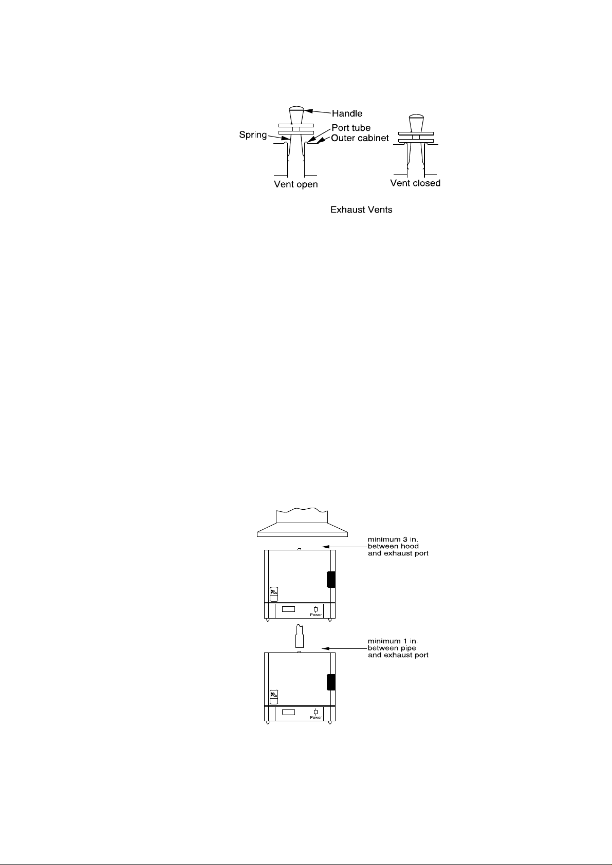
Figure 3. “Exhaust Vents” shows how you can use the plug to adjust flow from
the exhaust vent.
4-4 Thermo Scientific
Exhaust Port Connections
The one inch diameter exhaust port through the top wall of the furnace allows for
the removal of unwanted vapors and gases produced during high-temperature
operation.
Figure 3. Exhaust Vents
Installation
Exhaust Port Connections
When you need to ventilate vapors and gases outside of the room, be sure to
make a proper connection to the exhaust port that allows some room air to flow
into the exhaust. This is necessary to prevent “chimney effect” which sucks heat
out of the chamber and results in slow run-up time or poor temperature uniformity.
Two methods of making the exhaust port connection are shown in Figure 4.
“Preventing Chimney Effect” below . With a hood suspended above the furnace,
be sure that there is at least three inches between the hood and the exhaust port.
If you use a metal tube or pipe leave at least one inch clearance.
Figure 4. Preventing Chimney Effect
Thermo Scientific 4-5

Installation
Atmosphere Inlet
Atmosphere Inlet
BF51800 series furnaces have a factory-installed air/atmosphere inlet.
Most inert atmospheres (i.e. nitrogen, argon, and helium) can be safely run in this
box furnace. However, maximum temperatures may be derated depending on
atmosphere. An initial burn-in period in air is recommended.
Please contact Thermo Fisher Scientific prior to using the furnace with an inert
atmosphere.
The furnace should be run for 7-10 hours at 1100 °C before using an inert
atmosphere and after every 60 hours of use with an inert atmosphere. This burn in
process will help remove contaminants and provides a protective oxide layer on
the heating elements.
This furnace is not designed to be a gas-tight atmosphere furnace.
Atmosphere Inlet Port (Refer to Figure 5. Gas Inlet Tub
Assembly)
The atmosphere inlet tube assembly has been packaged separately to avoid
breakage during shipping and handling.
Even if you do not intend to use the gas inlet, you must install the assembly before
operating the furnace. The only tool you need is a Phillips head screwdriver.
To install the gas inlet assembly:
1. Carefully remove the assembly from the package and inspect for any damage.
2. Remove the two mounting screws from the rear housing panel of the furnace.
3. Insert the ceramic tube end through the access hole in the rear of the furnace
and guide the tube into the back of the chamber.
4. Align the mounting holes in the rear housing panel with the holes in the gas
inlet tube assembly and secure the assembly with the mounting screws.
Figure 5. Gas Inlet Tube Assembly
4-6 Thermo Scientific
Hearth Plate Information
Why Use
• To provide a load bearing surface and distribute the weight of product being
heated.
• To protect the furnace chamber from spillage.
• To lengthen the life of furnace, by allowing heat from the chamber floor to
circulate into the chamber center.
When to use
• Hearth Plates are recommended during each furnace operation.
How to Install
Installation
Hearth Plate Information
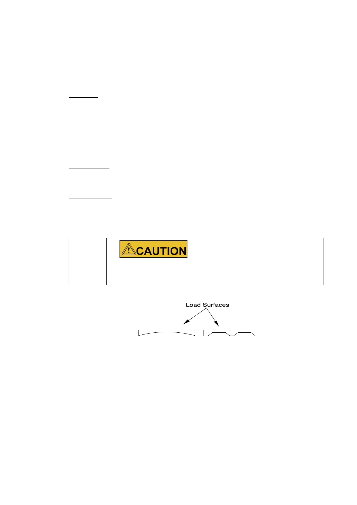
• Hearth plates are designed with one grooved or concave surface.
• The grooved or concave surface must be positioned agained the chamber
floor.
Most hearth plate materials made of ceramic fiber and can be
broken if dropped.
Figure 6. Hearth Plate Concave and Grooved.
Thermo Scientific 4-7
 Loading...