

Page 1

thermo
scientific
Vanquish
Variable Wavelength
Detectors
VC-D40, VF-D40
Operating Manual
4820.7701-EN Revision 2.0 • December 2019
Page 2

Copyright © 2019 Thermo Fisher Scientific Inc. All rights reserved.
Original Operating Manual
The hardware descriptions in this manual revision refer to devices VC-D40-A, VF-D40-A.
Trademarks
Acrobat, Adobe, and Adobe Reader are trademarks of Adobe Systems Incorporated.
Microsoft and Windows are trademarks of Microsoft Corporation.
MP35N is a trademark of SPS Technologies.
Torx is a trademark of Acument Intellectual Properties, LLC.
All other trademarks are property of Thermo Fisher Scientific and its subsidiaries.
Disclaimer
Thermo Fisher Scientific Inc. provides this document to its customers with a product purchase to
use in the product operation. The document is copyright protected; any reproduction of the
whole or any part of this document is strictly prohibited, except with the written authorization
of Thermo Fisher Scientific Inc.
This manual is provided "as is." The contents of this manual are subject to being changed,
without notice, in future revisions.
Thermo Fisher Scientific Inc. makes no representations that this document is complete,
accurate, or error-free. Thermo Fisher Scientific Inc. assumes no responsibility and will not be
liable for any errors, omissions, damage, or loss that might result from any use of this document,
even if the information in the document is followed properly.
This document is not part of any sales contract between Thermo Fisher Scientific Inc. and a
purchaser. This document shall in no way govern or modify any Terms and Conditions of Sale.
The Terms and Conditions of Sale shall govern all conflicting information between the two
documents.
Printed manual version only
Printed in Germany on 100% chlorine-free bleached, high-white paper that is produced in an
environmentally friendly process, leading to a paper profile of zero CO2 emissions.
Manufacturer's address
Dionex Softron GmbH, Part of Thermo Fisher Scientific, Dornierstrasse 4, D-82110 Germering
Page 3

Contacting Us
Ordering Information
Technical Assistance
Contacting Us
There are several ways to contact us:
For ordering information or sales support for HPLC products, contact
your local Thermo Fisher Scientific sales organization. For contact
information, go to Contact Us on http://www.thermofisher.com.
For technical support for HPLC products, contact your local Thermo
Fisher Scientific support organization. For contact information, go to
Contact Us on http://www.thermofisher.com.
Variable Wavelength Detectors (VC-D40, VF-D40)
Operating Manual
Page 3
Page 4

Contacting Us
Page 4 Variable Wavelength Detectors (VC-D40, VF-D40)
Operating Manual
Page 5

Contents
1 Using this Manual ...................................................................... 11
2 Safety......................................................................................... 17
Contents
1.1 About this Manual ................................................................................................12
1.2 Conventions..........................................................................................................13
1.2.1 Safety Messages....................................................................................... 13
1.2.2 Special Notices and Informational Notes ................................................. 13
1.2.3 Typographical Conventions ...................................................................... 14
1.3 Reference Documentation ...................................................................................15
2.1 Safety Symbols and Signal Words.........................................................................18
2.1.1 Safety Symbols and Signal Words in This Manual .................................... 18
2.1.2 Observing this Manual ............................................................................. 18
2.1.3 Safety Symbols on the Device .................................................................. 19
2.1.4 Rating Plate .............................................................................................. 19
2.2 Intended Use ........................................................................................................20
2.3 Safety Precautions................................................................................................21
2.3.1 General Safety Information......................................................................21
2.3.2 Qualification of the Personnel ................................................................. 21
2.3.3 Personal Protective Equipment................................................................ 22
2.3.4 Electrical Safety Precautions .................................................................... 23
2.3.5 General Residual Hazards......................................................................... 23
2.3.6 In Case of Emergency ............................................................................... 26
2.4 Solvent and Additive Information ........................................................................27
2.4.1 General Compatibility .............................................................................. 27
2.4.2 Allowed pH Ranges................................................................................... 28
2.4.3 Allowed Concentrations ........................................................................... 28
2.4.4 Further Information ................................................................................. 29
2.5 Compliance Information.......................................................................................30
3 Device Overview ........................................................................ 31
3.1 Detector Features.................................................................................................32
3.2 Operating Principle...............................................................................................33
3.3 Interior Components ............................................................................................35
3.4 Flow Cell ...............................................................................................................36
3.5 Lamps ...................................................................................................................38
Variable Wavelength Detectors (VC-D40, VF-D40)
Operating Manual
Page 5
Page 6

Contents
3.6 Leak Detection......................................................................................................39
3.7 Operation .............................................................................................................40
4 Unpacking .................................................................................. 41
4.1 Unpacking.............................................................................................................42
4.2 Scope of Delivery..................................................................................................44
5 Installation................................................................................. 45
5.1 Safety Guidelines for Installation .........................................................................46
5.2 Installing the Device .............................................................................................47
5.3 Site Requirements ................................................................................................49
5.3.1 Power Considerations .............................................................................. 49
5.3.2 Power Cord............................................................................................... 49
5.3.3 Condensation ........................................................................................... 50
5.4 Accessing the Interior Components .....................................................................51
5.5 Setting Up the Hardware......................................................................................52
5.5.1 System Arrangement................................................................................ 52
5.5.2 Connecting the Device ............................................................................. 53
5.5.3 Connecting the Power Cord ..................................................................... 55
5.6 Installing a VIS Lamp (Tungsten Lamp) (Optional)................................................56
5.7 Installing a Flow Cell .............................................................................................59
5.7.1 Removing the Diagnostic Cell................................................................... 59
5.7.2 Installing a Flow Cell without Connection Unit ........................................ 60
5.7.3 Installing a Flow Cell with Connection Unit.............................................. 60
5.8 Setting Up the Flow Connections .........................................................................62
5.8.1 General Information and Guidelines........................................................ 62
5.8.2 Guiding Capillaries and Tubing Through the System................................ 63
5.8.3 Installing the Partition Panel Plugs........................................................... 65
5.8.4 Connecting Fittings, Capillaries, and Tubing ............................................ 66
5.8.5 Flow Connections to the Flow Cell ........................................................... 68
5.8.6 Guiding Liquid Leaks to Waste ................................................................. 72
5.9 Turning On the Device..........................................................................................73
5.10 Setting Up the Device in the Software .................................................................74
6 Operation................................................................................... 75
6.1 Introduction to this Chapter.................................................................................76
6.2 Safety Guidelines for Operation ...........................................................................77
Page 6 Variable Wavelength Detectors (VC-D40, VF-D40)
Operating Manual
Page 7

Contents
6.3 Control Elements..................................................................................................78
6.3.1 Keypad...................................................................................................... 78
6.3.2 Status Indicators....................................................................................... 79
6.4 Power On/Off Control ..........................................................................................81
6.5 Preparing the Device for Operation .....................................................................82
6.5.1 Guidelines for Use of Flow Cells ............................................................... 84
6.5.2 Turning On the Lamps .............................................................................. 85
6.6 Operational Modes of the Device.........................................................................86
6.6.1 Single-Channel Mode ............................................................................... 86
6.6.2 Multi-Channel Mode ................................................................................86
6.7 Important Operating Parameters.........................................................................88
6.8 Optimizing the Performance of the Device ..........................................................90
6.8.1 General Guidelines ................................................................................... 90
6.8.2 Overview of Optimization Parameters..................................................... 91
6.8.3 Wavelength .............................................................................................. 91
6.8.4 Data Collection Rate................................................................................. 92
6.8.5 Response Time and Peak Width............................................................... 92
6.8.6 Baseline Behavior..................................................................................... 93
6.9 Shutting Down the Device ....................................................................................94
6.9.1 Short-Term Shutdown (Interruption of Operation) ................................. 94
6.9.2 Long-Term Shutdown............................................................................... 95
7 Maintenance and Service ........................................................... 99
7.1 Introduction to Maintenance and Service......................................................... 100
7.2 Safety Guidelines for Maintenance and Service................................................ 101
7.3 General Rules for Maintenance and Service ..................................................... 103
7.4 Routine and Preventive Maintenance............................................................... 104
7.4.1 Maintenance Plan .................................................................................. 104
7.4.2 Cleaning or Decontaminating the Device............................................... 104
7.4.3 Predictive Performance.......................................................................... 106
7.5 Lamps ................................................................................................................ 107
7.5.1 Replacing the UV Lamp (Deuterium Lamp) ............................................ 107
7.5.2 Replacing the VIS Lamp (Tungsten Lamp) ..............................................110
7.6 Flow Cell ............................................................................................................ 114
7.6.1 Guidelines for Handling Flow Cells......................................................... 115
7.6.2 Cleaning the Flow Cell ............................................................................ 115
7.6.3 Removing the Flow Cell.......................................................................... 116
7.6.4 Installing a Diagnostic Cell...................................................................... 118
Variable Wavelength Detectors (VC-D40, VF-D40)
Operating Manual
Page 7
Page 8

Contents
7.7 Performing a Wavelength Validation and Calibration....................................... 119
7.8 Replacing the Waste Line .................................................................................. 121
7.9 Replacing the Main Power Fuses....................................................................... 122
7.10 Updating the Device Firmware.......................................................................... 124
7.11 Replacing the Doors........................................................................................... 126
7.12 Transporting or Shipping the Device ................................................................. 128
7.12.1 Preparing the Device for Transport........................................................ 128
7.12.2 Transporting the Device to a New Location ........................................... 129
7.12.3 Shipping the Device................................................................................ 130
7.13 Replacing the Slide-In Module........................................................................... 131
7.13.1 Removing the Slide-In Module ............................................................... 131
7.13.2 Returning the Slide-In Module ...............................................................132
7.13.3 Installing the Slide-In Module ................................................................ 133
7.13.4 Setting Up the Slide-In Module ..............................................................135
8 Troubleshooting....................................................................... 137
8.1 General Information about Troubleshooting .................................................... 138
8.2 Messages ........................................................................................................... 140
8.3 Checking the Flow Cell....................................................................................... 145
8.4 Resolving Liquid Leaks ....................................................................................... 146
9 Specifications ........................................................................... 149
9.1 Performance Specifications............................................................................... 150
9.1.1 Detector ................................................................................................. 150
9.1.2 Flow Cells................................................................................................ 152
9.2 Physical Specifications....................................................................................... 153
10 Accessories, Consumables and Replacement Parts ................... 155
10.1 General Information.......................................................................................... 156
10.2 Ship Kit............................................................................................................... 157
10.3 Optional Accessories ......................................................................................... 158
10.4 Consumables and Replacement Parts ............................................................... 159
11 Appendix.................................................................................. 161
11.1 Compliance Information.................................................................................... 162
11.1.1 Declarations of Conformity ....................................................................162
11.1.2 WEEE Compliance .................................................................................. 163
Page 8 Variable Wavelength Detectors (VC-D40, VF-D40)
Operating Manual
Page 9

Contents
11.1.3 FCC Compliance...................................................................................... 163
11.1.4 NIST Compliance .................................................................................... 163
11.1.5 Manual Release History.......................................................................... 163
11.2 UV Cutoff Wavelengths of Solvents................................................................... 165
11.3 Digital I/O .......................................................................................................... 166
Index........................................................................................ 169
Variable Wavelength Detectors (VC-D40, VF-D40)
Operating Manual
Page 9
Page 10

Contents
Page 10 Variable Wavelength Detectors (VC-D40, VF-D40)
Operating Manual
Page 11

1 • Using this Manual
1 Using this Manual
This chapter provides information about this manual, the conventions
used throughout the manual, and the reference documentation that is
available in addition to this manual.
Variable Wavelength Detectors (VC-D40, VF-D40)
Operating Manual
Page 11
Page 12

1 • Using this Manual
1.1 About this Manual
This manual describes the functional features and operating principle of
your Vanquish™ device and provides instructions for installation, set up,
start up, shut down, operation, maintenance and troubleshooting.
The layout of this manual is designed to provide quick reference to the
sections of interest to the user. To obtain a full understanding of your
device, read this manual thoroughly.
This manual also contains safety messages, precautionary statements,
and special notices that can prevent personal injury, damage to the
device, or loss of data when followed properly.
Note the following:
• The device configuration may vary; therefore, not all descriptions
necessarily apply to your particular device.
• If some detail applies to only one model or variant, the model or
variant is identified by name.
• Illustrations in this manual are provided for basic understanding.
They can vary from the actual model of the device or component.
However, this does not influence the descriptions. No claims can be
derived from the illustrations in this manual.
The descriptions in this manual assume that the device is installed in the
Vanquish system stack. If this is not the case, additional hardware is
required and must be ordered separately. The information in this
manual applies correspondingly.
Page 12 Variable Wavelength Detectors (VC-D40, VF-D40)
Operating Manual
Page 13

1.2 Conventions
This section describes the conventions that are used throughout this
manual.
1.2.1 Safety Messages
The safety messages and precautionary statements in this manual
appear as follows:
• Safety messages or precautionary statements that apply to the
• Safety messages or precautionary statements that apply to an entire
1 • Using this Manual
entire manual and all procedures in this manual are grouped in the
Safety chapter.
section or to multiple procedures in a section appear at the
beginning of the section to which they apply.
• Safety messages that apply to only a particular section or procedure
appear in the section or procedure to which they apply. They appear
different from the main flow of text.
Safety messages are often preceded by an alert symbol and/or alert
word. The alert word appears in uppercase letters and in bold type.
Make sure that you understand and follow all safety messages
presented in this manual.
1.2.2 Special Notices and Informational Notes
Special notices and informational notes in this manual appear different
from the main flow of text. They appear in boxes and a note label
identifies them. The label text appears in uppercase letters and in bold
type.
NOTICE
Highlights information necessary to prevent damage to the device or
invalid test results.
TIP Highlights information of general interest or helpful information that
can make a task easier or optimize the performance of the device.
Variable Wavelength Detectors (VC-D40, VF-D40)
Operating Manual
Page 13
Page 14

1 • Using this Manual
1.2.3 Typographical Conventions
These typographical conventions apply to the descriptions in this
manual:
Data Input and Output
• The following appears in bold type:
¨ Input that you enter by the keyboard or that you select with the
mouse
¨ Buttons that you click on the screen
¨ Commands that you enter by the keyboard
¨ Names of, for example, dialog boxes, properties, and parameters
• For brevity, long expressions and paths appear in the condensed
form, for example: Click Start > All Programs > Thermo
Chromeleon7 > Services Manager > Start Instrument Controller.
References and Messages
• References to additional documentation appear italicized.
• Messages that appear on the screen are identified by quotation
marks.
Viewpoint
If not otherwise stated, the expressions left and right in this manual
always refer to the viewpoint of a person that is facing the device from
the front.
Particularly Important Words
Particularly important words in the main flow of text appear italicized.
Electronic Manual Version (PDF)
The electronic version (PDF) of the manual contains numerous links that
you can click to go to other locations within the manual. These include:
• Table of contents entries
• Index entries
• Cross-references (in blue text), for example, to sections and figures
Page 14 Variable Wavelength Detectors (VC-D40, VF-D40)
Operating Manual
Page 15

1.3 Reference Documentation
In addition to this operating manual, other documentation is available
for reference.
Hardware Documentation
Additional hardware documentation includes the following:
• Operating manuals for the other modules of the Vanquish system
A printed version of the manual is shipped with the device.
• Vanquish System Operating Manual
A printed version of the manual is shipped with the Vanquish system
base and solvent rack.
• Instrument Installation Qualification Operating Instructions
TIP Electronic versions of these manuals are available as PDF (Portable
Document Format) files. To open and read the PDF files, Adobe™
Reader™ or Adobe™ Acrobat™ is required.
1 • Using this Manual
Software Documentation
Additional software documentation includes the following:
• Chromeleon™ Help and documents
In addition, the following documentation is available (availability
depends on the software version):
• Installation Guide
• Instrument Configuration Manager Help
• Quick Start Guide
The Chromeleon Help provides extensive information and
comprehensive reference material for all aspects of the software.
For basic information about device installation and configuration,
refer to the Installation Guide.
For specific information about a certain device, refer to the
Instrument Configuration Manager Help. In Chromeleon7, devices
are called modules.
For information about the main elements of the user interface and
step-by-step guidance through the most important workflows, refer
to the Quick Start Guide.
• Reference Card
For a concise overview of the most important workflows, refer to
the Reference Card.
Variable Wavelength Detectors (VC-D40, VF-D40)
Operating Manual
Page 15
Page 16

1 • Using this Manual
Third-Party Documentation
TIP The Chromeleon Help and documents are included in the software
shipment.
Refer also to the user documentation provided by the manufacturers of
third-party components and materials, for example, Safety Data Sheets
(SDSs).
Page 16 Variable Wavelength Detectors (VC-D40, VF-D40)
Operating Manual
Page 17

2 • Safety
2 Safety
This chapter provides general and specific safety information and
informs about the intended use of the device.
Variable Wavelength Detectors (VC-D40, VF-D40)
Operating Manual
Page 17
Page 18
2 • Safety
2.1 Safety Symbols and Signal Words
2.1.1 Safety Symbols and Signal Words in This Manual
This manual contains safety messages to prevent injury of the persons
using the device.
The safety symbols and signal words in this manual include the
following:
Always be aware of the safety information. Do not proceed until you
have fully understood the information and consider the consequences of
what you are doing.
CAUTION
Indicates a hazardous situation that, if not avoided, could result in minor
or moderate injury.
WARNING
Indicates a hazardous situation that, if not avoided, could result in
serious injury.
2.1.2 Observing this Manual
Observe the following:
• Before installing or operating the device, read this manual carefully
to be familiar with the device and this manual. The manual contains
important information with regard to user safety as well as use and
care of the device.
• Always keep the manual near the device for quick reference.
• Save this manual and pass it on to any subsequent user.
Read, understand, and comply with all safety messages and
precautionary statements presented in this manual.
Page 18 Variable Wavelength Detectors (VC-D40, VF-D40)
Operating Manual
Page 19
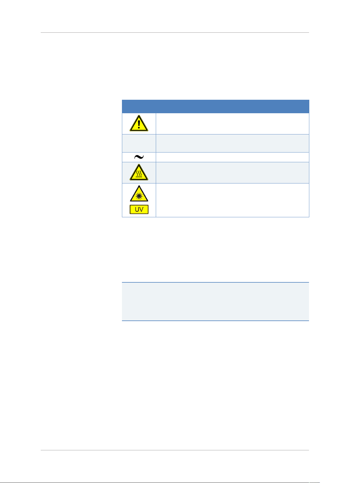
2.1.3 Safety Symbols on the Device
The table lists the safety symbols that appear on the device or on labels
affixed to the device. Follow the safety notices in this manual to prevent
the risk of operator injury or damage to the device.
Symbol Description
Indicates a potential hazard. Refer to this manual to avoid the risk of
personal injury and/or to prevent damage to the device.
2 • Safety
2.1.4 Rating Plate
—
Ο
Power supply is on
Power supply is off
Indicates alternating current.
Indicates that the surface becomes hot during operation. Do not
touch these surfaces while they are heated up.
Indicates that the UV radiation produced by the deuterium lamp in
the device may be harmful to eyes and skin. Do not look directly into
the light produced by the deuterium lamp. Never operate the lamp
outside the device.
The rating plate is present on the device near the electrical connections.
The rating plate indicates the serial number, part number, module
name, revision number (if any), line and fuse rating, and the
manufacturer's address.
TIP An additional type label on the leak tray of the device indicates the
module name, serial number, part number, and revision number (if any).
To facilitate device identification, have the information from this label
available when communicating with Thermo Fisher Scientific.
Variable Wavelength Detectors (VC-D40, VF-D40)
Operating Manual
Page 19
Page 20

2 • Safety
2.2 Intended Use
The device is intended to be part of the Vanquish system.
The intended use of the Vanquish system is to analyze mixtures of
compounds in sample solutions.
The device is for use by qualified personnel and in laboratory
environment only.
The device and Vanquish system are intended to be used as General
Laboratory Equipment (GLE).
They are not intended for use in diagnostic procedures.
Laboratory Practice
Thermo Fisher Scientific recommends that the laboratory in which the
Vanquish system is used follow best practices for LC analyses. This
includes among others:
• Using appropriate standards
• Regularly running calibration
• Establishing shelf life limits and following them for all consumables
used with the system
• Running the system according to the laboratory's verified and
validated 'lab developed test' protocol
Page 20 Variable Wavelength Detectors (VC-D40, VF-D40)
Operating Manual
Page 21

2.3 Safety Precautions
2.3.1 General Safety Information
All users must observe the general safety information presented in this
section and all specific safety messages and precautionary statements
elsewhere in this manual during all phases of installation, operation,
troubleshooting, maintenance, shutdown, and transport of the device.
If the device is used in a manner not specified by Thermo Fisher
Scientific, the protection provided by the device could be impaired.
Observe the following:
• Operate the device only within its technical specifications.
• Use only the replacement parts and additional components, options,
and peripherals specifically authorized and qualified for the device
by Thermo Fisher Scientific.
2 • Safety
• Perform only the procedures that are described in this operating
manual and in supporting documents for the device. Follow all
instructions step by step and use the tools recommended for the
procedure.
• Open the enclosure of the device and other components only if
specifically instructed to do so in this manual.
• Thermo Fisher Scientific cannot be held liable for any damage,
material or otherwise, resulting from inappropriate or improper use
of the device. If there is any question regarding appropriate usage,
contact Thermo Fisher Scientific before proceeding.
Safety Standard
This device is a Safety Class I instrument (provided with terminal for
protective grounding). The device has been manufactured and tested
according to international safety standards.
2.3.2 Qualification of the Personnel
Observe the information below on the proper qualification of the
personnel installing and/or operating the device.
Variable Wavelength Detectors (VC-D40, VF-D40)
Operating Manual
Page 21
Page 22

2 • Safety
Installation
Only skilled personnel are permitted to install the device and to
establish the electrical connections according to the appropriate
regulations.
• Thermo Fisher Scientific recommends always having service
personnel certified by Thermo Fisher Scientific perform the
installation (for brevity, referred to as Thermo Fisher Scientific
service engineer).
• If a person other than a Thermo Fisher Scientific service engineer
installs and sets up the module, the installer is responsible for
ensuring the safety of the module and system.
General Operation
The device is designed to be operated only by trained and qualified
personnel in a laboratory environment.
All users must know the hazards presented by the device and the
substances they are using. All users should observe the related Safety
Data Sheets (SDSs).
2.3.3 Personal Protective Equipment
Wear personal protective equipment and follow good laboratory
practice to protect you from hazardous substances. The appropriate
equipment depends on the hazard. For advice on the hazards and the
equipment required for the substances you are using, refer to the
material handling and safety data sheet provided by the vendor.
An eyewash facility and a sink should be available nearby. If any
substance contacts your skin or eyes, wash the affected area and seek
medical attention.
Protective Clothing
To protect you from chemical splashes, harmful liquids, or other
contamination, put on appropriate protective clothing, such as a lab
coat.
Protective Eyewear
To prevent liquids from striking your eyes, put on appropriate protective
eyewear, such as safety glasses with side shields. If there is a risk of
splashing liquids, put on goggles.
Page 22 Variable Wavelength Detectors (VC-D40, VF-D40)
Operating Manual
Page 23

Gloves
To protect you from harmful liquids and avoid personal injury during
maintenance or service, put on appropriate protective gloves.
2.3.4 Electrical Safety Precautions
WARNING—Electric Shock or Damage to the Device
High voltages are present inside the device that could cause an electric
shock or damage to the device.
• Do not make any changes to the electrical or grounding connections.
• If you suspect any kind of electrical damage, disconnect the power
cord and contact Thermo Fisher Scientific Technical Support for
assistance.
• Do not open the housing or remove protective panels unless
specifically instructed to do so in this manual.
2 • Safety
• Do not place liquid reservoirs directly upon the device. Liquid might
leak into the device and get into contact with electronic components
causing a short circuit. Instead, place liquid reservoirs in the solvent
rack that is available for the Vanquish system.
2.3.5 General Residual Hazards
Pay attention to the following general residual hazards when working
with the device:
Variable Wavelength Detectors (VC-D40, VF-D40)
Operating Manual
Page 23
Page 24
2 • Safety
WARNING—Hazardous Substances
Solvents, mobile phases, samples, and reagents might contain toxic,
carcinogenic, mutagenic, infectious, or otherwise harmful substances.
The handling of these substances can pose health and safety risks.
• Be sure that you know the properties of all substances that you are
using. Avoid exposure to harmful substances. If you have any doubt
about a substance, handle the substance as if it is potentially
harmful.
• Wear personal protective equipment as required by the hazard and
follow good laboratory practice.
• Reduce the volume of substances to the minimum volume required
for sample analysis.
• Do not operate the device in a potentially flammable environment.
• Avoid accumulation of harmful substances. Make sure that the
installation site is well ventilated.
• Dispose of hazardous waste in an environmentally safe manner that
is consistent with local regulations. Follow a regulated, approved
waste disposal program.
WARNING—Biohazard
Biohazardous material, for example microorganisms, cell cultures,
tissues, body fluids, and other biological agents can transmit infectious
diseases. To avoid infections with these agents:
• Assume that all biological substances are at least potentially
infectious.
• Wear personal protective equipment as required by the hazard and
follow good laboratory practice.
• Dispose of biohazardous waste in an environmentally safe manner
that is consistent with local regulations. Follow a regulated,
approved waste disposal program.
WARNING—Self-Ignition of Solvents
Solvents with a self-ignition temperature below 150°C might ignite
when in contact with a hot surface (for example, due to leakage in the
chromatography system).
Avoid the use of these solvents.
Page 24 Variable Wavelength Detectors (VC-D40, VF-D40)
Operating Manual
Page 25

2 • Safety
WARNING—Hazardous Vapors
Mobile phases and samples might contain volatile or flammable
solvents. The handling of these substances can pose health and safety
risks.
• Avoid accumulation of these substances. Make sure that the
installation site is well ventilated.
• Avoid open flames and sparks.
• Do not operate the device in the presence of flammable gases or
fumes.
CAUTION—Escape of Hazardous Substances from PEEK Capillaries
In the Vanquish system, capillaries made of PEEK may be used. Swelling
or attack by acids can cause PEEK capillaries to start leaking or to burst.
Certain chemicals, for example, trichlormethane (CHCl3), dimethyl
sulfoxide (DMSO), or tetrahydrofuran (THF) can cause PEEK to swell.
Concentrated acids, such as sulfuric acid and nitric acid, or a mixture of
hexane, ethyl acetate, and methanol, can attack PEEK.
• Swelling or attack is not a problem with brief flushing procedures.
• For more information, refer to the technical literature on the
chemical resistance of PEEK.
CAUTION—Allergic Reaction
Some capillaries in the Vanquish system are made of MP35N™, a nickel/
cobalt-based alloy. Individuals with sensitivity to nickel/cobalt may show
an allergic reaction from skin contact.
CAUTION—Sparking due to Electrostatic Discharge
Liquid flowing through capillaries can generate static electricity. This
effect is particularly present with insulating capillaries and nonconductive solvents (for example, pure acetonitrile). Discharge of
electrostatic energy might lead to sparking, which could constitute a fire
hazard.
Prevent the generation of static electricity near the chromatography
system.
Variable Wavelength Detectors (VC-D40, VF-D40)
Operating Manual
Page 25
Page 26

2 • Safety
2.3.6 In Case of Emergency
WARNING—Safety Hazard
In case of emergency, disconnect the device from the power line.
Page 26 Variable Wavelength Detectors (VC-D40, VF-D40)
Operating Manual
Page 27

2.4 Solvent and Additive Information
2.4.1 General Compatibility
To protect optimal functionality of the Vanquish system, observe these
recommendations on the use of solvents and additives:
• The system must be used with reversed-phase (RP) compatible
solvents and additives only.
• Use only solvents and additives that are compatible with all parts in
the flow path.
TIP In a Vanquish Core system, normal-phase (NP) compatible solvents
and additives may be used if the VC-pumps and the VC-autosamplers are
modified with the components from the Normal-Phase (NP) kit. Refer to
the Operating Manuals for the pumps and autosamplers.
2 • Safety
NOTICE
If the system flow path includes a Vanquish charged aerosol detector,
observe the specific solvent and additive information for this detector.
Refer to the Operating Manual for the Vanquish charged aerosol
detector.
Variable Wavelength Detectors (VC-D40, VF-D40)
Operating Manual
Page 27
Page 28

2 • Safety
2.4.2 Allowed pH Ranges
Allowed pH ranges (standard system configuration):
System
(Standard
Configuration)
Vanquish Core 1-13 • pH values of 2 or less: The application time should
Vanquish
Horizon
Vanquish Flex
2.4.3 Allowed Concentrations
Allowed
pH ranges
2-12
Remarks
be as short as possible. Flush the system
thoroughly after these applications.
• pH values higher than 9.5 with optical detectors:
Avoid using mobile phases with a pH value higher
than 9.5 together with optical detectors. This can
impair the functionality and optical performance
of the detector flow cell.
• pH values higher than 12: May affect
electrochemical detection. Before using highly
alkaline solvents for flushing the system,
disconnect the detector from the system.
• Mobile phases containing ammonium hydroxide: In
rare cases, a shortened lifetime of reversed-phase
(UHMW-PE) piston seals has been observed with
high pH, ammonium hydroxide containing mobile
phases and prolonged exposure.
Allowed concentrations (standard system configuration):
System
(Standard
Configuration)
Vanquish Core 0.1 mol/L
Vanquish Horizon
Vanquish Flex
Chloride Buffer Remarks
or less
1 mol/L or
less
1 mol/L or
less
-
• High chloride concentration:
The application time should be
as short as possible. Flush the
system thoroughly after these
applications.
• Mobile phases containing
ammonium hydroxide: In rare
cases, a shortened lifetime of
reversed-phase (UHMW-PE)
piston seals has been observed
with high pH, ammonium
hydroxide containing mobile
phases and prolonged
exposure.
Page 28 Variable Wavelength Detectors (VC-D40, VF-D40)
Operating Manual
Page 29

2.4.4 Further Information
• For details about the materials that are used in the analytical flow
• Follow any specific recommendations presented in other sections of
• Observe the general guidelines and recommendations on the use of
2 • Safety
path of the device, see the Specifications chapter in this manual. For
information about the materials that are used in the flow path of the
other modules in the Vanquish system, refer to the Specifications
chapter in the Operating Manual for the modules.
this manual. Refer also to the operating manuals for all modules in
the Vanquish system. They may provide additional guidelines and
information.
solvents and additives in the chromatography system. Refer to Use
of Solvents and Additives in the Vanquish System Operating Manual.
Variable Wavelength Detectors (VC-D40, VF-D40)
Operating Manual
Page 29
Page 30

2 • Safety
2.5 Compliance Information
Thermo Fisher Scientific performs complete testing and evaluation of its
products to ensure full compliance with applicable domestic and
international regulations. When the device is delivered to you, it meets
all pertinent electromagnetic compatibility (EMC) and safety standards
as described in this manual.
Changes that you make to the device may void compliance with one or
more of these EMC and safety standards. Changes to the device include
replacing a part or adding components, options, or peripherals not
specifically authorized and qualified for the product by Thermo Fisher
Scientific. To ensure continued compliance with EMC and safety
standards, replacement parts and additional components, options, and
peripherals must be ordered from Thermo Fisher Scientific or one of its
authorized representatives.
The device has been shipped from the manufacturing site in a safe
condition.
See also
2 Compliance Information (}page162)
Page 30 Variable Wavelength Detectors (VC-D40, VF-D40)
Operating Manual
Page 31

3 • Device Overview
3 Device Overview
This chapter introduces you to the device and the main components.
Variable Wavelength Detectors (VC-D40, VF-D40)
Operating Manual
Page 31
Page 32

3 • Device Overview
3.1 Detector Features
The detector comprises the following main features:
• The detector is a dual-beam, variable wavelength photometer with
one measurement and one internal reference beam.
• Two different light sources provide a wavelength detection range
from 190 nm to 750nm (VC-D40) and from 190 nm to 900 nm (VFD40):
¨ A deuterium lamp (referred to as UV lamp) for ultraviolet and
visible detection and
¨ A tungsten lamp (referred to as VIS lamp) for visible and near-
infrared detection (optional for VC-D40)
• Internal validation of the wavelength accuracy with holmium oxide
filter
• Multi-Wavelength Operation for additional operation functions,
measuring simultaneously at up to two (VC-D40) or four (VF-D40)
different wavelengths
• Data collection rates of up to 125Hz (VC-D40) and up to 250Hz (VF-
D40) under Chromeleon7.2 software or later, in single-channel
mode
• Spectra measurements
• Two optical filters for eliminating higher order light
To ensure optimal measurement results over the entire wavelength
range, the optical filters automatically move into the light path (also
in multi-wavelength operation).
• Automatic wavelength calibration after power-up and when the
lamp configuration was changed.
• A shutter (motorized filter paddle) to move into the light path before
the flow cell
The shutter can move into the following positions:
¨ Open position for data acquisition
¨ Closed (dark) position for protection of the flow cell and for dark
signal measurements
¨ Holmium oxide filter position for validation of wavelength
accuracy
• Availability of flow cells for different fields of applications (for
details, see Flow Cells (}page152))
Page 32 Variable Wavelength Detectors (VC-D40, VF-D40)
Operating Manual
Page 33

3.2 Operating Principle
The detector is a dual-beam spectrophotometer that is designed for
ultraviolet (UV), visible (VIS) and near-infrared (NIR) absorption
spectrophotometry in combination with HPLC or UHPLC separations.
Photometric detection bases upon the absorption of monochromatic
light. The optical system of the detector provides a deuterium lamp
(UV), and may provide a tungsten lamp (VIS), which is optional for VCD40 detectors. A concave mirror (no.2) focuses the light from the VIS
lamp (no.1) to the aperture of the UV lamp (no.3). Another mirror (no.
4) receives the combined light from both light sources and focuses it into
the entrance slit (no. 6). The shutter (motorized filter paddle, no.5) can
be moved into the light path before the flow cell to protect the flow cell.
The light passes through the entrance slit to the mirror (no.7) and on to
the grating (no. 8), where the light beam is diffracted. The angular
position of the grating determines the selected wavelength that is
focused by the mirror (no.9) and directed to the beamsplitter (no. 10)
and flow cell (no. 13).
3 • Device Overview
The beamsplitter (no.10) directs part of the light beam to the reference
diode (no.11). If the flow cell is removed, a safety shutter (no. 12) blocks
the light beam to protect the user from UV radiation. If a flow cell is
installed, the remaining light travels through the flow cell (no.13), and is
partly absorbed depending on the sample solution in the flow cell. It
travels on to the measurement photodiode (no. 14), where the
remaining light intensity is measured. The absorbance of the analyte is
calculated from the measured intensities based on the law of LambertBeer.
The response of the detector is proportional to the concentration of the
analyte. Simultaneously, the reference beam intensity is measured and
used to compensate any intensity fluctuations of the light source.
The following picture shows the optics of the detector, and illustrates
how the detector operates:
Variable Wavelength Detectors (VC-D40, VF-D40)
Operating Manual
Page 33
Page 34

3 • Device Overview
Figure1: Operating principle of the optics
No. Description
1 VIS lamp (tungsten lamp)
2 Mirror (VIS)
3 UV lamp (deuterium lamp)
4 Mirror (combined light)
5 Shutter
6 Entrance slit
7 Mirror
8 Grating
9 Mirror
10 Beamsplitter
11 Reference photodiode
12 Safety shutter
13 Flow cell
14 Measurement photodiode
Page 34 Variable Wavelength Detectors (VC-D40, VF-D40)
Operating Manual
Page 35

3.3 Interior Components
1
2
3
4 5
6 7
8
9
10
11
The user-accessible components of the device are located directly
behind the front doors:
3 • Device Overview
Figure2: Interior components (here with flow cell with connection unit installed)
No. Description
1 Cooling air intake
2 Keypad with status indicators
3 Screw holes for connection unit (left-side installation)
4 Flow cell with connection unit
5 Connection unit
6 Leak tray
7 Type label, indicating the module name, serial number, part number, and
revision number (if any)
8 Drain port
9 Leak sensor
10 Partition panel
The recesses in the partition panel are used to route capillaries with the help
of special plugs (see Installing the Partition Panel Plugs (}page65)).
11 Lamp house cover
Depending on the detector configuration, a UV lamp or a UV and a VIS lamp
are installed in the lamp house.
Variable Wavelength Detectors (VC-D40, VF-D40)
Page 35
Operating Manual
Page 36

3 • Device Overview
1
1
2
4
6
3
5
3.4 Flow Cell
The detector design allows easy access to the flow cell on the interior
front.
Figure3: Flow cell (example)
No. Description
1 Flow cell screws
2 Flow cell handle
3 Drain outlet
4 Connector for outlet capillary
5 Connection unit screw
6 Connector for inlet capillary
Flow Cell Label
One or more flow cell labels are present on the flow cell, which contain
information such as flow cell type, part number, and serial number.
Flow Cell Identification Chip
An identification (ID) chip on the flow cell stores information, including
the flow cell type and the serial number of the flow cell. The ID chip also
stores data during operation, such as the exposure time to the light.
When the flow cell is installed, the detector reads the data from the chip
and transfers the flow cell data to the Chromeleon software.
Heat exchanger
Standard flow cells and semi-micro flow cells are equipped with a builtin heat exchanger.
Page 36 Variable Wavelength Detectors (VC-D40, VF-D40)
Operating Manual
Page 37

Flow Cell Types
3 • Device Overview
The heat exchanger helps to adapt the temperature of the mobile phase
to the flow cell temperature before the mobile phase enters the optical
flow path within the flow cell. Note that the volume of the heat
exchanger and inlet capillary influences the retention times and peak
widths.
The detector is shipped with a diagnostic cell. Replace the diagnostic cell
with a flow cell that is appropriate for your application. Depending on
the application needs, different types of flow cells are available for the
detector.
For flow cell ordering information, see Optional Accessories
(}page158).
For the flow cell specifications, including, for example, materials in the
flow path and pressure limit, see Flow Cells (}page152).
For details about the flow cells or about the availability of other flow
cells, refer to the Thermo Fisher Scientific sales organization.
See also
2 Guidelines for Use of Flow Cells (}page84)
Variable Wavelength Detectors (VC-D40, VF-D40)
Operating Manual
Page 37
Page 38

3 • Device Overview
3.5 Lamps
Lamp Types
Two different light sources provide the light for a wavelength detection
range from 190nm to 750nm (VC-D40), or from 190nm to900 nm (VFD40). Note that the VIS lamp is optional for VC-D40.
Refer to the table below to find out which lamp is recommended if at
least one of your detection wavelengths is within the range indicated in
the left column.
At least one detection wavelength Recommended lamp(s)
≤345nm UV
Between 346 and 670nm UV and VIS (turn on both lamps)
>670nm VIS
Identification Chip
Each lamp is equipped with an identification (ID) chip. The ID chip stores
information about the lamp, including the number of lamp ignitions, and
the operating time of the lamp, thus providing an overview of the lamp
status.
When a lamp is installed, the ID chip is automatically connected to the
detector electronics.
Page 38 Variable Wavelength Detectors (VC-D40, VF-D40)
Operating Manual
Page 39

3.6 Leak Detection
Leaks are a potential safety issue.
The leak sensor inside the device monitors the device for liquid leaks
from the flow connections. The liquid is collected in the leak tray and
guided to the drain port. From the drain port, the liquid is discharged to
waste through the drain system of the Vanquish system.
When the leak sensor detects leakage, the status indicators change to
red and beeping starts to alert you. Follow the instructions in this
manual to find and eliminate the source for the leakage.
3 • Device Overview
Variable Wavelength Detectors (VC-D40, VF-D40)
Operating Manual
Page 39
Page 40

3 • Device Overview
3.7 Operation
The device is designed to be operated from a computer configured with
the Chromeleon Chromatography Data System (CDS). The Chromeleon
software provides complete instrument control, data acquisition, and
data management.
For a basic description of instrument control and automated sample
analysis with the Chromeleon software, refer to the Vanquish System
Operating Manual. Details on control and operation of the device are
available in the Chromeleon Help.
TIP The device can be operated also with other data systems, such as
Thermo ScientificTM XcaliburTM. In this case, installation of additional
software is required in addition to the data system software. For details,
contact the Thermo Fisher Scientific sales organization.
A keypad is available inside the device, allowing you to perform certain
basic functions directly from the device.
Page 40 Variable Wavelength Detectors (VC-D40, VF-D40)
Operating Manual
Page 41

4 • Unpacking
4 Unpacking
This chapter provides information for unpacking the device and informs
you about the scope of delivery.
Variable Wavelength Detectors (VC-D40, VF-D40)
Operating Manual
Page 41
Page 42

4 • Unpacking
4.1 Unpacking
Damaged Packaging, Defective on Arrival
Unpacking the Device
Inspect the shipping container for signs of external damage and, after
unpacking, inspect the device for any signs of mechanical damage that
might have occurred during shipment.
If you suspect that the device may have been damaged during shipment,
immediately notify the incoming carrier and Thermo Fisher Scientific
about the damage. Shipping insurance will compensate for the damage
only if reported immediately.
CAUTION—Heavy Load, Bulky Device
The device is too heavy or bulky for one person alone to handle safely.
To avoid personal injury or damage to the device, observe the following
guidelines:
Tools required
Follow these steps
• Physical handling of the device, including lifting or moving, requires
a team effort of two persons.
• A team effort is in particular required when lifting the device into
the system stack or when removing it.
• Use the carrying handles that were shipped with the device to move
or transport the device. Never move or lift the device by the front
doors. This will damage the doors or the device.
Screwdriver, Torx™ T20
1. Place the shipping container on the floor and open it.
2. Remove the ship kit from the shipping container.
3. Remove the device from the shipping container: Grasp the device by
the carrying handles. Slowly and carefully, lift the device out of the
shipping container.
Page 42 Variable Wavelength Detectors (VC-D40, VF-D40)
Operating Manual
Page 43

4 • Unpacking
Figure4: Carrying handles on the device
No. Component
1 Carrying handles
2 Attachment screw (one on each carrying handle)
4. Place the device on a stable surface.
5. If applicable:
Remove any additional packing material. Leave any protective films
attached to the surfaces of the device until it is properly positioned
in the system stack.
6. Transport the device by the carrying handles to the installation site,
if it is not already there, and place it in the system stack (see System
Arrangement (}page52)).
7. On each carrying handle, loosen the attachment screw until the
carrying handle is moveable in the rail. Do not remove the screws
from the carrying handles completely.
8. Slide off the carrying handles from the rails towards the rear of the
device.
Figure5: Sliding off the carrying handle from the left rail
TIP Keep the shipping container, the carrying handles with the
attachment screws, and all packing material. These items will be needed
if the device is transported to a new location or shipped.
9. Some surfaces including the doors of the device are covered by a
protective film during shipment. Remove the protective film from all
surfaces as applicable.
Variable Wavelength Detectors (VC-D40, VF-D40)
Operating Manual
Page 43
Page 44

4 • Unpacking
4.2 Scope of Delivery
The following items are included in the delivery:
• Detector
• Ship Kit
• Operating manual
• Power cord
For information on contents of the ship kit or reordering parts, see
Accessories, Consumables and Replacement Parts (}page155).
Page 44 Variable Wavelength Detectors (VC-D40, VF-D40)
Operating Manual
Page 45

5 • Installation
5 Installation
This chapter specifies the requirements for the installation site and
describes how to set up, install, and configure the device in the Vanquish
system and in the chromatography software.
Variable Wavelength Detectors (VC-D40, VF-D40)
Operating Manual
Page 45
Page 46

5 • Installation
5.1 Safety Guidelines for Installation
Pay attention to the following safety guidelines:
Observe all warning messages and precautionary statements presented
in Safety Precautions (}page21).
CAUTION—Heavy Load, Bulky Device
The device is too heavy or bulky for one person alone to handle safely.
To avoid personal injury or damage to the device, observe the following
guidelines:
• Physical handling of the device, including lifting or moving, requires
a team effort of two persons.
• A team effort is in particular required when lifting the device into
the system stack or when removing it.
• Use the carrying handles that were shipped with the device to move
or transport the device. Never move or lift the device by the front
doors. This will damage the doors or the device.
CAUTION—Electric Shock or Damage to the Device
After the power to the device is turned off, the device is still energized
as long as the power cord is connected. Repair work on the device while
the device is connected to power could lead to personal injury.
• Always unplug the power cord before starting repair work inside the
device.
• If you were instructed to remove any housing covers or panels, do
not connect the power cord to the device while the cover or panels
are removed.
Page 46 Variable Wavelength Detectors (VC-D40, VF-D40)
Operating Manual
Page 47

5.2 Installing the Device
The Vanquish system is installed and set up by a Thermo Fisher Scientific
service engineer, including all modules and options or parts shipped with
them. The service engineer checks that the installation is correct and
that the Vanquish system and modules operate as specified. The
engineer also demonstrates the basic operation and main features.
If personnel other than a Thermo Fisher Scientific service engineer
installs the device, follow the steps below.
NOTICE
The device is part of the Vanquish system. Therefore, follow the order
for installing the system modules as described in the Vanquish System
Operating Manual.
1. Pay attention to the safety guidelines and observe all site
requirements. See Safety Guidelines for Installation (}page46) and
Site Requirements (}page49).
5 • Installation
2. Set up the device hardware. See Setting Up the Hardware
(}page52).
3. Set up the flow connections. See Setting Up the Flow Connections
(}page62).
4. Turn on the device. See Turning On the Device (}page73).
TIP
Before turning on the power to a Vanquish system module for the first
time, verify that the chromatography software is installed on the data
system computer. When the power is turned on, the required USB
drivers are automatically found and the Windows™ operating system
can detect the device.
5. Set up the device in the software. See Setting Up the Device in the
Software (}page74).
6. Recommended:
Perform Instrument Installation Qualification.
In the Chromeleon software, a wizard is available to guide you
through the qualification process. On the Chromeleon7 Console:
Click Tools > Instrument Qualification > Installation Qualification.
Follow the instructions in the Instruments Installation Qualification
Operating Instructions. The manual provides information about the
required materials and detailed instructions.
Variable Wavelength Detectors (VC-D40, VF-D40)
Operating Manual
Page 47
Page 48

5 • Installation
Moving the Device after Installation
NOTICE
If the device is operated with another data system, refer to the
documentation for the software that you are using and/or perform the
qualification manually. The Instruments Installation Qualification
Operating Instructions provide information about the parameters to be
adapted and the required settings.
7. Recommended: Perform Operational Qualification.
The qualification kit includes all materials required for the
qualification and detailed instructions.
If you have to move the device after it has been set up and installed in
the Vanquish system, prepare the device for transport and move it to
the new location. Follow the instructions in Transporting or Shipping the
Device (}page128).
Page 48 Variable Wavelength Detectors (VC-D40, VF-D40)
Operating Manual
Page 49

5.3 Site Requirements
The operating environment is important to ensure optimal performance
of the device. This section provides important requirements for the
installation site. Note the following:
• Operate the device only under appropriate laboratory conditions.
• The device is intended to be part of the Vanquish system. Observe
the site requirements for the Vanquish system as stated in the
Vanquish System Operating Manual.
• For specifications, see Specifications (}page149) and the
Specifications sections in the Operating Manuals for the other
modules in the Vanquish system.
• For general residual hazards, see General Residual Hazards
(}page23).
5 • Installation
5.3.1 Power Considerations
The power supply of the device has wide-ranging capability, accepting
any line voltage in the range specified for the device.
CAUTION—Electric Shock or Damage to the Device
Connecting the device to a line voltage higher or lower than specified
could result in personal injury or damage to the device.
Connect the device to the specified line voltage only.
5.3.2 Power Cord
The power cords are designed to match the wall socket requirements of
the country in which they are used. The end of the power cords that
plugs into the power socket on the device is identical for all power cords.
The end of the power cords that plugs into the wall socket is different.
Variable Wavelength Detectors (VC-D40, VF-D40)
Operating Manual
Page 49
Page 50

5 • Installation
WARNING—Electric Shock or Damage to the Device
• Never use a power cord other than the power cords provided by
Thermo Fisher Scientific for the device.
• Only use a power cord that is designed for the country in which you
use the device.
• Do not use extension cords.
• Never plug the power cord to a power socket that is shared with
other equipment (for example, multiple sockets).
• Operate the device only from a power outlet that has a protective
ground connection.
• In case of emergency, it must be possible to reach the power cord
easily at any time to disconnect the device from the power line.
WARNING—Electric Shock or Damage to a Product
5.3.3 Condensation
Misuse of the power cords could cause personal injury or damage the
instrument. Use the power cords provided by Thermo Fisher Scientific
only for the purpose for which they are intended. Do not use them for
any other purpose, for example, for connecting other instruments.
NOTICE—Condensation in the device can damage the electronics and
optics.
• When using, shipping, or storing the device, avoid or minimize
conditions that can lead to a build-up of condensation in the device.
For example, avoid significant or fast changes in environmental
conditions.
• If you suspect that condensation is present, allow the device to
warm up to room temperature. This may take several hours. Wait
until the condensation is gone completely before connecting the
device to the power line.
Page 50 Variable Wavelength Detectors (VC-D40, VF-D40)
Operating Manual
Page 51

5.4 Accessing the Interior Components
To access the interior components in the device, open the front doors.
To allow easy access from the front, the user-accessible components and
flow connections in the device are located directly behind the doors.
5 • Installation
Figure6: Opening the front doors
Variable Wavelength Detectors (VC-D40, VF-D40)
Operating Manual
Page 51
Page 52

5 • Installation
5.5 Setting Up the Hardware
This section describes how to set up the hardware and provides
information about the device connectors and cables.
5.5.1 System Arrangement
The device is part of the Vanquish system. The system modules are
typically arranged in a system stack, with the arrangement depending on
the system configuration.
Figure7: Vanquish system, standard configuration (example)
No. Description
1 Solvent Rack
2 Detector
3 Autosampler
4 Pump
5 System Base
6 Column Compartment
Page 52 Variable Wavelength Detectors (VC-D40, VF-D40)
Operating Manual
Page 53

For instructions on how to set up the system stack, refer to the Vanquish
System Operating Manual.
5.5.2 Connecting the Device
Device Connectors
The following connectors are provided on the device:
5 • Installation
Figure8: Electrical connectors on the right side of the detector
No. Description
1 Rating plate, indicating the serial number, part number, module name,
revision number (if any), line and fuse rating, and the manufacturer's
address
2 Main power switch (on/off control)
3 Fuse holder
4 Power-inlet connector
Variable Wavelength Detectors (VC-D40, VF-D40)
Operating Manual
Page 53
Page 54

5 • Installation
No. Description
5 System Interlink port
Allows power on/off control for the detector from the Vanquish system
base and device communication and synchronization between the detector
and other modules in the Vanquish system.
For example, the interconnection between autosampler and detector
automatically enables direct synchronization of sample inject and data
acquisition start in the detector. As a result, the synchronization improves
the retention time reproducibility.
6 Digital I/O ports (Dig I/O )
Allow exchange of digital signals with external instruments
Each digital I/O port provides one input and one relay output. For
connection and pin assignment information, see Digital I/O (}page166).
7 USB hub ("A"-type connector)
Allows connection to other modules in the Vanquish system
8 USB (Universal Serial Bus) port ("B" type connector)
Allows connection to other modules in the Vanquish system or the
computer on which the data management system is installed, such as the
Chromeleon software
Follow these steps
TIP Thermo Fisher Scientific recommends using the USB ports only as
described above. If the USB ports are used for any other purpose,
Thermo Fisher Scientific cannot ensure proper functionality.
NOTICE
• Never use defective communication cables. If you suspect that a
cable is defective, replace the cable.
• To ensure trouble-free operation, use only the cables provided by
Thermo Fisher Scientific for connecting the device.
1. Place the device in the system as required by the system
configuration. For details, refer to the Vanquish System Operating
Manual.
2. Connect the required interface cables to the device. For information
about how to connect the device to other modules in the Vanquish
system or to the chromatography data system computer, refer to
the Vanquish System Operating Manual.
3. Connect the power cord (see Connecting the Power Cord
(}page55)).
Page 54 Variable Wavelength Detectors (VC-D40, VF-D40)
Operating Manual
Page 55

5.5.3 Connecting the Power Cord
NOTICE
Condensation in a device can damage the electronics.
• Before connecting the devices to the power line, be sure that no
condensation is present in the devices.
• If you suspect that condensation is present, allow the device to
warm up to room temperature slowly. Wait until the condensation is
completely gone before proceeding.
1. Verify that the power switch on the device is set to OFF.
2. Connect the power cord to the power inlet connector on the device.
3. Connect the free end of the power cord to an appropriate power
source.
5 • Installation
Variable Wavelength Detectors (VC-D40, VF-D40)
Operating Manual
Page 55
Page 56

5 • Installation
5.6 Installing a VIS Lamp (Tungsten Lamp) (Optional)
Follow the instructions below to install the optional VIS lamp.
Parts required
VIS lamp
Preparations
1. Turn off the device.
Follow these steps
Figure9: VIS lamp
No. Description
1 VIS lamp locating pin
2 VIS lamp
3 VIS lamp attachment screw
4 VIS lamp connector
1. Open the doors.
2. Turn the two screws on the lamp house cover counterclockwise until
the lamp house cover is loose.
Do not remove the screws completely from the lamp house cover.
Page 56 Variable Wavelength Detectors (VC-D40, VF-D40)
Operating Manual
Page 57

Figure10: Screws on the lamp house cover
3. Remove the lamp house cover.
5 • Installation
4. Loosen the 2 screws of the VIS slot protection plate and remove the
plate. Keep the VIS slot protection plate for later use.
5. Align the new lamp with the locating pin.
When the lamp is in the correct position, push the lamp gently into
the lamp house. The lamp socket must be in a level position with the
lamp house.
6. When the lamp is properly seated, tighten the two screws to attach
the lamp to the lamp house.
7. Connect the lamp connector.
8. Mind the routing of the lamp cables.
Position the lamp cables as indicated in Figure 9 VIS lamp
(}page56) to prevent the cable from being pinched under the lamp
house cover.
9. Install the lamp house cover and fasten the screws on the lamp
house cover.
10. Turn on the device with its main power switch.
11. If you install a VIS lamp for the first time and the detector is operated
with Chromeleon, activate the lamp in Chromeleon:
Only then, the VIS lamp can be ignited from Chromeleon.
a) Right-click the detector in the Instrument Configuration
Manager.
b) Select Properties on the menu.
c) On the Detector page, enable the VIS Lamp check box.
Variable Wavelength Detectors (VC-D40, VF-D40)
Operating Manual
Page 57
Page 58

5 • Installation
12. After installing a new lamp, increased noise and strong baseline
fluctuations may occur. Before beginning an analysis or performing a
wavelength validation, allow the new lamp to run until the noise is
reduced and the baseline is stable which typically takes 24 hours.
13. Perform a wavelength validation (see Performing a Wavelength
Validation and Calibration (}page119)).
Page 58 Variable Wavelength Detectors (VC-D40, VF-D40)
Operating Manual
Page 59

5.7 Installing a Flow Cell
This section describes the installation of the flow cell in the detector.
• To remove the diagnostic cell, see Removing the Diagnostic Cell
(}page59).
• To install a flow cell without connection unit, see Installing a Flow
Cell without Connection Unit (}page60).
• To install a flow cell with connection unit, see Installing a Flow Cell
with Connection Unit (}page60).
For instructions on cleaning or removing a flow cell or installing a
diagnostic cell, see Flow Cell (}page114).
NOTICE—Sensitive Flow Cells
Flow cells are highly sensitive to dirt and dust. Observe the following
notes when installing the flow cell to the detector:
5 • Installation
• Hold flow cells by the flow cell handle.
• To avoid damage and/or contamination of the optical block of the
flow cell, do not touch the optical block.
• On the rear side of the flow cell, the contact pads for the
identification chip are located. Never touch the contact pads. Avoid
damage to the electronics of the ID chip.
NOTICE—Flow Cell Opening
The optical ports and the contact pad for the identification chip in the
flow cell opening are sensitive to electrostatic discharge, contamination
and scratches.
Do not touch any surfaces or optical ports in the flow cell opening.
5.7.1 Removing the Diagnostic Cell
The detector is shipped with a diagnostic cell installed. This section
describes the removal of the diagnostic cell.
Follow these steps
1. Open the doors.
2. Loosen the two screws that hold the diagnostic cell in position.
3. Grasp the diagnostic cell by its handle and pull the diagnostic cell out
of the detector.
Variable Wavelength Detectors (VC-D40, VF-D40)
Operating Manual
Page 59
Page 60

5 • Installation
TIP Store the flow cell in a clean place for later use in diagnostic
procedures or for transporting the device.
5.7.2 Installing a Flow Cell without Connection Unit
Parts required
Flow cell, as required by the application
Preparations
1. Remove the diagnostic cell. See Removing the Diagnostic Cell
(}page59).
2. Unpack the flow cell.
Follow these steps
1. Push the flow cell into the flow cell opening.
2. Tighten the two flow cell screws hand-tight.
3. Set up the flow connections to the flow cell, seeSetting Up the Flow
Connections (}page62).
4. Perform wavelength validation, see Performing a Wavelength
Validation and Calibration (}page119).
TIP If the wavelength validation fails, perform a calibration of
wavelengths.
5.7.3 Installing a Flow Cell with Connection Unit
Parts required
Flow cell, as required by the application
Preparations
1. Remove the diagnostic cell. See Removing the Diagnostic Cell
(}page59).
2. Unpack the flow cell.
Follow these steps
1. Push the flow cell partly into the flow cell opening.
2. Place the connection unit on the connection unit socket. Take care
that the locating pin is placed in the slot.
Page 60 Variable Wavelength Detectors (VC-D40, VF-D40)
Operating Manual
Page 61

5 • Installation
4
2
1
3
Figure11: Installing a flow cell with connection unit
No. Description
1 Connection unit
2 Locating pin
3 Connection unit socket
4 Connection unit screw (knurl)
3. Tighten the connection unit screw hand-tight.
4. Push the flow cell completely into the flow cell opening.
5. Tighten the two flow cell screws hand-tight.
6. Set up the flow connections on the flow cell, see Setting Up the Flow
Connections (}page62).
7. Perform wavelength validation, see Performing a Wavelength
Validation and Calibration (}page119).
TIP If the wavelength validation fails, perform a calibration of
wavelengths.
Variable Wavelength Detectors (VC-D40, VF-D40)
Page 61
Operating Manual
Page 62

5 • Installation
5.8 Setting Up the Flow Connections
5.8.1 General Information and Guidelines
When setting up flow connections, follow these rules and
recommendations:
Flow connections can be filled with hazardous substances. Observe the
warning messages and precautionary statements presented in Safety
Precautions (}page21).
NOTICE
Particulate matter from other system modules and components can
deposit in the flow cell and clog it.
• Before you connect the flow cell to the flow path, make sure that
you thoroughly flush the modules in the system flow path upstream
of the device to waste.
• When you install devices or components to the system, always flush
them to waste before connecting them in the system flow path. To
flush the Vanquish modules, follow the instructions in the Vanquish
System Operating Manual.
Page 62 Variable Wavelength Detectors (VC-D40, VF-D40)
Operating Manual
Page 63

5 • Installation
NOTICE
Flow cells are highly sensitive to contamination, clogging and high
backpressures. Even if the pressure exceeds the upper limit for a very
short time only, the flow cell may be permanently damaged. Observe
the following notes when connecting the flow cell to the system flow
path:
• When connecting a component in the flow path after the flow cell,
observe the specified backpressure for the flow cell.
• Use only clean Viper capillaries which were provided for the flow cell
and which have been properly protected by their cap before.
• Use only the waste line which was provided for the flow cell.
• Avoid clogging of the flow cell or waste line.
• Improperly set up flow connections can lead to leaks on the flow cell
or even destroy the flow cell. Do not invert the flow cell inlet and
outlet.
• If you install switching valves or fraction collectors downstream of
the flow cell, operating those under flow may result in pressure
spikes that can destroy the flow cell. Ensure that pressure spikes do
not exceed the flow cell pressure specification.
Follow these steps
To set up the flow connections and complete the installation of the
device, follow these steps:
1. Set up the flow connections to the flow cell (see Flow Connections
to the Flow Cell (}page68)).
2. Connect the device to the drain system (refer to the Vanquish
System Operating Manual).
For installation instructions, guidelines, and handling recommendations,
see Connecting Fittings, Capillaries, and Tubing (}page66).
5.8.2 Guiding Capillaries and Tubing Through the System
Flow connections between the modules of the Vanquish system are
guided through either the tubing chase in the devices or the guide holes
or capillary clips of the devices.
Tubing Chase, Tubing Guide, Tubing Bracket
To guide certain tubes and lines (solvent tubing, wash liquid tubing,
detector waste line) from the top module to the bottom module in the
Vanquish system stack, the stackable modules have a tubing chase on
the inside right.
Variable Wavelength Detectors (VC-D40, VF-D40)
Operating Manual
Page 63
Page 64

5 • Installation
The tubing chase provides four tubing guides. Each guide can hold up to
three tubes or lines.
In each module, push the tube (or line) into the appropriate guide.
Figure12: Tubing chase with tubing guides (left: view from inside, right:
view from top)
No. Use for
1 Solvent tubing (up to three solvent lines)
2 Solvent tubing (up to three solvent lines)
3 Wash liquid tubing (seal wash, autosampler needle wash)
4 Detector waste line
Tubing brackets are available for holding the tubing in place. Slip the
bracket side onto the drain pipe.
Figure13: Tubing bracket (left), tubing bracket installed (right)
Dual System Arrangements
The number of tubes may exceed the capacity that the tubing guides can
hold. In this case, it is recommended to place the solvent lines in the
tubing guides and route any additional tubes freely in the tubing chase.
Page 64 Variable Wavelength Detectors (VC-D40, VF-D40)
Operating Manual
Page 65

Guide Holes and Capillary Clips
Guide holes and capillary clips are provided at specific positions on the
system modules. Route flow connections from one module to the next
module in the Vanquish system through the appropriate guide hole or
capillary clip when instructed to do so in the manual.
5.8.3 Installing the Partition Panel Plugs
There are two types of partition panel plugs available in the detector
ship kit.
5 • Installation
Figure14: Plugs available for the partition panel
No. Description
1 Plug with slit, for guiding capillaries with small outer diameter, such as
2 Rotating plug, for guiding capillaries that do not fit in the plug with slit,
Installing the plug with slit
1. On the detector partition panel, push the plug with slit in the
2. To secure the plug with slit, insert the nose into the opening of the
uninsulated capillaries.
including insulated capillaries.
required recess of the partition panel (if not present yet).
partition panel.
Figure15: Securing the partition panel plug with slit
Variable Wavelength Detectors (VC-D40, VF-D40)
Operating Manual
Page 65
Page 66

5 • Installation
Installing the rotating plug
3. To secure the capillary, push the capillary into the slit of the plug.
Figure16: Capillary installed in the plug with slit
1. On the detector partition panel, push the rotating plug in the
required recess of the partition panel (if not present yet).
2. To open the plug in order to route the capillary through the plug,
turn the rotating plug toward the front.
3. To secure the capillary, turn the rotating plug toward the partition
panel to close the opening of the rotating plug.
Figure17: Using the rotating plug
5.8.4 Connecting Fittings, Capillaries, and Tubing
The inlet and outlet ports of the flow cells support the following capillary
fittings:
• Viper™
• nanoViper™
• Standard 1/16" HPLC fittings using ferrules (PEEK, SST) or finger-tight
fittings (PEEK)
This section provides information about how to connect and handle
capillaries, fittings, and tubing.
Page 66 Variable Wavelength Detectors (VC-D40, VF-D40)
Operating Manual
Page 67

5 • Installation
5.8.4.1
5.8.4.2
General Guidelines
When connecting capillaries and tubing, follow these general
recommendations:
• Use only the capillaries and tubing (for example, solvent lines or
waste tubing) that are shipped with the product or additional or
spare capillaries and tubing as recommended by Thermo Fisher
Scientific.
• The connectors must be free from contaminants. Even minute
particles may cause damage to the system or lead to invalid test
results.
• Do not install capillaries or tubes that are stressed, nicked, kinked, or
otherwise damaged.
• Install capillaries and fittings only at the positions for which they are
intended.
Connecting Viper Capillaries
This section describes how to connect Viper™ capillaries. All Viper flow
connections in the Vanquish system are designed to be finger-tight.
To connect Viper capillaries with knurls, follow these steps:
NOTICE
• Tighten or loosen Viper capillaries only with your fingers. Do not use
tools other than the knurl that comes with the capillary.
• To avoid damage to the capillary or connection, tighten and loosen
the Viper capillaries only when the system pressure is down to zero.
Variable Wavelength Detectors (VC-D40, VF-D40)
Operating Manual
Page 67
Page 68

5 • Installation
Figure18: Viper fitting with knurl
No. Description
1 Knurl
2 Capillary
3 Slot
1. Insert the Viper capillary into the connection port.
2. Tighten the connection by the knurl.
TIP Note the slot in the knurl. For narrow connections, you can easily
remove the knurls from neighboring capillaries through this slot and
attach them again later.
3. Check whether the connection leaks. If leakage exists, follow the
steps further down.
Resolving Leakage of Viper Fittings with Knurls
1. Tighten the connection a little more.
2. If leakage continues, remove the capillary.
3. Clean the capillary ends carefully by using a lint-free tissue wetted
with isopropanol.
4. Reinstall the capillary.
5. If the connection continues to leak, install a new Viper capillary.
5.8.5 Flow Connections to the Flow Cell
Connect the inlet capillary and waste line to the flow cell when the flow
cell is installed to the device.
Page 68 Variable Wavelength Detectors (VC-D40, VF-D40)
Operating Manual
Page 69

Parts required
Tools required
Preparations
5 • Installation
In addition, observe the guidelines for proper connection of the flow cell
in General Information and Guidelines (}page62).
• Inlet capillary
• Detector waste line
For instructions on connecting the waste line, follow the steps in
Connecting the Detector Waste Line (}page71).
For the detector waste line: Tubing cutter (optional)
TIP For easier guiding of capillaries to the flow cell inlet, remove the
right door of the detector, see Replacing the Doors (}page126).
Follow these steps
1. Flush the system modules and capillaries upstream of the device to
waste before you connect the flow cell to the system flow path.
Refer to the Vanquish System Operating Manual.
2. On the flow cell, remove the plugs from the flow cell inlet and
outlet.
TIP Store the plugs of the flow cell, for example in the flow cell
packaging, to have them easily available when storing or shipping the
flow cell.
3. Install the partition panel plugs (if not present yet). See Installing the
Partition Panel Plugs (}page65).
1. Connect the inlet capillary to the flow cell.
2. Connect the detector waste line to the flow cell.
See also
2 Connecting the Inlet Capillary (}page70)
2 Connecting the Detector Waste Line (}page71)
Variable Wavelength Detectors (VC-D40, VF-D40)
Operating Manual
Page 69
Page 70

5 • Installation
1
2
3
5.8.5.1
Connecting the Inlet Capillary
Preparations
See Flow Connections to the Flow Cell (}page68).
Follow these steps
Figure19: Connecting the inlet capillary from the column compartment
(example)
1. Route the inlet capillary from the column compartment through the
guide hole in the device enclosure. Use the guide hole that is next to
the column compartment.
TIP Always keep the capillary connection between the column
compartment and the flow cell as short as possible to minimize peak
dispersion (i.e. peak broadening effects due to extra dispersion volume).
2. If the column compartment is located to the right of the detector
Route the capillary through the bottom recess in the partition panel.
Make sure that you use the suitable partition panel plug for the
capillary.
TIP For capillaries with small outer diameter, the plug with slit secures
the capillary properly. For capillaries that do not fit in the plug with slit,
such as an insulated inlet capillary, use the rotating plug.
3. Connect the inlet capillary to the flow cell inlet or to the inlet (IN) on
the flow cell connection unit.
Page 70 Variable Wavelength Detectors (VC-D40, VF-D40)
Operating Manual
Page 71

5 • Installation
1
2
3
5.8.5.2
Connecting the Detector Waste Line
Preparations
1. See Flow Connections to the Flow Cell (}page68).
Follow these steps
Figure20: Connecting the detector waste line
1. Connect the waste line to the flow cell outlet or to the outlet (OUT)
on the flow cell connection unit (1).
2. Route the waste line through the top recess (2) in the partition
panel.
3. Route the waste line through the tubing guides of the system
modules below the detector to the Vanquish system base (3).
4. On the system base, route the detector waste line through the
dedicated detector waste outlet to waste and connect the detector
waste line to the waste container as described in the Vanquish
System Operating Manual.
TIP
The waste line should go straight to the system base and to waste. Make
sure that the line is positioned straight in the tubing guides.
5. If you have to cut tubing to length, use a tubing cutter. Make sure
that the cut is at right angle to the length of the line and that the cut
is not crimped.
Variable Wavelength Detectors (VC-D40, VF-D40)
Operating Manual
Page 71
Page 72

5 • Installation
6. Check the waste line over the entire flow path: Make sure that no
bending (kink), pinching or squeezing of the waste line is present at
any point in the flow path.
5.8.6 Guiding Liquid Leaks to Waste
Leaking liquids of the device are collected in the leak tray, where they
flow off through the chase on the right side of the leak tray to the drain
system.
For information about how the liquid is discharged to waste through the
Vanquish drain system, refer to the Vanquish System Operating Manual.
Page 72 Variable Wavelength Detectors (VC-D40, VF-D40)
Operating Manual
Page 73

5.9 Turning On the Device
TIP
Before turning on the power to a Vanquish system module for the first
time, verify that the chromatography software is installed on the data
system computer. When the power is turned on, the required USB
drivers are automatically found and the Windows™ operating system
can detect the device.
To turn on the power to the device, follow these steps:
1. Check that the power button on the front left of the Vanquish
system base (system power button) is pressed in. If the power
button stands out, press the power button to turn on the power on
the system base.
2. Turn on the device with its main power switch.
5 • Installation
Turn the device off with the main power switch, when instructed to do
so, for example, during maintenance. Pressing the system power button
will not be sufficient to turn off the power to the device completely.
See also
2 Power On/Off Control (}page81)
Variable Wavelength Detectors (VC-D40, VF-D40)
Operating Manual
Page 73
Page 74

5 • Installation
5.10 Setting Up the Device in the Software
This manual assumes that the chromatography software is already
installed on the data system computer and a valid license is available.
For more information about setting up the Vanquish system in the
software, refer to the Vanquish System Operating Manual.
The Help for the software that you are using provides detailed
information about the settings on each property page.
Page 74 Variable Wavelength Detectors (VC-D40, VF-D40)
Operating Manual
Page 75

6 • Operation
6 Operation
This chapter describes the elements for device control, provides
information for routine operation and for shutdown.
Variable Wavelength Detectors (VC-D40, VF-D40)
Operating Manual
Page 75
Page 76

6 • Operation
6.1 Introduction to this Chapter
The information in this chapter assumes that the initial setup of the
device has already been completed. If this is not the case, refer to the
instructions in Installation (}page45).
For a basic description of instrument control and automated sample
analysis with the Chromeleon software, refer to the Vanquish System
Operating Manual. Details on control and operation of the device are
available in the Chromeleon Help.
Software descriptions in this manual refer to Chromeleon7.
Terminology may be different to that of other software versions.
Page 76 Variable Wavelength Detectors (VC-D40, VF-D40)
Operating Manual
Page 77

6.2 Safety Guidelines for Operation
When operating the device, pay attention to the following safety
guidelines:
Observe all warning messages and precautionary statements presented
in Safety Precautions (}page21).
CAUTION—Hot Surfaces
Surfaces inside the device may become hot during operation. Touching
hot parts might cause burns.
Allow hot surfaces to cool down before you touch them.
6 • Operation
Variable Wavelength Detectors (VC-D40, VF-D40)
Operating Manual
Page 77
Page 78

6 • Operation
6.3 Control Elements
The device is designed to be operated mainly from a computer running
with the chromatography software.
In addition, the following elements are available on the device:
• Keypad
The keypad buttons allow you to perform certain functions directly
from the device.
• Status indicators
The LEDs (Light Emitting Diodes) on the status indicator LED bar on
the front side of the device and the STATUS LED on the keypad
provide a quick visual check of the operational status of the device.
6.3.1 Keypad
STATUS
The keypad inside the device allows you to perform certain functions
directly from the device. When you press a button, a short beep
confirms that the function is performed.
When the device is connected in the Chromeleon software, some
functions may not be available from the keypad (see further down in this
section).
Figure21: Keypad
The STATUS LED provides a quick visual check of the operational status
of the device.
When the doors are closed, the LED bar on the front side indicates the
operational status.
For status details, see Status Indicators (}page79).
Page 78 Variable Wavelength Detectors (VC-D40, VF-D40)
Operating Manual
Page 79

MUTE ALARM
UV
6 • Operation
Beeping alerts you when the device detects a problem, for example,
leakage. To turn off the beep for the current alarm, press this button.
Eliminate the source for the alarm within 10 minutes. Otherwise,
beeping starts again. If the device detects a different problem, beeping
alerts you again immediately.
The UV button allows you to turn the UV lamp on and off directly from
the detector. To turn on the UV lamp, press the UV button.
The LED next to the button indicates the lamp status:
LED Description
Off (dark) The UV lamp is turned off.
Green, flashing The UV lamp ignites.
Green The UV lamp is turned on.
VIS
The VIS button allows you to turn the VIS lamp on and off directly from
the detector. To turn on the VIS lamp, press the VIS button.
The LED next to the button indicates the lamp status:
LED Description
Off (dark) The VIS lamp is turned off.
Green, flashing The VIS lamp ignites.
Green The VIS lamp is turned on.
When the device is connected in the Chromeleon software
The button functionality is as follows when the device is connected in
the Chromeleon software:
• No injection or sequence or baseline monitoring is running:
All functions are available from the keypad.
• An injection or sequence or baseline monitoring is running:
The MUTE ALARM function remains available from the keypad,
allowing you to turn off the beep for the current alarm.
6.3.2 Status Indicators
The status LED bar on the front side of the device and the STATUS LED
on the inside keypad provide information about the device status.
Variable Wavelength Detectors (VC-D40, VF-D40)
Operating Manual
Page 79
Page 80

6 • Operation
LED Bar
The LED bar provides the information when the device is closed. When
the device is connected in the Chromeleon software, the LED bar may
provide less information.
LED Bar Description
Off (dark) The power to the device is turned off.
Dimmed The doors of the device are open.
Yellow, flashing slowly The power to the device is turned on, but the device
is not connected in the Chromeleon software.
Yellow The device is connected in the Chromeleon
software, but the device is not equilibrated.
Green, flashing The device is equilibrating. At least one lamp is
igniting.
Green The device is connected and equilibrated, but no
data acquisition is running. At least one lamp is
turned on.
STATUS LED
Blue, running A data acquisition is running.
Blue An injection or sequence is running.
Red A problem or error has occurred. For the related
message, check the Chromeleon Audit Trail. For
remedial action, see Troubleshooting (}page137).
The STATUS LED on the keypad inside the device provides the following
information:
STATUS LED Description
Off (dark) The power to the device is turned off.
Green The device is functioning properly.
Red A problem or error has occurred. For the related message, check
the Chromeleon Audit Trail. For remedial action, see
Troubleshooting (}page137).
For information about the LEDs that are present next to the UV and VIS
buttons on the keypad, see Keypad (}page78).
Page 80 Variable Wavelength Detectors (VC-D40, VF-D40)
Operating Manual
Page 81

6.4 Power On/Off Control
The power switch on the device is the main switch for power on/off
control. The main power switch is turned on during initial installation of
the device.
For easier handling, you can use the power button on the front left of
the Vanquish system base (system power button) for power on/off.
Observe the following:
• All modules in the Vanquish system that are connected to the
system base via system interlink cables are turned on or off
simultaneously when the system power button is pressed.
• When the power is on, the system power button is pressed in. When
the power is off, the system power button stands out.
• If the main power switch on a device is off, you cannot turn on the
device with the system power button.
6 • Operation
• To turn off a device completely, you have to turn it off with the main
power switch on the device. Pressing the system power button will
not be sufficient to turn off the power to the device completely.
Variable Wavelength Detectors (VC-D40, VF-D40)
Operating Manual
Page 81
Page 82

6 • Operation
6.5 Preparing the Device for Operation
This section gives information on any additional steps that are required
to prepare the device for operation and sample analysis.
Before Operating the Device for the First Time
Prepare the device for the first-time operation, observing the following:
NOTICE
Flush the system flow path thoroughly before operating the device for
the first time:
• When you install devices or components to the system, always flush
them to waste before connecting them in the system flow path. To
flush the Vanquish modules, follow the instructions in the Vanquish
System Operating Manual.
• When operating the detector with a flow cell that was stored, the
flow cell may be filled with solvent. Use solvents that are miscible
with this solvent, or use an appropriate intermediate solvent. New
flow cells are dry or filled with isopropanol when shipped.
• To remove the isopropanol from the device components:
¨ Verify that the flow cell and the column are not connected in the
flow path.
¨ Purge the pump and then have the pump deliver flow for a short
time.
• Verify that any air bubbles are completely flushed out of the system
flow path.
• Perform a wavelength validation. If the validation fails, perform a
wavelength calibration.
Before Starting Sample Analysis
Before starting an analysis:
• Check the liquid level in the solvent reservoirs. Verify that the
amount of solvent is sufficient for the analysis.
• Verify that the doors of all modules in the Vanquish system are
closed.
• Observe the guidelines for use of flow cells in Guidelines for Use of
Flow Cells (}page84).
• Make sure that the chromatography system is properly equilibrated
(see further down).
Page 82 Variable Wavelength Detectors (VC-D40, VF-D40)
Operating Manual
Page 83

System Equilibration
6 • Operation
System equilibration should include the following operations:
• Purging the pump (all channels, including those not used for the
application)
• Flushing the entire chromatography system with the starting solvent
to rinse out any solvent from a previous analysis run
• Warming up (or cooling down) all temperature-controlled devices in
the system to the starting temperature. Temperature-controlled
devices can be, for example
¨ Column compartment and post-column cooler
¨ Sample compartment thermostatting in the autosampler
¨ Flow cell in a fluorescence detector
¨ Evaporation tube in a charged aerosol detector
• Turning on the lamp (or lamps) in the UV/VIS detector
• Monitoring the pump pressure and pressure ripple and checking
that the pressure is stable and the ripple within reasonable limits for
the application
• Monitoring the detector signal and checking whether the detector
signal is stable so that the drift and signal noise are within
reasonable limits for the application
• Performing an autozero of the detector baseline
TIP The Chromeleon software supports procedures for automatically
starting a chromatography system in the software (Smart Startup). The
startup procedure includes the operations for system equilibration. For
details, refer to the Chromeleon Help.
TIP When you start the data acquisition or perform an autozero, the
shutter in the light path before the flow cell is opened automatically.
After the data acquisition, close the shutter, if required.
Variable Wavelength Detectors (VC-D40, VF-D40)
Operating Manual
Page 83
Page 84

6 • Operation
6.5.1 Guidelines for Use of Flow Cells
NOTICE
Flow cells are sensitive to damage and contamination.
• Handle flow cells with care. See Guidelines for Handling Flow Cells
(}page115).
• Observe the guidelines below when operating the detector.
Operating conditions
Observe the specified maximum pressure limit for the flow cell. See the
specifications for flow cells in Flow Cells (}page152).
Interrupted operation
If the pump flow is interrupted, take appropriate measures to protect
the flow cell:
• Turn off the UV lamp or close the shutter to protect the flow cell
• Never leave any substances in the flow cell without flow. Particularly
• Without flow, air bubbles in the flow cell can accelerate the
Troubleshooting flow cells
• If a flow cell leaks, stop the pump flow, remove the flow cell from
• For information about how to clean a flow cell, see Cleaning the
Storage and shipment
• Always keep unused flow cells in their original dust-free packaging.
from the light of the UV lamp. UV radiation from the lamp may
damage the flow cell.
avoid leaving any aggressive solvents in the flow cell for a longer
time.
deposition of substances. Never leave air bubbles in the flow cell. If
the pump flow is stopped for a longer time, fill the flow cell with a
high purity solvent, for example isopropanol.
the detector as quickly as possible, and replace the flow cell.
Flow Cell (}page115).
• When shipping the instrument, remove the flow cell and install the
diagnostic cell to protect the flow cell opening. The flow cell must be
shipped in its original packaging.
See also
2 Removing the Flow Cell (}page116)
2 Installing a Diagnostic Cell (}page118)
Page 84 Variable Wavelength Detectors (VC-D40, VF-D40)
Operating Manual
Page 85

6.5.2 Turning On the Lamps
You can turn on both lamps using the UV and VIS buttons on the keypad
of the device or using the Chromeleon software. It is recommended to
turn on the UV lamp prior to the VIS lamp.
TIP To ignite the lamps, the lamp house cover must be installed. If you
remove the lamp house cover while either one of the lamps, or both
lamps are turned on, an emergency shut-off of the lamps is triggered.
Allow the optics to warm up and stabilize for at least one hour until the
working temperature is reached before you start analysis. The optics
requires some time to warm up for optimal performance before
analysis.
TIP When the UV lamp was turned off, a cooling-down period of 5
minutes is required before the lamp can ignite again. The detector
monitors the cooling-down period. If the lamp is turned on again after
less than 5 minutes, a message appears in the Chromeleon Audit Trail
followed by a countdown until the lamp is ignited.
6 • Operation
It is not possible to turn any of the lamps off or on during data
acquisition.
Variable Wavelength Detectors (VC-D40, VF-D40)
Operating Manual
Page 85
Page 86

6 • Operation
6.6 Operational Modes of the Device
6.6.1 Single-Channel Mode
Single-channel mode is the default mode of operation for the detector.
As this mode provides the highest possible data rates and best signal-tonoise ratio, always use the single-channel mode for routine operation of
the detector.
Consider the following for operating the detector in single-channel
mode:
• Sample components should absorb strongly at the selected
wavelength. Therefore, select a wavelength on an absorption
maximum.
• At the selected wavelength no other sample components should
absorb that can falsify the peaks of the sample components of
interest.
• If the absorbance spectra of the sample components differ
significantly, the measurement wavelength can be switched any
time and as often as required during an acquisition.
• The switching is considerably shorter than one second and should be
performed when no sample components of interest are present in
the flow cell.
While the wavelength is switched, no absorption measurement
takes place for a short period of time. If the wavelength is switched
during an analysis of a sample component, the peak area changes,
and a correct quantification is not possible. You can choose between
three different baseline behaviors, when switching the wavelength
(for details, see Baseline Behavior (}page93)).
6.6.2 Multi-Channel Mode
The detector provides a multi-channel mode that offers additional
operation functions for method development and peak-purity analyses.
In multi-channel mode, data can be recorded on more than one channel
simultaneously with different, selectable wavelengths. The detector
quickly switches between the selected wavelengths. The maximum
number of channels depends on your detector variant.
A single analysis is sufficient to measure several channels. Sample
components with different absorption characteristics can be analyzed
even without complete chromatographic resolution.
Page 86 Variable Wavelength Detectors (VC-D40, VF-D40)
Operating Manual
Page 87

6 • Operation
Consider the following, when operating the detector in multiwavelength mode:
• Each additional channel reduces the maximum possible data
collection rate, and leads to an increased baseline noise.
• Switching the optical grating permanently between the wavelengths
can lead to wear on the mechanical parts of the detector in the long
term. The multi-channel operation mode is therefore only
recommended for method development and peak-purity analysis,
but not for continuous routine operation.
• As an alternative, you can switch the wavelengths as often as
required in a single data channel in the Chromeleon software.
For further information on wavelength switching and singlewavelength operation, see Single-Channel Mode (}page86), and
the Chromeleon Help.
TIP The optical filters for eliminating higher-order wavelengths are
moved automatically into the light path. This applies for multi-channel
mode, too.
Variable Wavelength Detectors (VC-D40, VF-D40)
Operating Manual
Page 87
Page 88

6 • Operation
6.7 Important Operating Parameters
If a parameter listed below is not available in the Chromeleon software,
consider updating the firmware and Chromeleon version.
TIP The Instrument Method Wizard provides different parameter view
modes. Depending on the parameters to be set, you can select the
desired view mode (for example, Easy or Advanced).
For more information, refer to Chromeleon Help and documents.
Parameters Description
Data collection rate Sets the number of data points per second (Hz) that the
Chromeleon software collects from the detector and
stores as raw data. The maximum data collection rate
depends on the detector type and the software version.
For more information on how to set the data collection
rate, see Data Collection Rate (}page92).
Lamphouse
temperature
Leak detection Leak detection is enabled as a standard when the
Peak width The peak width is a supporting parameter for the data
Response time The response time determines how quickly the detector
The temperature signal channel (Lamphouse
Temperature) that is available in the Properties dialog
box of the detector, can be used for troubleshooting
purposes.
The lamps of the detector are very sensitive to changes in
temperature. In case of baseline drift problems, the lamphouse temperature signal can help to find the reason for
the problem.
Select the signal channel to record the temperature.
Chromeleon generates the appropriate channel for
recording the temperature of the detector lamp house.
detector is shipped (Leak Sensor Mode=Enabled). This is
the preferred setting.
collection rate setting and the response time.
For details on the peak width and selecting it individually,
seeResponse Time and Peak Width (}page92).
responds to a change in signal.
For details on the response time and selecting it
individually, see Response Time and Peak Width
(}page92).
Page 88 Variable Wavelength Detectors (VC-D40, VF-D40)
Operating Manual
Page 89

6 • Operation
Parameters Description
Spectra scanning To record the absorbance spectra of substances that are
used in an analysis, for example, to detect peak
impurities, or to identify optimum wavelengths for
method development, perform spectra scanning:
ScanStartWavelength sets the wavelength at which the
scan should start.
ScanEndWavelength sets the wavelength at which the
scan should end.
ScanSpeed sets the speed at which the wavelength range
is scanned.
ScanBaseline saves a baseline scan based on the current
settings.
Scan saves an absorbance spectrum based on the current
settings.
Note: Before you can record an absorbance spectrum,
perform a ScanBasline with the same wavelength settings
that you want to use for recording the absorbance
spectrum.
For further information about the parameters and
commands, refer to the Chromeleon Help.
UV lamp
VIS lamp
UV_VIS The UV_VIS signal channels (UV_VIS_x) that are available
Wavelength Sets the wavelength in nm. Select the wavelength at the
Wavelength calibration If the wavelength validation failed, perform a calibration
Turn on the UV and/or VIS lamp before starting an
analysis (UV_Lamp=On, Visible_Lamp=On). This setting
allows turning on and off the UV and VIS lamp of the
detector.
To turn the UV lamp on automatically after power on, set
AutoactivateUV_Lamp to On.
To turn the VIS lamp on automatically after power on, set
AutoactivateVisible_Lamp to On.
for data acquisition are listed in the dialog box for the
detector in the Instrument Configuration Manager. Select
the required signal channels.
Recording at more than one signal channel, thus at more
than one wavelength, sets the detector into multi-channel
mode. For details, see Multi-Channel Mode (}page86).
absorption maximum of the sample component to be
analyzed.
of wavelengths.
The 0-order radiation, which corresponds to 000 nm of
the wavelength scale, is used to calibrate the wavelength.
For further information, see Performing a Wavelength
Validation and Calibration (}page119).
Wavelength validation Perform the wavelength validation as required. A
Variable Wavelength Detectors (VC-D40, VF-D40)
Operating Manual
holmium-oxide glass filter is moved into the light path of
the lamp and is used to validate the wavelength accuracy.
For further information, see Performing a Wavelength
Validation and Calibration (}page119).
Page 89
Page 90

6 • Operation
6.8 Optimizing the Performance of the Device
This section provides information for best performance of the device
and gives hints on what you can do to optimize the performance further.
6.8.1 General Guidelines
Consider the following guidelines for optimization of the device
performance:
• Do not turn off the lamp or lamps during short measurement breaks.
Igniting a lamp frequently reduces the lifetime of the lamp. In
addition, some time is required for the detector to stabilize after reignition of a lamp.
• Degas the solvent.
• Consider the influences of the parameters on the detection.
• Keep the device doors closed during operation to avoid exposure of
the flow cell to thermal changes in the environment that may lead to
a baseline drift.
• Ensure that the operating conditions are suitable. This includes:
¨ Stable environmental conditions, such as a stable temperature
¨ No air drafts
¨ No vibrations or mechanical shocks caused by external sources
¨ Stable backpressure and correct waste line setup
• For information about the UV cutoff wavelengths of solvents, see UV
Cutoff Wavelengths of Solvents (}page165).
• Monitor the usage of specific components that are subject to wear
and stress and schedule appropriate maintenance intervals (see
Predictive Performance (}page106)).
• Observe the general guidelines and recommendations on the use of
solvents and additives in the chromatography system. Refer to Use
of Solvents and Additives in the Vanquish System Operating Manual.
See also
2 Overview of Optimization Parameters (}page91)
2 UV Cutoff Wavelengths of Solvents (}page165)
Page 90 Variable Wavelength Detectors (VC-D40, VF-D40)
Operating Manual
Page 91

6.8.2 Overview of Optimization Parameters
The following table serves as an overview of parameters that influence
the detector performance and indicates the performance characteristics
affected.
Parameter Affects
Wavelength Sensitivity, linearity
Data collection rate Peak resolution, disk space
Response Time/Peak width Baseline noise, peak width, chromatographic
Baseline behavior Behavior of the baseline after switching the
For further information about the parameters, refer to the Chromeleon
Help.
6 • Operation
resolution, sensitivity
wavelength
6.8.3 Wavelength
Wavelength switching in the Chromeleon software
The most important parameter that needs to be optimized is the
wavelength. Note the following key criteria for determining the
wavelength for an analysis:
• Preferably, select a wavelength on the absorption maximum of the
sample components.
• Avoid the wavelength range where the solvents absorb strongly (for
example, below 220nm for methanol and below 210nm for
acetonitrile). The wavelength should always be selected above the
UV cutoff of the solvent. For information about the UV cutoff
wavelengths of solvents, see UV Cutoff Wavelengths of Solvents
(}page165).
Thermo Fisher Scientific recommends using the single-channel mode to
record data by switching the wavelengths in-between the detected
peaks of the various sample components, rather than to simultaneously
measure all wavelengths in multi-channel mode.
Use the Instrument Method Wizard to set the start wavelength for one
channel. After completion of the wizard, open the method in the
Instrument Method Editor. In the Module View for the detector, on the
Timetable tab page, you can define the times for switching the
wavelengths and other parameters.
Variable Wavelength Detectors (VC-D40, VF-D40)
Operating Manual
Page 91
Page 92

6 • Operation
6.8.4 Data Collection Rate
The data collection rate is the number of data points per second (Hz)
that the Chromeleon software collects from the detector and stores as
raw data.
When you select a data collection rate, observe the following guidelines:
• In general, each peak should be defined by at least 20data points.
For chromatograms with co-eluting peaks or low signal-to-noise
ratios, 40data points per peak are recommended.
• If the data collection rate is too low, the start points, maxima, and
end points of peaks will not be determined accurately.
• If the data collection rate is too high, data files may need more disk
space and post-run analyses may require more processing time.
• If all peaks are relatively wide, select a lower data collection rate (for
example, 1.0Hz). This saves disk space and allows for a faster display
of data in the Chromeleon software.
• If any peaks of interest are less than a few seconds, select a higher
data collection rate (10.0Hz, for example).
Multiple wavelength applications
In multiple wavelength applications, baseline noise increases compared
to single-channel data acquisition. This is especially the case if the data
rate is set to the maximum or close to the maximum. To improve the
signal-to-noise ratio, select a lower data collection rate.
6.8.5 Response Time and Peak Width
As a standard, when setting the data collection rate, Chromeleon
automatically sets the optimum response time and peak width. As an
advanced option, response time and peak width can be set individually.
TIP
Disabling the link between the data collection rate parameters and
setting these parameters individually may lead to increased noise or
increased peak widths.
Observe the following guidelines when changing the response time and
peak width proposed by Chromeleon:
• Ensure that response time and peak width match the setting for the
data collection rate.
Page 92 Variable Wavelength Detectors (VC-D40, VF-D40)
Operating Manual
Page 93

• The response time should be about 30% of the peak width at half-
• A longer response time allows more averaging of the signal and
TIP For best possible combinations of data collection rate, response time
and peak width, enable the Link data collection parameters check box in
the detector settings of the Chromeleon Instrument Method Wizard or
Instrument Method Editor.
6.8.6 Baseline Behavior
6 • Operation
height of the narrowest peak of interest.
results in less short-term noise. However, if the selected response
time is too long, this can result in reduced peak heights and
asymmetrical peak shapes. If a separation of peaks is done that
follow closely to each other, the long response time can result in bad
peak separation. When set correctly, the response time significantly
reduces baseline noise, and reduces peak height only slightly.
If wavelengths are switched during a single-channel data acquisition, the
chromatogram may show baseline jumps.
You can define how the baseline behaves in these cases:
• Zero: sets the baseline to zero
• Append: appends the baseline to the previous signal
• Free: lets the baseline "jump" to the current absolute value
TIP You can perform the AutoZero command (automatic null balancing)
any time during data acquisition, that is, the absorption measured at the
time of the autozero is subtracted from any absorptions measured
thereafter. Always select a time for AutoZero at which no sample flows
through the cell.
Variable Wavelength Detectors (VC-D40, VF-D40)
Operating Manual
Page 93
Page 94

6 • Operation
6.9 Shutting Down the Device
If the device will not be operated for some time, follow the instructions
in this section to shut down the device.
TIP The Chromeleon software provides procedures for automatically
preparing the chromatography system for shutdown. The procedures
include, for example, operations for reducing the flow rate, reducing the
temperature in temperature-controlled devices, and turning off the
detector lamps. For information about Smart Shutdown and Smart
Standby, refer to the Chromeleon Help.
6.9.1 Short-Term Shutdown (Interruption of Operation)
To interrupt operation of the device for a short period (short-term
shutdown), for example, overnight, observe these guidelines for the
Vanquish system modules, as required by your system arrangement:
• For your Vanquish detector, note the following:
Detector Type Description
Charged aerosol
detector
UV/VIS detectors The lamp(s) in the detector can remain turned on.
Fluorescence
detector
Check that sufficient gas is available to continue gas flowing
through the detector. This is to prevent any build-up of
residue from solvents or analytes. Gas must be flowing when
pump flow is delivered to the detector.
Variable wavelength detector and VH-D10 diode array
detector only: The shutter can be moved to a closed position
for protection of the flow cell.
Turn off temperature control for the flow cell.
• Apply a flow of 0.05mL/min and have the pump deliver an
appropriate solvent.
Check the lower pressure limit for the pump and adapt the value if
necessary. If the pressure falls below the lower limit, the pump stops
the flow.
• Set the injection valve in the autosampler to the Inject position.
• Make sure that the temperature of the column does not exceed
40°C.
• When resuming operation, let the flow equilibrate and verify that
the operating parameters for the other system modules are set as
required before proceeding.
Page 94 Variable Wavelength Detectors (VC-D40, VF-D40)
Operating Manual
Page 95

6.9.2 Long-Term Shutdown
Shutting Down the Device
To interrupt operation for a longer period, follow the instructions below.
TIP Shutting down the device affects the operation of the system. When
shutting down the device, also observe the shutting down instructions
for the other Vanquish system modules and take appropriate action
(refer to the Operating Manuals for the modules).
1. Turn off both lamps.
2. Stop the pump flow.
3. Remove the column.
4. Connect the free ends of the column compartment capillaries using
a union connector (for example, the Viper union from the system
ship kit) and restart the pump flow.
6 • Operation
5. Flush the flow cell with an appropriate solvent (minimum HPLCgrade). Observe the following:
TIP With a Vanquish Core system that has been modified for using
normal-phase compatible solvents and additives, see the information
about the flushing liquid in the Considerations with Normal-Phase
Compatible Solvents and Additives section in Operating Manual for the
pump.
Situation after Shutdown If no additive is used If an additive is used
Device and flow cell
remain in the laboratory
after shutdown
Flush the system, for
example with methanol.
100% acetonitrile should
not be used.
Flush the system with
several volumes of
methanol and water
(50:50) (for example,
1.0mL/min for
10minutes with the
standard system) to
prevent salt buildup in the
fluidics. If the solvents in
the flow cell are not
miscible with water, use
an appropriate
intermediate solvent.
Variable Wavelength Detectors (VC-D40, VF-D40)
Operating Manual
Page 95
Page 96

6 • Operation
Situation after Shutdown If no additive is used If an additive is used
Device and flow cell shall
be transported or shipped
after shutdown
Flush the system with
isopropanol.
Flush the system first with
several volumes of
methanol and water
(50:50) (for example,
1.0mL/min for
10minutes with the
standard system) to
prevent salt buildup in the
fluidics. If the solvents in
the flow cell are not
miscible with water, use
an appropriate
intermediate solvent.
Afterward, flush the
system with isopropanol.
NOTICE
Residual samples, impurities from the column or buffers with high salt
concentrations can deposit in the flow cell. This can lead to damage of
the flow cell. In addition, solvents containing acid can damage the flow
cell.
• Always flush the flow cell with an appropriate solvent before
interrupting operation.
• Fill the flow cell with pure isopropanol using the flushing and
injection kit.
• The flow cell should not be filled with pure water to avoid the
growth of algae. If you want to fill the flow cell with water, you need
to add 10% HPLC-grade isopropanol.
6. Turn off the pump flow to the device. Wait until the system pressure
is down to zero before you continue the shutdown of the device.
7. Disconnect the capillaries from the flow cell inlet and outlet.
8. After removing the flow connections, protect the flow cell inlet and
outlet ports with the plugs supplied with the flow cell. Protect the
inlet capillaries with caps.
9. The step depends as follows:
Situation Steps
Device and all other system modules
remain in the system stack and are to be
turned off
Turn off the system with the system
power button on the system base.
Page 96 Variable Wavelength Detectors (VC-D40, VF-D40)
Operating Manual
Page 97

Situation Steps
6 • Operation
Device shall be transported or shipped
after shutdown
If one of the modules shall be removed
from the system stack, turn off all
system modules with their main power
switch. Pressing the system power
button will not be sufficient to turn off
the power to the devices completely.
Follow the instructions in Transporting or
Shipping the Device (}page128).
See also
2 Connecting the Inlet Capillary (}page70)
2 Connecting the Detector Waste Line (}page71)
Variable Wavelength Detectors (VC-D40, VF-D40)
Operating Manual
Page 97
Page 98

6 • Operation
Page 98 Variable Wavelength Detectors (VC-D40, VF-D40)
Operating Manual
Page 99

7 • Maintenance and Service
7 Maintenance and
Service
This chapter describes the routine maintenance and the service
procedures that the user may perform.
Variable Wavelength Detectors (VC-D40, VF-D40)
Operating Manual
Page 99
Page 100

7 • Maintenance and Service
7.1 Introduction to Maintenance and Service
This chapter describes the routine maintenance and service and repair
procedures that the user may perform.
Additional maintenance or service procedures must be performed only
by service personnel certified by Thermo Fisher Scientific (for brevity,
referred to as Thermo Fisher Scientific service personnel).
The device is designed for easy maintenance and service. The userserviceable parts of the device can be accessed from the front. If not
stated otherwise, the maintenance procedures do not require that you
remove the device from the system.
The maintenance procedures do not require that you remove the doors.
However, it is possible to remove a door if this should ever be required
for a specific reason or procedure. If you need to remove a door, follow
the related steps in Replacing the Doors (}page126).
Page 100 Variable Wavelength Detectors (VC-D40, VF-D40)
Operating Manual
 Loading...