

Page 1
Thermo Scientific
System IV
Heat Exchanger
Thermo Scientic Manual P/N U00682
Rev. 03/04/2013
Installation
Operation
Basic Maintenance
Visit our Web site at:
http://www.thermoscientific.com/tc
Product Service Information, Applications
Notes, MSDS Forms, e-mail.
Voice Info: (800) 258-0830
Page 2

Page 3
Thermo Scientific
System IV
Heat Exchanger
Thermo Scientic Manual P/N U00682
Rev. 03/04/2013
Installation
Operation
Basic Maintenance
Visit our Web site at:
http://www.thermoscientific.com/tc
Product Service Information, Applications
Notes, MSDS Forms, e-mail.
Voice Info: (800) 258-0830
Page 4

Thermo Fisher Scientic
Sales, Service, and Customer Support
25 Nimble Hill Road
Newington, NH 03801
Tel : (800) 258-0830 or
(603) 436-9444
Fax : (603) 436-8411
www.thermoscientic.com/tc
25 Nimble Hill Road
Newington, NH 03801
Tel: (800) 258-0830
Sales: 8:00 am to 5:00 pm
Service and Support: 8:00 am to 6:00 pm
Monday through Friday (Eastern Time)
Fax: (603) 436-8411
service.tc.us@thermosher.com
Dieselstrasse 4
D-76227 Karlsruhe, Germany
Tel : +49 (0) 721 4094 444
Fax : +49 (0) 721 4094 300
info.tc.de@thermosher.com
Building 6, No. 27
Xin Jinqiao Rd., Shanghai 201206
Tel : +86(21) 68654588
Fax : +86(21) 64457830
info.china@thermosher.com
Stafford House
1 Boundary Park
Hemel Hempstead, Hertfordshire HP2 7GE
United Kingdom
Phone: +44 (0)8706 099254
Fax: +44 (0)1606 548103
Statement of Copyright
Copyright © 2013 Thermo Fisher Scientic. All rights reserved.
This manual is copyrighted by Thermo Fisher Scientic.
Users are forbidden to reproduce, republish, redistribute, or resell any materials from this manual in either machinereadable form or any other form.
Page 5

System IV Liquid to Liquid Heat Exchanger
Instruction and Operation Manual
PREFACE
SECTION I
Safety
SECTION II
General Information
Table of Contents
Compliance ............................................................................................ 3
WEEE/RoHS .......................................................................................... 3
After-sale Support ................................................................................... 4
Warranty ................................................................................................. 4
Unpacking .............................................................................................. 4
Out of Box Failure................................................................................... 4
Warnings ................................................................................................ 5
Description ............................................................................................. 6
Specifications ......................................................................................... 6
SECTION III
Installation
SECTION IV
Operation
Site......................................................................................................... 7
Facility Water Requirements................................................................... 7
Electrical Requirements .......................................................................... 8
Voltage Selection ................................................................................... 8
Plumbing Requirements .......................................................................... 8
Fluids ..................................................................................................... 9
Filling Requirements ............................................................................... 10
Auto Refill Device (Optional).................................................................... 10
Flow Control ........................................................................................... 10
Auto Restart ........................................................................................... 10
Start Up .................................................................................................. 11
Temperature Controller ............................................................................ 12
Tune Loop ............................................................................................... 13
-1-
Page 6

SECTION V
Maintenance & Service
SECTION VI
Troubleshooting
SECTION VII
Diagrams
Service Contracts ................................................................................... 14
Facility Water Strainer ............................................................................ 14
Algae ...................................................................................................... 14
Fault Interlock Contact............................................................................ 14
Configuration ........................................................................................... 15
Voltage Selection ................................................................................... 15
Fuses ..................................................................................................... 15
Phase Rotation ....................................................................................... 15
Pump Motor Overload Protector.............................................................. 16
Displaying Software Version ................................................................... 16
Error Codes ............................................................................................ 17
Service Assistance ................................................................................. 18
Technical Support ................................................................................... 18
Flow Diagram .......................................................................................... 19
Rear View ............................................................................................... 20
APPENDIX
Water Quality Standards and Recommendations .................................... 21
SECTION VIII
Warranty ............................................................................................................... 22
-2-
Page 7

Compliance
WEEE/RoHS
Preface
Products tested and found to be in compliance with the requirements defined in the EMC
standards defined by 89/336/EEC as well as Low Voltage Directive (LVD) 73/23/EEC can be
identified by the CE Mark on the rear of the unit. The testing has demonstrated compliance with
the following directives:
LVD, 73/23/EEC Complies with IEC/EN61010-1
EMC, 89/336/EEC IEC/EN61326-1
For any additional information, refer to the Declaration of Conformity that shipped with the unit.
This product is required to comply with the European Union’s Waste Electrical & Electronic
Equipment (WEEE) Directive 2002/96/EC. It is marked with the following symbol:
Thermo Fisher Scientific has contracted with one or more recycling/disposal companies in each
EU Member State, and this product should be disposed of or recycled through them. Further
information on Thermo Fisher Scientific’s compliance with these Directives, the recyclers in
your country, and information on Thermo Scientific products which may assist the detection of
substances subject to the RoHS Directive are available at:
www.thermofisher.com/WEEERoHS
- 3 -
Page 8

After-sale Support
Thermo Fisher Scientific is committed to customer service both during and after the sale. If you
have questions concerning the operation of your unit, contact our Sales Department. If your unit
fails to operate properly, or if you have questions concerning spare parts, contact our Customer
Service Department. Before calling, please obtain the following information:
The BOM and serial number are on a label on the rear of the unit.
Unpacking
Retain all cartons and packing material until the unit is operated and found to be in good
condition. If the unit shows external or internal damage contact the transportation company and
file a damage claim. Under ICC regulations, this is your responsibility.
Warranty
- BOM number
- Serial number
- Software version
Units have a warranty against defective parts and workmanship for one full year from date of
shipment. See back page for more details.
Out of Box Failure
An Out of Box Failure is defined as any product that fails to operate in conformance with sellers
published specifications at initial power up. The unit must be installed in accordance with
manufacturer's recommended operating conditions within 30 days of shipment from the seller.
Any Temperature Control product meeting the definition of an Out of Box Failure must be
packed and shipped back in the original packaging to Thermo Fisher Scientific for replacement
with a new unit; Seller to pay the cost of shipping. Customer must receive a Return Material
Authorization (RMA) from Thermo Fisher prior to shipping the unit.
Feedback
We appreciate any feedback you can give us on this manual. Please e-mail us at
[email protected]. Be sure to include the manual part number and the revision date
listed on the front cover.
- 4 -
Page 9

Warnings
Section I Safety
Make sure you read and understand all instructions and safety precautions
listed in this manual before installing or operating your unit. If you have any
questions concerning the operation of your unit or the information in this
manual, contact our Sales Department (see After-sale Support).
Performance of installation, operation, or maintenance procedures other than
those described in this manual may result in a hazardous situation and may
void the manufacturer's warranty.
Observe all warning labels.
Never remove warning labels.
Never operate damaged or leaking equipment.
Never operate the unit without cooling fluid in the reservoir.
Always turn off the unit and disconnect the line cord from the power
source before performing any service or maintenance procedures, or
before moving the unit.
Always empty the reservoir before moving the unit.
Never operate equipment with damaged line cords.
Refer service and repairs to a qualified technician.
In addition to the safety warnings listed above, warnings are posted
throughout the manual. These warnings are designated by an exclamation
mark inside an equilateral triangle with text highlighted in bold print. Read
and follow these important instructions. Failure to observe these instruction
can result in permanent damage to the unit, significant property damage, or
personal injury or death.
-5-
Page 10

Section II General Information
Description
The Thermo Scientific System IV Liquid to Liquid Heat Exchanger is
designed to remove heat from water-cooled instruments.
The unit consists of a heat exchanger, recirculation pump, stainless steel
reservoir and a microprocessor temperature controller.
Specifications
Temperature Range +5°C to +40°C
Temperature Stability ±1.0°C
Heat Removal
1
120
100
3 4 4.8 Pressure Drop (PSI)
+10°C T
80
60
40
HEAT REMOVAL (KW)
20
5 101520253035
FACILITY FLOW RATE (GPM)
Setpoint Coling Capacity 100 kW / 341200 BTU
Pumping Capacity
3
60 Hz 50 gpm @ 60 psi (189.3 lpm @ 4.1 bar)
50 Hz 41.5 gpm @ 42.1 psi (157 lpm @ 2.9 bar)
Reservoir Volume
Gallons 6.5
Liters 24.6
2
Unit Dimensions
4
(H x W x D)
Inches 33¾ x 23.0 x 27.0
Centimeters 85.7 x 58.4 x 68.6
Specifications obtained using water as the recirculating fluid and using water as a coolant on
secondary loop, +25C ambient condition, at nominal operating voltage. Other fluids, process
temperatures,ambient temperatures, altitude, or operating voltages will affect performance.
Specifications subject to change.
1. Heat load removal is based on a 10°C difference between the temperature of the cooling
water supply (house water) and the cooling fluid as it leaves the System unit.
2. Pressure drop indicates the minimum pressure differential pressure between the facility
water inlet and outlet to achieve the corresponding facility water flow rate
(Pressure
3. If the pump trips or overloads it may be because the system pressure is too low or the
pump flow is too high. Contact our Customer Support.
4.Additional dimensions are shown on page 20.
- Pressure
inlet
= Pressure
outlet
-6-
drop
).
Page 11

Site
Facility Water
Requirements
Section III Installation
The unit should be placed in a laboratory or clean industrial environment with
easy access to a facility cooling water and a drain.
Limit the facility water inlet pressure to less than 150 psi (10,2 Bar) and
limit the facility water inlet pressure to outlet pressure differential
across the System IV to less than 35 psid (2,4 Bar).
Refer to the Cooling Capacity chart in Section II, Specifications. The flow rate
of the cooling water supply must meet or exceed these requirements for the
unit to operate at its full rated capacity. If the cooling water does meet these
standards, the cooling capacity will be derated. The chart is based on a 10°C
difference between the temperature of the cooling water supply and the process fluid entering the instrument being cooled.
As the heat load increases, the required flow rate of the cooling water supply
increases. For example, if the heat load is 60 kilowatts, only 20 gallons per
minute is required to remove the heat. However, if the heat load is 80
kilowatts, 26 gallons per minute is required.
The flow meter on the front of the unit does not measure the flow rate of the
cooling water supply. The flow meter measures the flow rate of the cooling
fluid returning to the instrument being cooled.
-7-
Page 12

Electrical Requirements
Voltage Selection
(60 Hertz Units)
The unit construction provides protection against the risk of electric
shock by grounding appropriate metal parts . The protection may not
function unless the power cord is connected to a properly grounded
outlet. It is the user's responsibility to assure a proper ground connection is provided.
Refer to the serial number label on the rear of the unit to identify the specific
electrical requirements of your unit.
Make sure the voltage of the power source meets the specified voltage, ±10%.
If the unit is to be operated from a 220 to 240 volt source, a voltage selector
inside the unit must be reset. See Section V, Service and Maintenance, for
instructions on changing the voltage selection.
NOTE Units rated 380-415 volt do not have a voltage selection switch.
Plumbing
Requirements
The plumbing connections are located on the rear of the unit and are labelled
FACILITY WATER and RECIRCULATING WATER. FACILITY WATER connections are 1 inch nominal FPT. RECIRCULATING WATER connections are 1½
inch nominal FPT. See illustration on page 20.
Before installing the unit to an instrument that previously used tap water as a
cooling fluid, flush the instrument several times to remove any rust or scale
that has built up. The manufacturer of the instrument should be able to
recommend a cleaning fluid for their equipment.
Connect the FACILITY WATER SUPPLY to the cooling water source.
Connect the FACILITY WATER RETURN to the drain.
Connect the RECIRCULATING WATER SUPPLY to the inlet of the instrument being cooled. Connect the RECIRCULATING WATER RETURN to the
outlet of the instrument being cooled.
Flexible tubing, if used, should be of heavy wall or reinforced construction.
All tubing should be rate to withstand 80 psi at +40°C. Make sure all tubing
connections are securely clamped. Avoid running tubing near radiators, hot
water pipes, etc. If substantial lengths of tubing are necessary, insulation
may be required to prevent loss of cooling capacity.
-8-
Page 13
Fluids
Tubing and insulation are available from Thermo Fisher. Contact our Sales
Department for more information (see Preface, After-sale Support).
It is important to keep the distance between the unit and the instrument being
cooled as short as possible, and to use the largest diameter tubing practical.
Tubing should be straight and without bends. If reductions must be made, they
should be made at the inlet and outlet of the instrument being cooled, not at
the unit.
If substantial lengths of cooling lines are required, they should be pre-filled
with cooling fluid before connecting them to the unit.
Never use flammable or corrosive fluids with this unit. Do not use
automotive anti-freeze. Commercial anti-freeze contains silicates that
can damage the pump seals. Use of automotive anti-freeze will void the
manufacturer’s warranty.
We recommend using distilled/deionized water with a 0.05 to 0.1 MOhmcm
reading.
Highly distilled/deionized water, above the 3 MOhmcm region, may
become aggressive and is not recommended for use with units with
wetted parts other than stainless steel. Distilled/deionized water in the
15 MOhmcm region is definitely aggressive and should not be used.
Units operating in these regions should be closely monitored. See
Water Quality Standards and Recommendations in the Appendix.
If you do not have access to distilled/deionized water we recommend using
filtered tap water. Thermo Fisher cannot recommend any custom fluids, these
fluids are too dependent on your particular application.
Below +8°C, a non-freezing solution is required. The selected cooling fluid
must have a viscosity of 50 centistokes or less. A 50/50 mixture, by volume,
of distilled/deionized water and laboratory grade ethylene glycol is suggested.
-9-
Page 14

Filling Requirements
Auto Refill
Device (Optional)
Remove the top access panel and locate the reservoir. Fill the reservoir with
cooling fluid to within one inch of the top. Since the reservoir capacity is small
compared to the volume of the circulating system, keep extra cooling fluid on
hand until the circulating system is full.
The automatic refill device maintains the correct level of cooling fluid in the
reservoir. The device consists of a float switch in the reservoir and a solenoid
valve at the rear of the unit. If the cooling fluid level falls, the float switch will
drop, opening the solenoid valve and allowing make-up fluid to fill the reservoir.
Once the cooling fluid reaches the proper level, the float switch will rise and the
solenoid valve will close.
NOTE: For the solenoid valve to close properly, the minimum supply flow rate
should be 2.2 gallons per minute.
Connect the 3/8 inch OD stainless steel barbed fitting on the solenoid valve
to the make-up fluid source using 5/16 or 3/8 inch ID flexible tubing.
Flow Control
Auto Restart
Tubing is available from Thermo Fisher. Contact our Sales Department for more
information (see Preface, After-sale Support).
The RECIRCULATING FLOW CONTROL handle is connected to a three-way
valve that controls the flow of the cooling fluid to the instrument being cooled.
The handle is located on the front of the unit.
When the handle is in the “+” position, the valve is open and all available
cooling fluid is supplied to the instrument being cooled. When the handle is
in the “0” position, the valve is closed and no cooling fluid is supplied to the
instrument being cooled. When the handle is between these two positions,
the flow rate of the cooling fluid is between full flow and no flow. Use the
flow meter to adjust the desired flow rate.
The gauge next to the flow control handle indicates the operating pressure.
Units are equipped with an auto restart feature. If power is lost, the unit will
automatically restart when power is restored. This feature is enabled/
disabled using the controller's Tune Loop, see page 13.
-10-
Page 15
Start Up
Section IV Operation
Before starting the unit, double check all electrical and plumbing connections
and make sure the circulating system (the System III, your application, and
the tubing that connects them) has been properly filled with cooling fluid.
Turn the RECIRCULATING FLOW CONTROL to “0”. Press START/STOP.
The pump starts and the controller displays the reservoir fluid temperature.
The low fluid level monitor in the reservoir prevents the unit from operating if
the fluid level in the reservoir is below the safe operating level. By slightly,
and/or intermittently opening the RECIRCULATING FLOW CONTROL
(toward “+”) and using extra cooling fluid to keep the reservoir topped off,
the system can be filled without repeated tripping of the monitor.
If the unit shuts down, top off the reservoir and restart it. When the system
is full, the reservoir level will no longer drop when the RECIRCULATING
FLOW CONTROL valve is opened (toward “+”).
A control valve, located in the FACILITY WATER inlet line, regulates the
flow rate of the cooling water supply as it enters the unit. The valve regulates
the flow rate based on the heat load. Flow through the unit stops automatically when the unit is shut off.
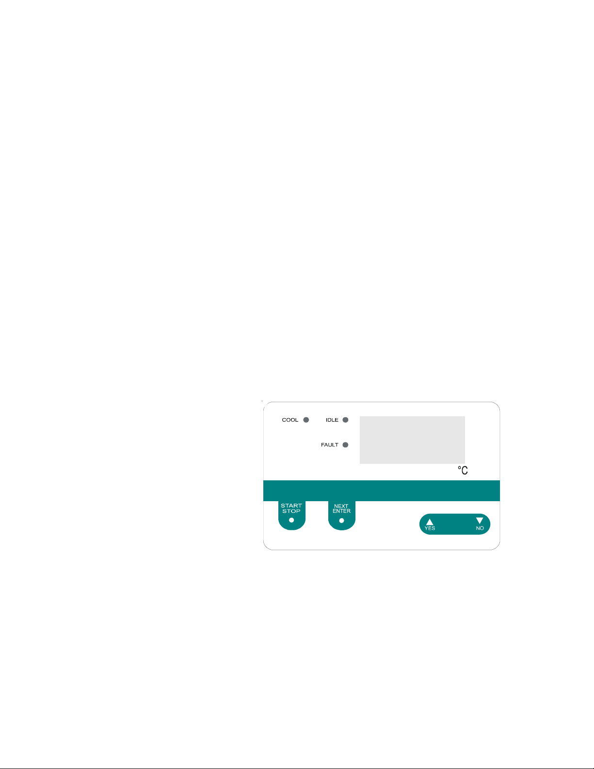
Temperature Controller
To turn the unit off, press START/STOP. The recirculation pump will stop.
The IDLE and COOL lights indicate the control valve’s status. When the
temperature control valve is wide open (for maximum cooling), the COOL
light is on steady. When the control valve is closed, the IDLE light is on. As
the control valve moves between these extremes, the two lights flash with
varying on-time to indicate the approximate position of the control valve.
-11-
Page 16

Temperature Controller
The microprocessor controller controls temperature using a PID (Proportional-Integral-Derivative) algorithm. It is designed with self-diagnostic
features and easy to use operator interface.
NEXT ENTER
Use this key to accept and save changes.
YES,
This key is used to increase numerical values.
NO,
This key is used to decrease numerical values.
When the controller is powered it displays the reservoir fluid temperature.
Press the NEXT ENTER key to view the setpoint. The display flashes
between SP and the actual setpoint number. If desired, use the YES and NO
keys to change the setpoint. The display flashes as soon as either key is
depressed. Once the desired setpoint is displayed, press NEXT ENTER.
When selecting an operating temperature, remember that the lowest achievable temperature is a function of the available flow rate, the temperature of
the cooling water supply and the heat load.
The temperature control system actuates a control valve in the FACILITY
WATER line. The control valve adjusts the flow of the cooling water supply
to produce the desired operating temperature.
NOTE: The controller does not use the new value until the NEXT ENTER
key is depressed and the display stops flashing. The controller will not allow
you to enter a value above the maximum or below the minimum value, or
any illegal value. If you try to enter an illegal value the display will revert to
its original value when the last digit was entered.
If the NEXT ENTER key is not depressed within one minute, the controller
will time out and the new value will not be accepted. The controller will
revert to the previous value.
NOTE: Error codes are addressed in Section VI, Troubleshooting.
-12-
Page 17
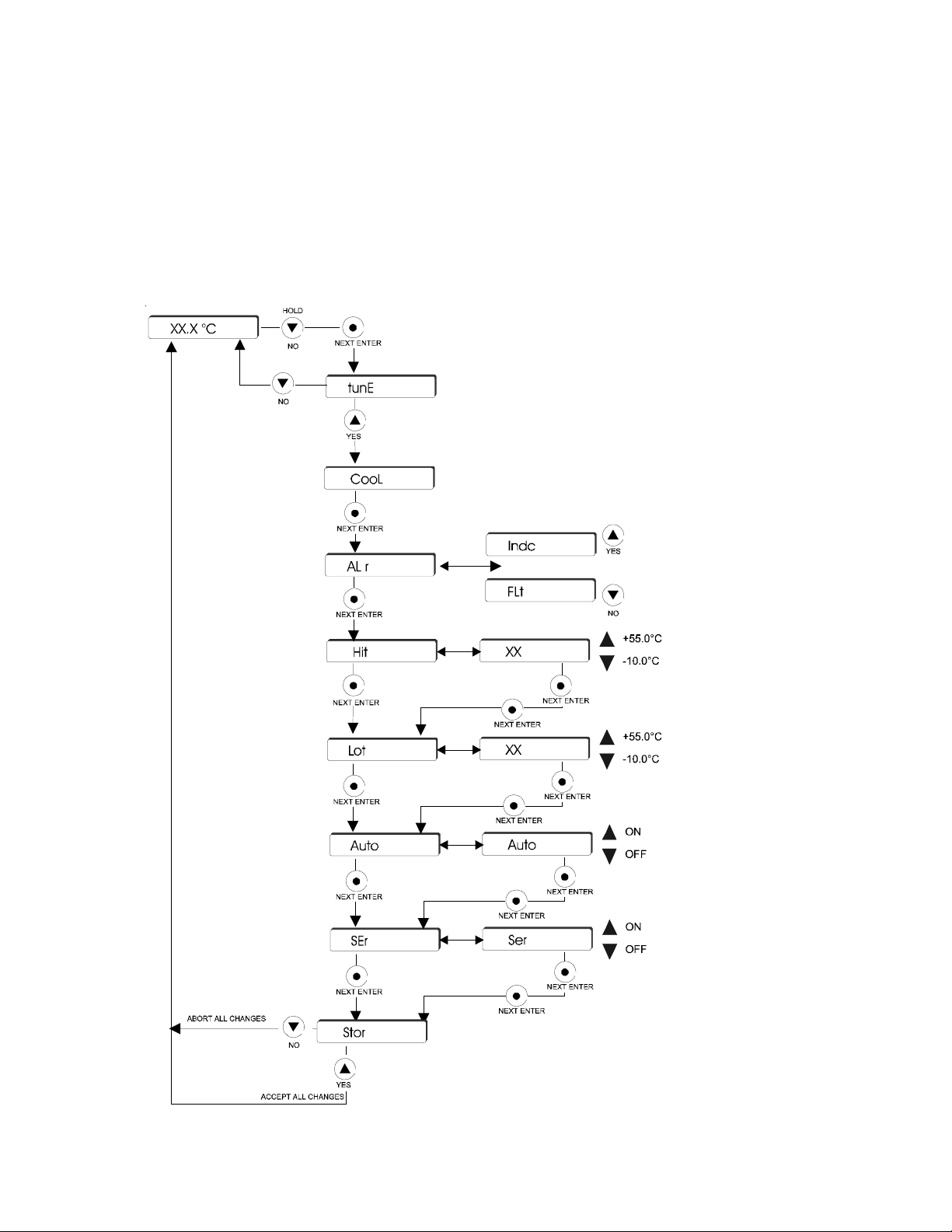
TuneLoop
The controller is used to tune the COOL PID values; configure the unit to
continue to run (Indc) or shut down (FLt) in the event of a fault; set the high
(Hit) and low (Lot) temperature limits; and enable/disable auto restart (Auto).
If a temperature limit is exceeded the controller will display an error code,
see Section VI.
NOTE: Serial Communication (SEr) is not operational. Ensure the display
indicates OFF.
With the controller displaying the fluid temperature, press and
hold the NO key and then press the NEXT ENTER key. The
controller will display tunE. Press YES to display CooL.
CooL is used to adjust the controller's PID values. However ,
Thermo Fisher recommends only a qualified technician change the
PID values. Incorrect values will hamper unit performance. Factory
set values are: P = 15; I = 0.3; D = 0.0.
Press NEXT ENTER to display the
alarm (ALr) prompt. Press YES to
display Indc and have the unit continue
to run in the case of a fault. Press NO to
display FLt and have the unit shut down
in the case of a fault. The factory preset
is FLt.
Press NEXT ENTER to display the
high temp (Hit) alarm setting. If
desired, use the arrow keys to
change the value. The factory
preset value is 55°C.
Setup Loop
Press NEXT ENTER to display the
low temp (Lot) alarm setting. If
desired, use the arrow keys to
change the value. The factory preset
value is -10°C.
Press NEXT ENTER to display the
auto restart (Auto) prompt. Use
the arrow keys enable/disable this
feature. The factory preset is ON.
Press NEXT ENTER to display the
serial comm (SEr) prompt. The
display should flash NO. If not, use
the arrow keys until NO is
displayed.
Press NEXT ENTER to display Stor, press YES
to accept all the changes, press NO to abort all
changes and restore all the previous values. The
controller will again display the fluid temperature.
-13-
Page 18

Service Contracts
Facility Water
Strainer
Section V Maintenance & Service
For personal safety and equipment reliability, the following procedure
should only be performed by a qualified technician. Contact our
Service Department for assistance (see Preface, After-sale Support).
Thermo Fisher Scientific offers on-site Service Contracts that are designed to
provide extended life and minimal down-time for your unit. For more information, contact our Service Department (see Preface, After-sale Support).
The facility water strainer is the user-installed basket strainer on the
FACILITY WATER inlet. NOTE: The strainer is designed to be used only
with water. Clean the strainer when it becomes visibly clogged or dirty.
Disconnect the power cord from the power source and turn off the facility
cooling water.
Algae
Fault Interlock
Contact
Place a container under the strainer to collect any water that spills out of the
basket when it is removed.
Unscrew the clear plastic basket. Remove the screen and rinse it with water.
Replace the screen and the basket.
To restrict the growth of algae in the reservoir, it is recommended that the
reservoir cover be kept in place and that all circulation lines be opaque. This
will eliminate the entrance of light which is required for the growth of most
common algae.
A set of contacts is connected to a receptacle on the control panel. The
contacts are rated 10A/240V. This is not a power inlet or outlet. The
receptacle is isolated from the circuitry. Its ground pin is connected to the
chassis. The contacts are closed during normal operation and open when
the unit is turned off or when a fault is detected.
-14-
Page 19

Configuration
Voltage Selection
(60 Hertz Units)
The unit top is secured to the cabinet by four ball stud retainers; one at each
corner. Remove cabinet top by prying upward gently (cover pops off) in
order to perform the following adjustments.
In some cases, the side access panels may need to be removed. The
access panels are secured using screws installed through the bottom of the
cabinet.
NOTE Units rated 380-415 volt do not have a voltage selection switch.
Remove the top cover from the cabinet as described in Configuration.
The VOLTAGE SELECT toggle switch is located on the right side of the
control box. Two ranges are available: 200-208V and 220-240V. Set the
switch for the appropriate range.
Replace the top cover.
Fuses
Phase Rotation
The main fuses are 20 Amp RK5. The controller fuses are 1 Amp time delay.
Do not replace with an alternate amperage.
Single Phase Units
Remove the top cover from the cabinet.
The fuses are located on the right side of the control box.
Three Phase Units
Remove the top cover, the right access panel and the control box cover.
The fuses are located inside the control box.
Three phase units with three phase pump motors are equipped with a phase
rotation interlock. If the phasing is wrong, the controller will display PHEr and
the unit will not start.
Unplug the unit. Reverse any two power cord wires in the power cord plug.
Never remove the green ground wire.
Plug in the unit. The PHEr display should be off and the unit should start.
-15-
Page 20

Pump Motor
Overload Protector
Displaying Software
Version
Three phase units with three phase pump motors have a pump motor
overload protector.
The overload protector prevents the pump motor from exposure to
excessively high current. If an overload fault occurs, due, for example, to a
heavy work load, the controller will display OL and the unit will shut down.
The overload protector will automatically reset after about two minutes. The
unit must be manually restarted.
This procedure will display the software version number on the unit’s display.
In the event the unit is not operational, the software version (and the checksum) can also be read from the label which is on the microprocessor chip
itself.
The following chart uses an example of software version 000550.93A
begin at the reservoir temperature display 20.3°C
Press and hold NO for at least 10 seconds. 0550
displays software version digits to left of decimal. Note the two leading zeros
do not display.
Press NEXT 93
displays software version digits to right of decimal.
Press NEXT 1
displays software version revision letter (as its equivalent number - display
cannot show letters. A=1, B=2, etc.)
Press NEXT 0000
displays checksum - this can be disregarded
Press NEXT 20.3°C
returns to reservoir temperature display
-16-
Page 21

Error Codes
Section VI T roubleshooting
The controller also has the capability to display error codes.
Power up Errors
Power up errors are displays until any controller key is pressed. If the error
message persists the problem is likely a keypad or controller board failure.
Display Indication
Er 00 ROM checksum
Er 01 RAM check
Er 02 Keypad failure
Er 03 NOVRAM checksum error
Operating Errors
Operating errors are displays once and then clear after three seconds or
when any controller key is pressed. If error messages Er04 - Er14 persist,
the problem is likely controller board failure. If Er15 is displayed, ensure
serial communications is turned off in the Setup Loop. If Er16 is displayed
the unit needs calibration, contact us for assistance.
Display Indication
Er 04 - 13 Interrupt error
Er 14 Synchronous error
Er 15 Asynchronous error
Er 16 Bad calibration
Latching Errors
In order to restart the unit when a latching error is displayed, the controller's
START/STOP button must be pressed after the condition is cleared.
Display Indication
Lo t Fluid temperature lower than low temp alarm setting.
Hi t Fluid temperature higher than high temp alarm setting .
Er 22 Fluid temperature higher than the high overrange point.
This is a fixed value, factory set at 55°C.
Er 25 RDT1 input shorted.
Er 26 RTD1 input open.
LLF Low level fault switch open for at least three seconds.
PHEr Improper phasing.
OL Pump motor overload.
If any other code appears contact Thermo Fisher Scientific customer service,
see Preface.
-17-
Page 22

Service Assistance
Technical Support
If, after following these troubleshooting steps, your units fails to operate
properly, contact our Service Department for assistance (see Preface, Aftersale Support). Before calling please obtain the following information:
Part number
Serial number
Voltage of unit
Voltage of power source
Software Version
Our Service Department can provide you with a complete list of spare parts
for your unit (see Preface, After-sale Support). Before calling, please obtain
the following information:
Part number
Serial number
-18-
Page 23
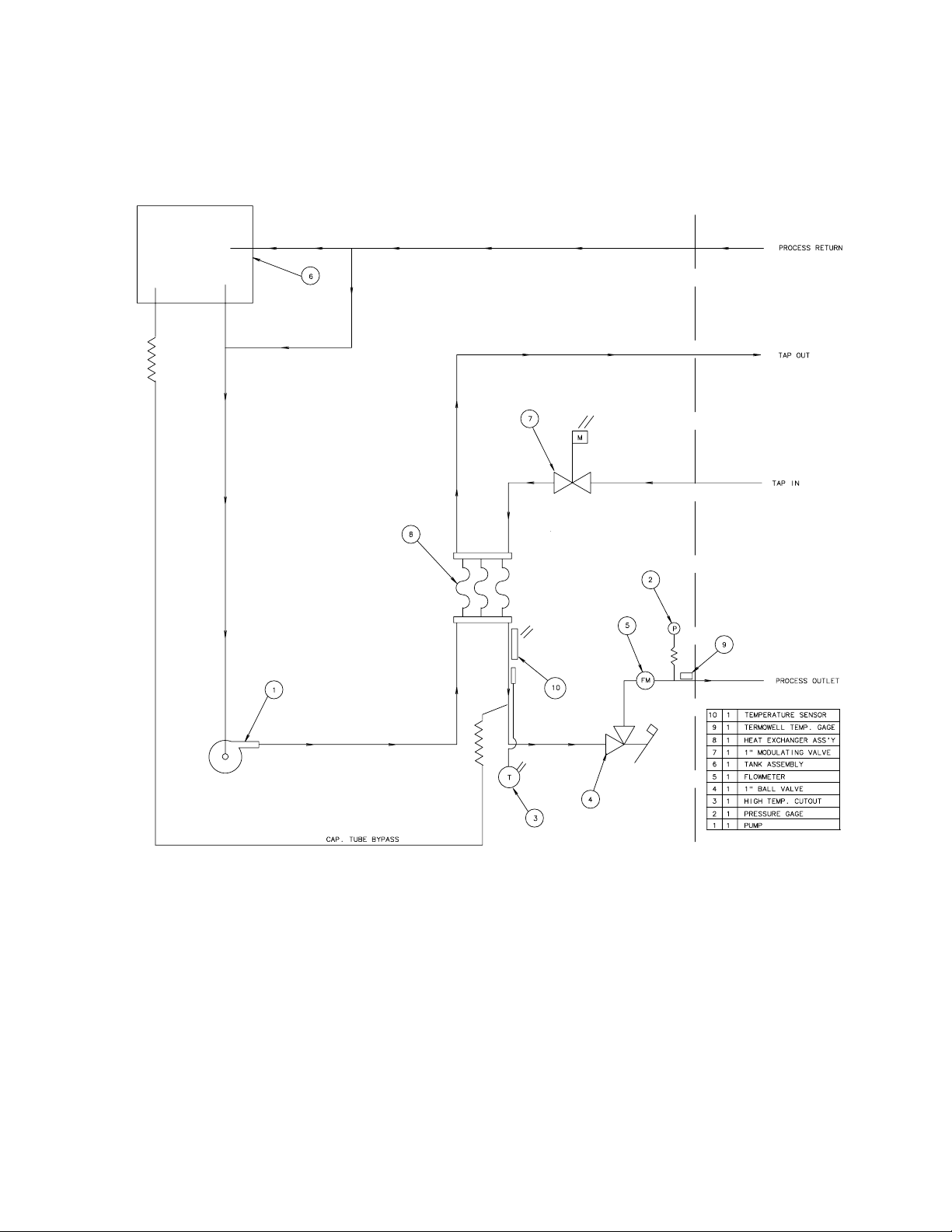
Flow Diagram
Section VII Diagrams
-19-
Page 24
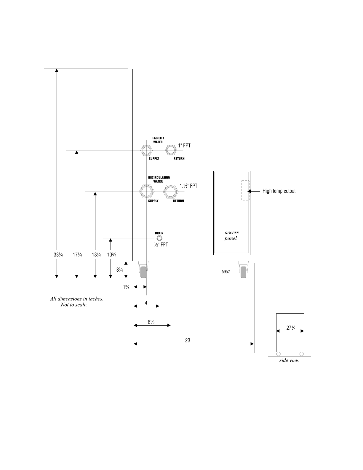
Rear View
-20-
Page 25

Water Quality Standards
and Recommendations
Microbiologicals
(algae, bacteria, fungi) 0 0
Inorganic Chemicals
Calcium <40 <0.6
Chloride 250 <25
Copper <1.3 <1.0
Iron <0.3 <0.1
Lead <0.015 0
Magnesium <12 <0.1
Manganese <0.05 <0.03
Nitrates\Nitrites <10 as N 0
Potassium <20 <0.3
Silicate <25 <1.0
Sodium <20 <0.3
Sulfate <250 <50
Hardness <17 <0.05
Total Dissolved Solids <50 <10
Other Parameters
pH 6.5-8.5 7-8
Resistivity 0.01* 0.05-0.1*
* MOhmcm (Compensated to 25°C)
Appendix
Permissible (PPM) Desirable (PPM)
Unfavorably high total ionized solids (TIS) can accelerate the rate of galvanic corrosion. These contaminants can function as electrolytes which increase the potential for galvanic cell corrosion and lead to
localized corrosion such as pitting. Eventually, the pitting could become so extensive that leaking will
occur between the process water and facility water diminishing the System's heat transfer capability.
High water hardness (Calcium and Maganese) can also produce scaling. Scaling will inhibit heat transfer
between the process and facility side by building up a deposit layer on metal surfaces. As an example,
raw water in the United States averages 171 ppm (of NaCl). The recommended level for use in a water
system is between 0.5 to 5.0 ppm (of NaCl).
Recommendation: Initially fill the tank with distilled/deionized water. Do not use untreated tap water as
the total ionized solids level may be too high.
The desired level for long time usage is 1 to 3 MOhmcm (compensated to 25°C).
The above recommendations will reduce the electrolytic potential of the water and prevent or reduce the
galvanic corrosion observed.
Not Recommended, Increasingly Corrosive
15.00
10.00
3.00
Operations with Stainless Steel Systems
1.00
Resistivity (MOhmcm @ 25°C)
0.10
0.05
Operations with
Mixed Metals
Copper/Brass/
Stainless Steel
10 20 30 40 50 60 70 80
CONSULT MATERIALS ENGINEER
°C
Temperature
-21-
Page 26

WARRANTY
Thermo Fisher Scientific warrants for 12 months from date of shipment any Thermo Scientific System
product according to the following terms.
Any part of the unit manufactured or supplied by Thermo Fisher and found in the reasonable judgment of Thermo
Fisher to be defective in material or workmanship will be repaired at an authorized Thermo Scientific Product
Repair Depot without charge for parts or labor. The unit, including any defective part must be returned to an
authorized Thermo Scientific Product Repair Depot within the warranty period. The expense of returning the unit
to the authorized Thermo Scientific Product Repair Depot for warranty service will be paid for by the buyer. Our
responsibility in respect to warranty claims is limited to performing the required repairs or replacements, and no
claim of breach of warranty shall be cause for cancellation or recision of the contract of sales of any unit. With
respect to units that qualify for field service repairs, Thermo Fisher Scientific’s responsibility is limited to the
component parts necessary for the repair and the labor that is required on site to perform the repair. Any travel
labor or mileage charges are the financial responsibility of the buyer.
The buyer shall be responsible for any evaluation or warranty service call (including labor charges) if no defects
are found with the Thermo Scientific product.
This warranty does not cover any unit that has been subject to misuse, neglect, or accident. This warranty does
not apply to any damage to the unit that is the result of improper installation or maintenance, or to any unit that
has been operated or maintained in any way contrary to the operating or maintenance instructions specified in
this Instruction and Operation Manual. This warranty does not cover any unit that has been altered or modified
so as to change its intended use.
In addition, this warranty does not extend to repairs made by the use of parts, accessories, or fluids which are
either incompatible with the unit or adversely affect its operation, performance, or durability.
Thermo Fisher Scientific reserves the right to change or improve the design of any product without assuming any
obligation to modify any unit previously manufactured.
THE FOREGOING EXPRESS WARRANTY IS IN LIEU OF ALL OTHER WARRANTIES, EXPRESSED OR
IMPLIED, INCLUDING BUT NOT LIMITED TO WARRANTIES OR MERCHANTABILITY AND FITNESS FOR A
PARTICULAR PURPOSE.
Thermo Fisher Scientific's OBLIGATION UNDER THIS WARRANTY IS STRICTLY AND EXCLUSIVELY LIMITED
TO THE REPAIR OR REPLACEMENT OF DEFECTIVE COMPONENT PARTS AND Thermo Fisher DOES NOT
ASSUME OR AUTHORIZE ANYONE TO ASSUME FOR IT ANY OTHER OBLIGATION.
Thermo Fisher ASSUMES NO RESPONSIBILITY FOR INCIDENTAL, CONSEQUENTIAL, OR OTHER DAMAGES INCLUDING, BUT NOT LIMITED TO LOSS OR DAMAGE TO PROPERTY, LOSS OF PROFITS OR
REVENUE, LOSS OF THE UNIT, LOSS OF TIME, OR INCONVENIENCE.
This warranty applies to units sold in the United States. Any units sold elsewhere are warranted by the affiliated
marketing company of Thermo Fisher Scientific. This warranty and all matters arising pursuant to it shall be
governed by the law of the State of New Hampshire, United States. All legal actions brought in relation hereto shall
be filed in the appropriate state or federal courts in New Hampshire, unless waived by Thermo Fisher Scientific.
Page 27

Page 28

Thermo Fisher Scientific
81 Wyman Street
P.O. Box 9046
Waltham, Massachusetts 02454-9046
United States
www.thermofisher.com
 Loading...