

Page 1

Thermo Scientific
User Manual
Orion Star A210 Series
Electrochemistry Benchtop Meters
68X000441 • Revision A • June 2015
Page 2

mportant Note
I
Please read this user guide thoroughly before using your meter. Any use
outside of these instructions may invalidate your warranty and cause
permanent damage to the meter.
Page 3

Table of Contents
Chapter 1 ....................................................................................................................... 6
Meter Introduction ........................................................................................................ 6
Meter Overview ............................................................................................................................ 6
Packing List ................................................................................................................................. 7
Intended Use ............................................................................................................................... 7
Chapter 2 ....................................................................................................................... 8
Meter Basics ................................................................................................................. 8
Using the Universal Power Adapter ............................................................................................. 8
Installing Batteries (Optional Power Source) ............................................................................... 9
Attaching the Electrode Stand and Holder ................................................................................. 10
Using the Electrode Holder .............................................................................................. 11
Meter Connections ..................................................................................................................... 12
Meter Keypad ............................................................................................................................ 14
Function Keys .................................................................................................................. 15
Meter Display ............................................................................................................................. 16
Measurement Display Icons ............................................................................................. 18
pH Electrode Condition Icon ............................................................................................. 18
Meter Models and Measurement Capabilities ............................................................................ 19
Meter Maintenance .................................................................................................................... 19
Chapter 3 ..................................................................................................................... 20
Meter Setup Menus ..................................................................................................... 20
Main Setup Menu ....................................................................................................................... 20
General Setup Menu Navigation ...................................................................................... 20
Channel-Specific Method, Mode and Temperature Menus........................................................ 24
Method Menu ................................................................................................................... 25
Mode and Settings Menu ................................................................................................. 28
Temperature Menu ........................................................................................................... 41
Instrument Settings Setup Menu................................................................................................ 45
Log View Menu .......................................................................................................................... 46
Data Log ........................................................................................................................... 46
Calibration Log ................................................................................................................. 47
D
iagnostics Menu ...................................................................................................................... 48
Meter Self Test Procedure ............................................................................................... 48
Electrode Stability Test Procedure ................................................................................... 49
Chapter 4 ..................................................................................................................... 50
Using the pH or pH/ISE Channel ............................................................................... 50
Meter and Electrode Preparation ............................................................................................... 50
pH Calibration Procedure .......................................................................................................... 51
pH Calibration Editing....................................................................................................... 52
ORP Calibration Procedure (Relative mV Mode) ....................................................................... 53
ORP Calibration Procedure (E
ISE Calibration Procedure ......................................................................................................... 55
ISE Calibration Editing ..................................................................................................... 56
Measurement Procedure ........................................................................................................... 57
Units) ....................................................................................... 54
H
Page 4

Chapter 5 ..................................................................................................................... 58
Using the Conductivity Channel ............................................................................... 58
Meter and Sensor Preparation ................................................................................................... 58
Conductivity Calibration Procedure ............................................................................................ 59
Conductivity Calibration Editing ........................................................................................ 60
Alternative Certified Cell Constant Entry Calibration Procedure ...................................... 60
Conductivity Standards vs. Temperature Table ......................................................................... 61
Conductivity Meter Verification Procedure ................................................................................. 62
Measurement Procedure ........................................................................................................... 63
Chapter 6 ..................................................................................................................... 64
Using the DO/RDO Channel ....................................................................................... 64
Meter and Sensor Preparation ................................................................................................... 64
Dissolved Oxygen Calibration Procedure .................................................................................. 65
Air (Water-saturated Air) Calibration ................................................................................ 66
Water (Air-saturated Water) Calibration ........................................................................... 66
Manual (Winkler) Calibration ............................................................................................ 67
Set Zero Calibration ......................................................................................................... 68
Measurement Procedure ........................................................................................................... 69
Chapter 7 ..................................................................................................................... 70
Data Transfer and Software Updates ........................................................................ 70
Data Storage and Transfer Settings .......................................................................................... 70
Measurement Read Type Setting ..................................................................................... 70
Data Log Setting .............................................................................................................. 71
Export Data Settings ........................................................................................................ 72
Printer Compatibility and Requirements .................................................................................... 74
Computer Compatibility and Requirements ............................................................................... 75
Using the USB-to-Serial Computer Cable ........................................................................ 76
Using the USB Computer Cable ....................................................................................... 78
Orion Star Com Communication Software ....................................................................... 81
Meter Interfacing with Other Computer Programs ............................................................ 82
Star A200-A300 Meter Remote Control Protocols ............................................................ 83
Meter Software Upgrade Procedure .......................................................................................... 90
Chapter 8 ..................................................................................................................... 94
Customer Services ..................................................................................................... 94
Troubleshooting Tips ................................................................................................................. 95
Meter Factory Reset Procedure ....................................................................................... 96
Meter User Reset Procedure ............................................................................................ 96
Notice of Compliance ................................................................................................................. 97
WEEE Compliance .................................................................................................................... 97
Declaration of Conformity .......................................................................................................... 98
Meter Specifications .................................................................................................................. 99
Ordering Information ................................................................................................................ 106
Meter Accessories, Electrodes and Solutions ................................................................ 108
Page 5

Page 6

1
CHAPTER 1
Meter Introduction
Meter Overview
Thermo Scientific™ Orion Star™ A210 series benchtop meters feature an informat ive, easy to
read graphic display with backlight and onscreen calibration and setup instructions for intuitive,
user-friendly operation with minimum training. The comprehensive keypad with menu-specific
function keys and useful shortcut keys allows fast and efficient meter navigation and control.
The multilanguage user interface allows customization of the meter in a variety of local
languages and new languages can be added through software updates.
Measurements can be taken quickly and reliably with the onscreen re a ding st ab ilit y ind icat or
and selectable read modes – Auto-Read, timed or continuous with hold function. The data log
collects up to 2000 measurement sets with time and date stamp and the non-volatile meter
™
memory preserves all data, even with the loss of power. Use Thermo Scientific
™
software to facilitate data transfer from the meter to a computer via USB or RS232,
Com
export data to an Excel spreadsheet or comma separated value file (.csv) and print data to a
network or local printer.
Orion™ Star
Utilize the Orion Star stirrer probe for meter-powere d and meter-contr o lled sample stirri ng w ith
five selectable stirring speeds. Use the stirrer probe with the included electrode stand to simplify
placement into and out of solutions and eliminate the need for magnetic stir bars and plates.
The IP54-rated dust and splash resistant meter housing offers the flexibility to place the meter
where it is needed – on the bench or wall-mounted to save space. For added site adaptability,
power the meter using the included universal power adapter or optional four AA batteries. Six
Orion Star A210 series benchtop meters are available to meet your exact measurement needs.
6 | Orion Star A210 Series Benchtop Meter User Manual Thermo Scientific
Page 7

Chapter 1 | Meter Introduction
Orion Star A211 pH Benchtop Meter
Measure pH, mV, relative mV or ORP with temperature
Orion Star A212 Conductivity Meter
Measure conductivity, TDS, salinity or resistivity with temperature
Orion Star A213 RDO/DO Meter
Measure dissolved oxygen as % saturation or concentration with temperature using either
®
optical or polarographic DO sensors
RDO
Orion Star A214 pH/ISE Meter
Measure ion concentration using an ion selective electrode (ISE), pH, mV, relative mV or ORP
with temperature
Orion Star A215 pH/Conductivity Meter
Measure pH, mV, relative mV or ORP with temperature on channel one and
measure conductivity, TDS, salinity or resistivity with temperature on channel two
Orion Star A216 pH/RDO/DO Meter
Measure pH, mV, relative mV or ORP with temperature on channel one and
measure dissolved oxygen as % saturation or concentration with temperature on channel two
Packing List
Orion Star A210 series benchtop meters and meter kits include the following items:
• Meter-attachable electrode stand and holder
• Universal power adapter
• Literature CD
• Printed quick start guide
• Computer interface cable
• Meter test certificate
Each Orion Star A210 series meter is fully tested and certified by Thermo Fisher Scientific and
a certificate of calibration is included with each meter. For specifi c meter and kit contents, refer
to the
Ordering Information section. Visit our website at www.thermoscientific.com/OrionMeters
to download the complimentary Orion Star Com data transfer computer software and Star
A200/A300 series USB driver.
Intended Use
Please read this reference guide thoroughly. Any use outside of these instructions may
invalidate the meter warranty and cause permanent damage to the meter.
Thermo Scientific Orion Star A210 Series Benchtop Meter User Manual | 7
Page 8

2
CHAPTER 2
Meter Basics
Using the Univer sal Power Adapter
A universal power adapter (Catalog Number 1010003) with US, EU, UK and China plug plates
is included with the Orion Star A210 series benchtop meters. This universal power adapter is
specifically for use with Star A210 series benchtop meters. Use of other power adapters can
damage the meter and void the warranty.
1. Select the appropriate plug plate for the power outlet that will be used.
2. Remove the clear plastic cover from the groove on the back of the power adapter.
3. Slide the appropriate plug plate into the groove on the back of the power adapter.
4. Connect the assembled power adapter to a power outlet and the meter input labeled Power.
surge protector or uninterrupted power supply (UPS) is also recommended.
A
8 | Orion Star A210 Series Benchtop Meter User Manual Thermo Scientific
Page 9

Chapter 2 | Meter Basics
Installing Batteries (Optional P ower Source)
1. Select four new AA alkaline batteries.
2. Confirm that the meter is powered off.
3. Turn the meter over, with the meter display facing down, on a clean dry surface.
4. Remove the battery compartment cover – push down on the battery compartment tab and
lift the battery compartment cover up.
5. Install the new batteries in the battery compartment, orientating the batteries as shown in
the battery compartment housing.
6. Replace the battery compartment cover and turn the meter over, with the meter displa
f
acing up.
y
Thermo Scientific Orion Star A210 Series Benchtop Meter User Manual | 9
Page 10
Chapter 2 | Meter Basics
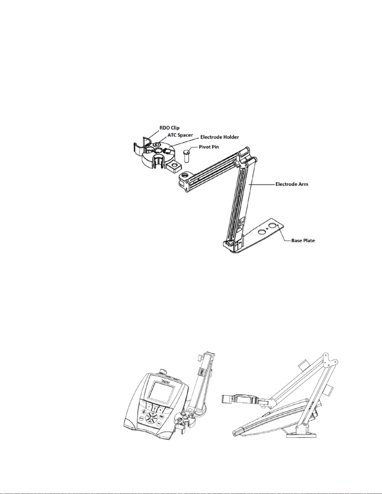
Attaching the Electrode Stand and Holder
The electrode stand can be attached to either side of the meter and up to two stands can be
attached to each meter. A weighted base (Catalog Number STARA-HB) is also available to
support the stand without attachment to the meter.
1. Open the box containing the electrode stand. The box will include a base plate, electrode
arm, pivot pin, electrode holder, ATC spacer and RDO clip.
2. Turn the meter over, with the meter display facing down, on a clean dry surface.
3. Identify the side of the meter that the stand will be installed on and remove the screw
between the circles on that side of the meter
. Align the base plate of the stand with the circles on the meter.
4
5. Replace the screw from step 3 to attach the base plate to the meter.
6. Turn the meter over, with the meter display facing up.
7. Insert the electrode arm into the metal post on the base plate.
8. Connect the electrode holder to the electrode arm using the pivot pin.
.
10 | Orion Star A210 Series Benchtop Meter User Manual Thermo Scientific
Page 11

Chapter 2 | Meter Basics
12 mm holder with optional ATC
probe insert
Stirrer probe holder
Holder with 20° angle for gas
sensing ion selective electrodes
Optional RDO optical dissolved
oxygen sensor holder
12 mm flexible holder for pH, ORP
and ion selective electrodes
15 mm holder for conductivity and
dissolved oxygen sensors
Using the Electrode Holder
Place electrodes in the stand for easy movement in and out of containers during calibration,
sample measurement and storage. Recommended electrode positions are shown below.
Thermo Scientific Orion Star A210 Series Benchtop Meter User Manual | 11
Page 12
Chapter 2 | Meter Basics
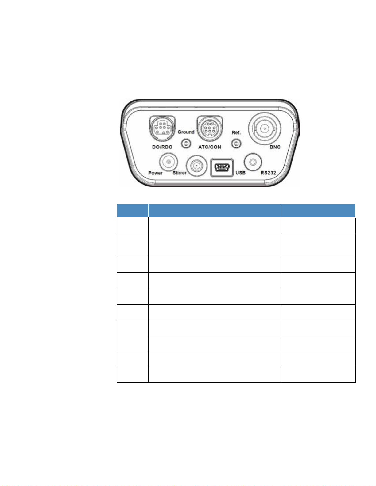
Connect the universal power adapter (included with
meter) to power the meter
Connect an Orion Star stirrer probe (Catalog Number
stirring with five selectable speeds
Connect the USB cable for bi-directional data transfer
and communication via USB to a printer or computer
Connect the RS232 cable for bi-directional data transfer
and communication via RS232 to a printer or computer
Connect a pH electrode, ORP/redox electrode or ion
selective electrode (ISE) with BNC connector
Star A211, Star A214,
Star A215, Star A216 meters
Connect a half-cell reference electrode with standard 2.5
mm pin-tip connector
Star A211, Star A214,
Star A215, Star A216 meters
Connect an ATC temperature probe with 8 pin MiniDIN
connector
Star A211, Star A214,
Star A216 meters
Connect a conductivity sensor or ATC temperature probe
with 8 pin MiniDIN connector
Connect a dissolved oxygen sensor (either RDO optical
or polarographic) with 9 pin MiniDIN connector
Meter Connections
The following diagram depicts all the possible meter connections available on the Orion Star
A210 series benchtop meters. Some Star A210 series benchtop meters will have fewer
connections, depending on the meter’s measurement capabilities.
Connector Function Applicable Meter Models
Power
Stirrer
USB
RS232
BNC
Ref.
ATC/CON
Ground Use to reduce interference generated by other equipment All Star A210 series meters
DO/RDO
096019) for meter-controlled and meter-powered sample
All Star A210 series meters
All Star A210 series meters
All Star A210 series meters
All Star A210 series meters
Star A212, Star A215 meters
Star A213, Star A216 meters
Orion Star A210 series benchtop meters are compatible with the same electrodes and sensors
used with Thermo Scientific
Star
pH/ATC electrodes, Thermo Scientific
Orion
12 | Orion Star A210 Series Benchtop Meter User Manual Thermo Scientific
™
Orion™ Versa Star™ meters and legacy Thermo Scientific™ Orion
™
and Star Plus meters. This includes the Thermo Scientific™ Orion™ ROSS Ultra™ Triode™
™
Orion™ ROSS™ pH electrodes and Thermo Scientific™
™
DuraProbe™ conductivity sensors.
Page 13
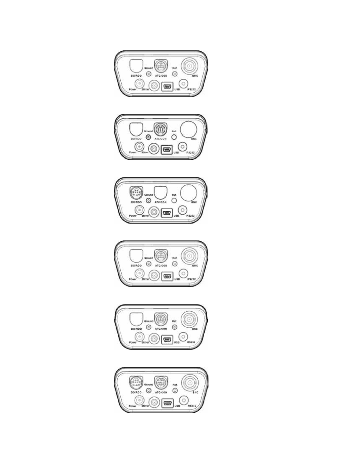
Orion Star A211 pH Meter Connections
Orion Star A212 Conductivity Meter Connections
Orion Star A213 RDO/DO Meter Connections
Chapter 2 | Meter Basics
Orion Star A214 pH/ISE Meter Connections
Orion Star A215 pH/Conductivity Meter Connections
Orion Star A216 pH/RDO/DO Meter Connections
Thermo Scientific Orion Star A210 Series Benchtop Meter User Manual | 13
Page 14
Chapter 2 | Meter Basics
f1, f2, f3
Press the power key to turn on the meter.
Press the measure (esc) key in the Auto-Read measurement mode to start
log view
stirrer
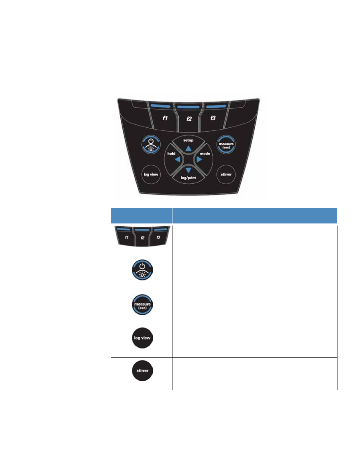
Meter Keypad
The Orion Star A210 series benchtop meter keypad includes menu-specific function keys that
update on the display for fast and efficient meter operation and shortcut keys for easy
navigation to the measurement, setup, data log and calibration log menus.
Key Icon and Name Function
Press the f1, f2 and f3 function keys to perform the action shown above
each key on the display.
When the meter is powered on, press and release the power key to switch
the display backlight on and off.
er
pow
easure (esc)
m
Pr
ess and hold the power key for about three seconds to turn off the meter.
a new measurement.
Press the measure (esc) key to escape the current mode or menu and
return to the measurement mode.
Press the log view key to access the data log and calibration log from the
measurement mode.
Press the stirrer key to turn the stirrer probe on and off in the continuous or
timed measurement mode and the calibration edit mode.
14 | Orion Star A210 Series Benchtop Meter User Manual Thermo Scientific
Page 15
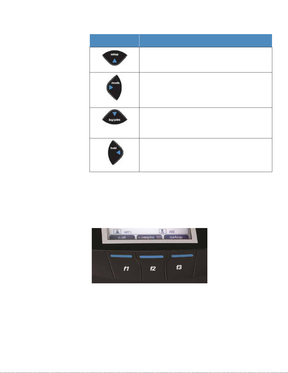
Key Icon and Name Function
setup / up arrow (p)
mode / right arrow (u)
(q)
Hold / left arrow (t)
Press the setup key to enter the setup menu from the measurement mode.
Press the up arrow (p) key to scroll up through a list of items.
Press the mode key to change the measurement mode of the displayed
channel.
Press the right arrow (u) key to sc roll right through a list of items.
Press the log/print key to manually log and/or print a measurement,
depending on the selected measurement mode and data output settings.
log/print / down arrow
Press the down arrow (q) key to scroll down through a list of items.
In the continuous measurement mode, press the hold key to lock (freeze)
the current displayed measurement and press the hold key again to release
(unfreeze) the measurement.
Press the left arrow (t) key to scroll left through a list of items.
Chapter 2 | Meter Basics
Function Keys
The following image shows the f1, f2 and f3 keys with their corresponding actions above each
function key on the meter display. Pressing the f1 (cal) key will prompt the meter to enter the
calibration mode. Pressing the f2 (sample ID) key will prompt the meter to enter the sample ID
setup mode. Pressing the f3 (setup) key will prompt the meter to enter the main setup menu.
Thermo Scientific Orion Star A210 Series Benchtop Meter User Manual | 15
Page 16
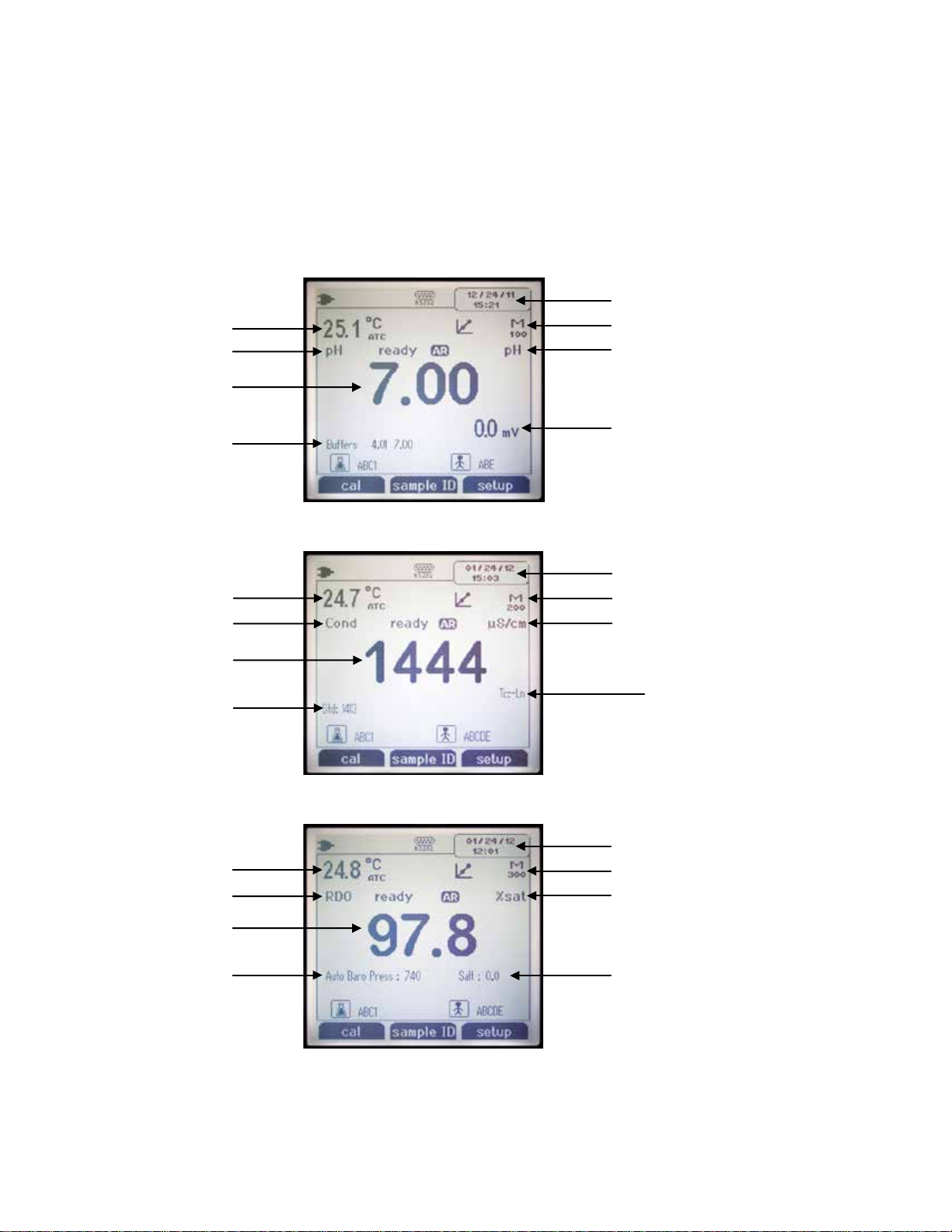
Chapter 2 | Meter Basics
Date and time
Method
mV corresponding to main measurement
Main measurement units
Main measurement mode
Calibration points from most
recent active calibration
Main measurement value
Temperature measurement
and source
Date and time
Method
Main measurement units
Main measurement mode
Calibration points from most
recent active calibration
Main measurement value
Temperature measurement
and source
Temperature compensation setting
Date and time
Method
Main measurement mode
Barometric pressure
Main measurement value
Temperature measurement
and source
Salinity value
Main measurement units
Meter Display
Measurement Display Examples
The following displays are examples only. Actual meter displays will vary based on the selected
meter setup parameters, active calibration data, etc.
Orion Star A211 pH Measurement Display
Orion Star A212 Conductivity Meter Display
Orion Star A213 RDO/DO Meter Display
16 | Orion Star A210 Series Benchtop Meter User Manual Thermo Scientific
Page 17
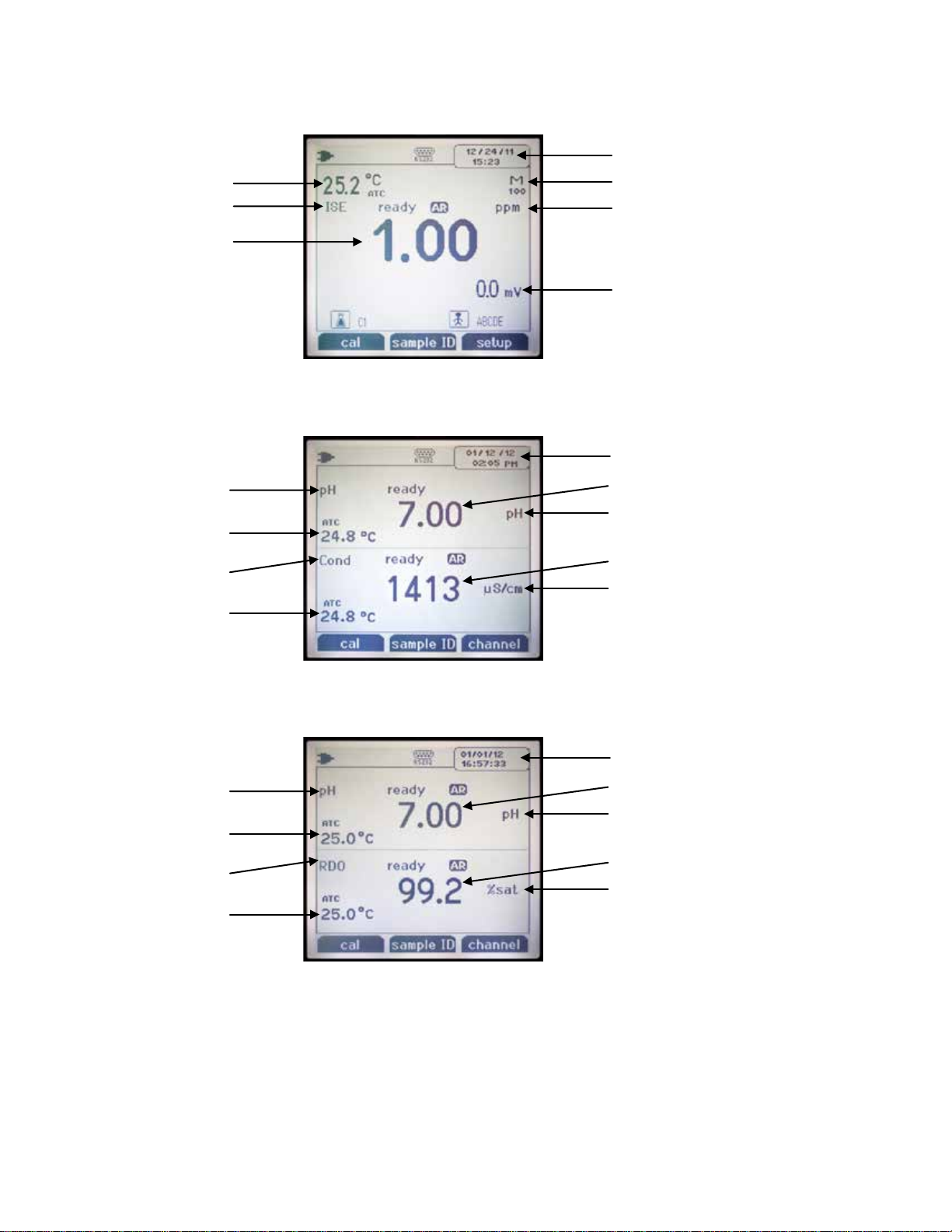
Chapter 2 | Meter Basics
Date and time
Method
mV corresponding to main measurement
Main measurement units
Main measurement mode
Main measurement value
Temperature measurement
and source
Channel 2 main measurement value
Channel 2 main measurement units
Channel 2 main
measurement mode
Channel 1 main
measurement mode
Channel 1 main measurement value
Channel 1 main measurement units
Date and time
Channel 1 temperature
measurement and source
Channel 2 temperature
measurement and source
Channel 2 main measurement value
Channel 2 main measurement units
Channel 2 main
measurement mode
Channel 1 main
measurement mode
Channel 1 main measurement value
Channel 1 main measurement units
Date and time
Channel 1 temperature
measurement and source
Channel 2 temperature
measurement and source
Orion Star A214 pH/ISE Meter Display
Orion Star A215 pH/Conductivity Meter Display
Display each channel separately or both channels simultaneously using the f3 (channel) key.
Orion Star A216 pH/RDO/DO Meter Display
Display each channel separately or both channels simultaneously using the f3 (channel) key.
Thermo Scientific Orion Star A210 Series Benchtop Meter User Manual | 17
Page 18
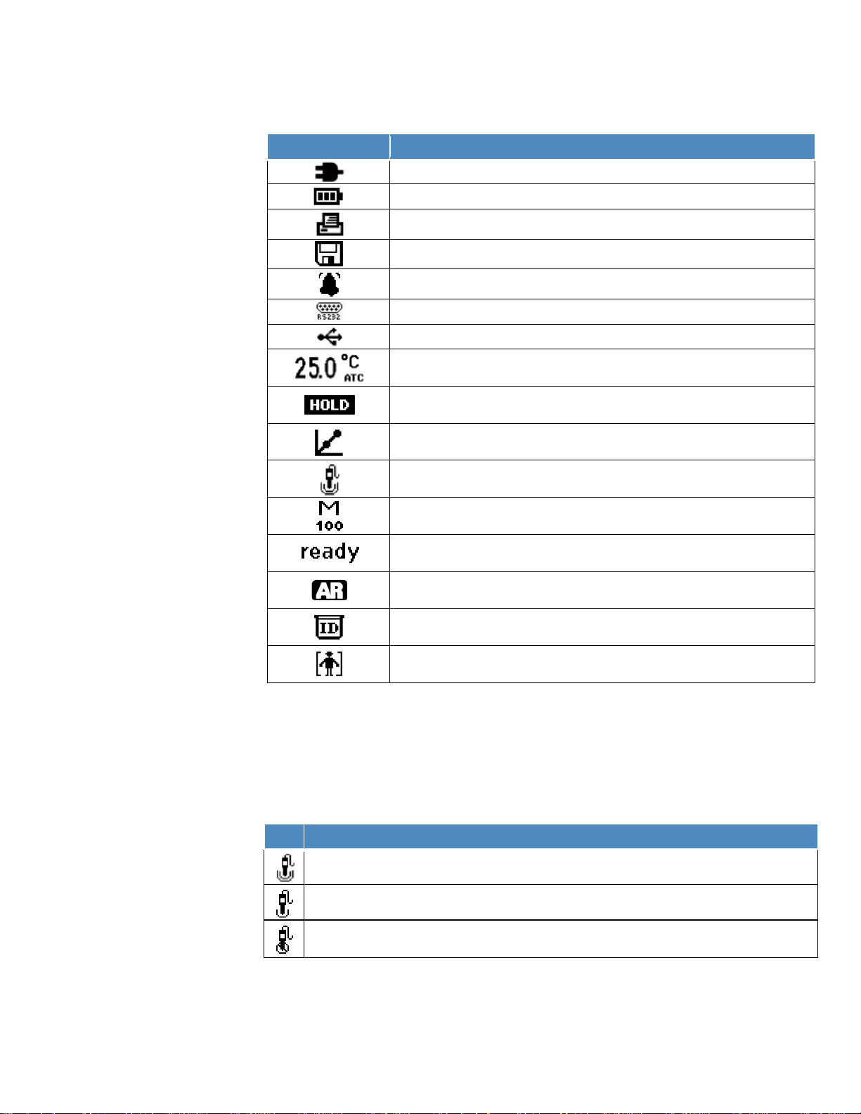
Chapter 2 | Meter Basics
Display Icon
Description
Shown when the meter is running on AC power
Shown when the meter is running on battery power
Indicates the RS232 port is selected for printer or computer interfacing
Indicates the USB port is selected for printer or computer interfacing
Displays the active temperature measurement and indicates the source as an
ATC temperature sensor (ATC) or manually entered temperature value (MAN)
Shown when the hold key is pressed and displayed measurements are frozen,
press the hold key a second time to release the hold function
Indicates a calibration has been successfully completed, flashes when the
calibration alarm is set and the alarm is triggered
Indicates the pH electrode condition as good (two bars), fair (one bar) or bad
(slash through it), based on the last saved calibration and electrode stability
Indicates the active measurement method number, M100 and M200 are the
default methods and indicate a password-protected method is not in use
Stability indicator will flash stabilizing while the measurement is changing and
show ready when the measurement is stable
When the read type is set to Auto-Read, the icon will flash while the reading is
stabilizing and remain solid when the reading is stable and locked on the display
Indicates the sample ID function is active, the operator assigned number is
shown to the right of the icon
Indicates the user ID function is active, the operator assigned name is shown to
the right of the icon
Icon
pH Electrode Status
Electrode condition is bad. The electrode slope is 85% or lower or 115% or higher. Consult the
pH electrode manual for instructions on how to clean, condition and troubleshoot the electrode.
Measurement Display Icons
Indicates when data is exported to a computer or printer
Indicates when a measurement is recorded in the data log
Shown when an alarm is set and the alarm is triggered
pH Electrode Condition Icon
Orion Star A211 pH meters, Orion Star A214 pH/ISE meters, Orion Star A215 pH/conductivity
meters and Orion Star A216 pH/RDO/DO meters include a pH electrode condition icon. In the
measurement mode, the pH electrode condition icon indicates the performance of the pH
electrode, based on the last saved calibration and electrode measurement stability.
Electrode condition is good. The electrode slope is in the range of 95.1% to 104.9%.
Electrode condition is fair. The electrode slope is 85.1% to 95% or 105% to 114.9%.
Note: This is a general indicator of overall electrode status – always refer to the pH electrode
user manual for specific information on the recommended slope range for each pH electrode.
18 | Orion Star A210 Series Benchtop Meter User Manual Thermo Scientific
Page 19

Chapter 2 | Meter Basics
Channel 1
Measurement Modes
Channel 2
Measurement Modes
pH
mV
Automatic
RmV
Manual
ORP
Conductivity
TDS
Automatic
Salinity
Manual
Resistivity
Star A213
DO as % Saturation
DO as mg/L
pH
mV
Automatic
RmV
Manual
ORP
ISE
pH
Conductivity
mV
TDS
Automatic
RmV
Salinity
Manual
ORP
Resistivity
pH
mV
DO as % Saturation
Automatic
RmV
DO as mg/L
Manual (Ch 1 only)
ORP
Meter Models and Measurement Capabilities
The table below shows the available models of Orion Star A210 series benchtop meters and
their available measurement modes. All measurements include temperature.
Meter Model
Star A211 pH Meter
Star A212
Conductivity Meter
RDO/DO Meter
Star A214
pH/ISE Meter
Star A215
pH/Conductivity
Meter
Temperature Modes
n/a
n/a
n/a Automatic
n/a
Thermo Scientific Orion Star A210 Series Benchtop Meter User Manual | 19
Star A216
pH/RDO/DO Meter
Meter Maintenanc e
• For routine meter maintenance, dust and wipe with a damp cloth. If necessary, warm water
or mild water-based detergent can be used.
• Meter maintenance can be performed on a daily, weekly or monthly basis, as required by
the operating environment.
• Remove any spilled substances immediately from the meter or module using the proper
cleaning procedure for that spill type.
Page 20

3
CHAPTER 3
0 1 2 . 3 4 5 6 7 8 9
–
backspace
back
done
enter
Meter Setup Menus
Main Setup Menu
The main setup menu of the Orion Star A210 series meters contains menus for measurement
settings, instrument settings, calibration and data logs and meter diagnostics in one location.
General Setup Menu Navigation
1. In the measurement mode, press the setup key to access the main setup menu.
2. Press the p, q, t or u key to scroll through and highlight a setup menu icon and press
the f3 (select) key to access the submenus for the selected menu.
3. Press the p or q key to scroll and highlight a submenu option and press the f3 (select)
key to access the parameters for the selected submenu.
4. Perform the appropriate actions to set the parameters and settings in the selected menu.
a. To select a value from a list of options, press the p or q key to highlight the desired
value and then press the f3 (select) key to set the value.
b. To enter a numeric value, use the popup number entry screen.
i. Press the f3 (edit) key to open the number entry screen.
ii. Press the p, q, t or u key to highlight a number,
decimal point or negative sign and then press the f
(enter) key to select the highlighted item. Repeat until the
desired value is shown at the top of the screen.
iii. Press the f2 (done) key to save the value and exit the number entry screen.
5. Press the f1 (back) key to navigate out of a menu and press the measure (esc) key t
r
eturn to the measurement mode at any time.
20 | Orion Star A210 Series Benchtop Meter User Manual Thermo Scientific
3
o
Page 21
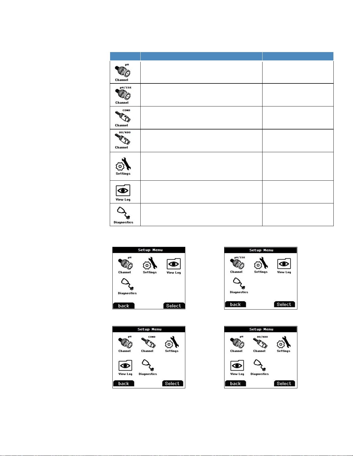
Main Setup Menu Icons and Descriptions
Icon
Description
Applicable Meter Models
Use the pH Channel menu to customize measurement,
mV), ORP and temperature
Star A211 pH meter
Star A215 pH/conductivity meter
Star A216 pH/RDO/DO meter
Use the pH/ISE Channel menu to customize
RmV (relative mV), ORP, ISE and temperature
Use the COND Channel menu to customize
conductivity, salinity, TDS, resistivity and temperature
Use the DO/RDO Channel menu to customize
dissolved oxygen and temperature
Use the Instrument Settings menu to update meter
shutoff, user ID and sample ID
Access the View Log menu to view, export or clear
recent calibrations per channel in the calibration log
Access the Diagnostics menu to initiate a meter reset,
the meter serial number and software revision
Star A211 pH Meter Setup Menu
Star A214 pH/ISE Meter Setup Menu
Star A215 pH/Conductivity Meter Setup Menu
Orion Star A216 pH/RDO/DO Meter Setup Menu
calibration and alarm settings for pH, mV, RmV (relative
Chapter 3 | Met er Set up Me nus
measurement, calibration and alarm settings for pH, mV,
measurement, calibration and alarm settings for
measurement, calibration and alarm settings for
settings for data transfer, data log, date and time,
language, sounds, stirrer speed, display contrast, auto-
saved data in the data log and view or print the ten most
perform a meter self test, test electrode stability or view
Example Main Setup Menu Displays
Star A214 pH/ISE meter
Star A212 conductivity meter
Star A215 pH/conductivity meter
Star A213 RDO/DO meter
Star A216 pH/RDO/DO meter
All Star A210 series meters
All Star A210 series meters
All Star A210 series meters
Thermo Scientific Orion Star A210 Series Benchtop Meter User Manual | 21
Page 22
Chapter 3 | Met er Set up Me nus
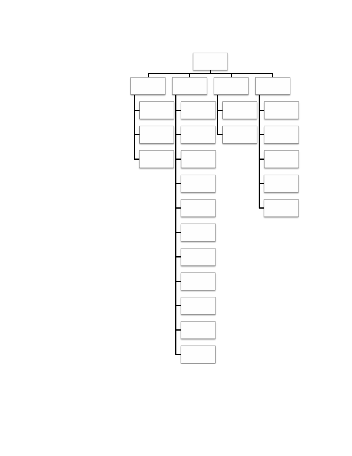
Main Setup Menu Flow Chart
Main Setup
Menu
Channel*
Method
Mode and
Settings
Temperature
Settings
Export Data
Data Log
Date / Time
Language
Key Press
Beep
Alarm Beep
View Log
Data Log
Calibration
Log
Diagnostics
Factory
Reset
User Reset
Self Test
Stability Test
About Meter
Stirrer
Contrast
Auto Shut
Off
User ID
Sample ID
* R
efer to next figure for a detailed list of the measurement, calibr ation and alarm setti ngs within
each channel-specific Mode and Settings menu.
22 | Orion Star A210 Series Benchtop Meter User Manual Thermo Scientific
Page 23

Channel-specific Mode and Settings Menu Flow Chart
Main Setup
Menu
Chapter 3 | Met er Set up Me nus
pH Channel
Mode and
Settings
Measure
Mode
Read Type
Resolution
Buffer
Group
Stability
Averaging
pH/ISE
Channel
Mode and
Settings
Measure
Mode
Read Type
Resolution
Buffer
Group
Measure
Unit
Blank
Correct
COND
Channel
Mode and
Settings
Measure
Mode
Read Type
Cell K
Type
(Salinity)
TDS Factor
Ref. Temp.
DO/RDO
Channel
Mode and
Settings
Measure
Mode
Measure
Unit
Resolution
Read Type
Baro
Pressure
Salinity
Correct
Limit Alarm
Cal Due
Alarm
Stability
Averaging
Limit Alarm
Cal Due
Alarm
Low Lv
Stability
Temp.
Comp.
Temp.
Coeff.
Stability
Averaging
Limit Alarm
Cal Due
Alarm
Cell Type
Stability
Averaging
Limit Alarm
Cal Due
Alarm
RDO Cap
Life
Thermo Scientific Orion Star A210 Series Benchtop Meter User Manual | 23
Page 24
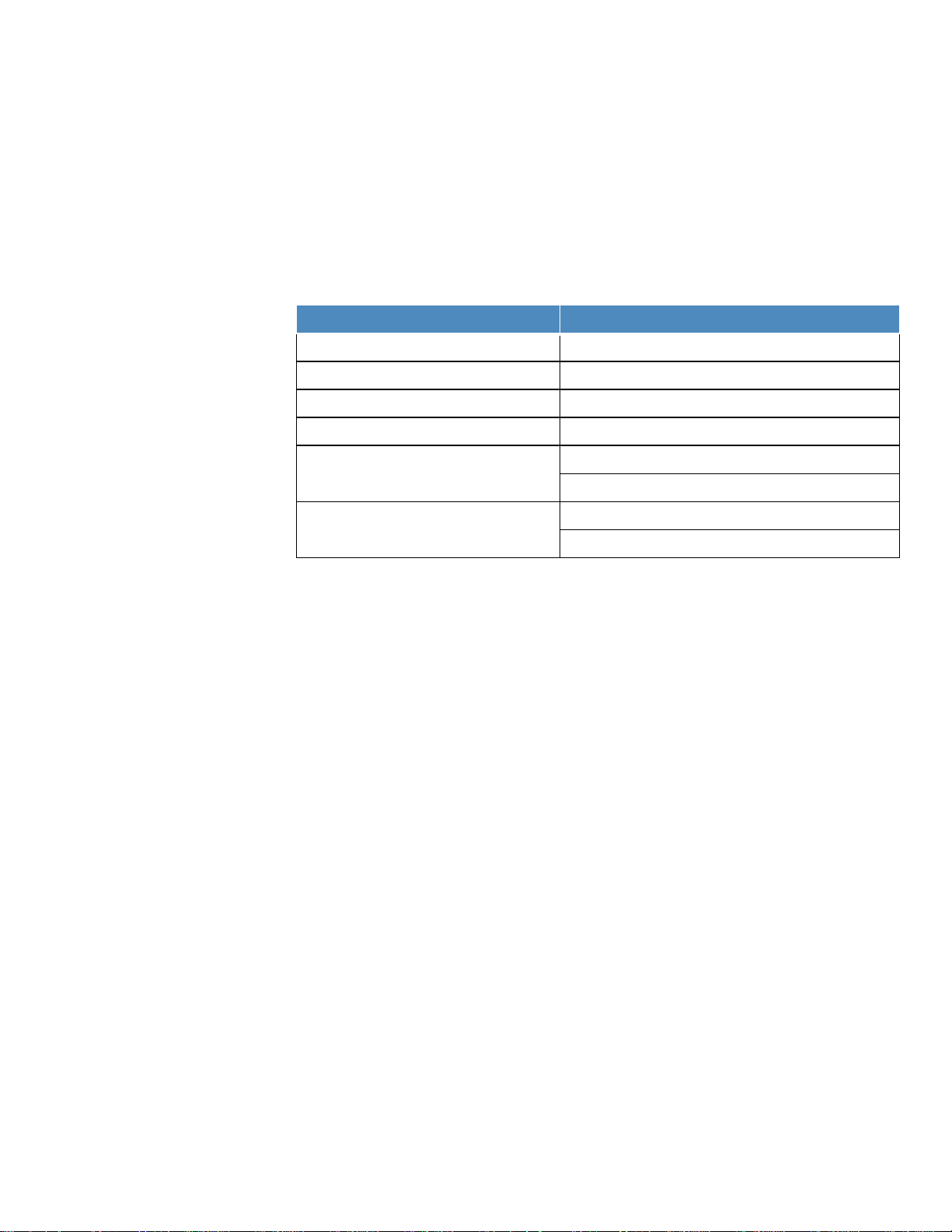
Chapter 3 | Met er Set up Me nus
Meter Model
Available Channel-specific Menus
Orion Star A211 pH meter
pH Channel
Orion Star A212 conductivity meter
COND Channel
Orion Star A213 RDO/DO meter
RDO/DO Channel
Orion Star A214 pH/ISE meter
pH/ISE Channel
pH Channel
COND Channel
pH Channel
RDO/DO Channel
Channel-Speci fic Method, Mode and Temperature Menus
Within the pH Channel, pH/ISE Channel, COND Channel and DO/RDO Channel menus are
Method, Mode and Settings and Temperature submenus, which can be used to customize the
measurement, calibration and alarm settings for each channel. The channel menus displayed
by each meter will depend on the meter model and its measuring capabilities.
Orion Star A215 pH/conductivity meter
Orion Star A216 meters pH/RDO/DO meter
• Method – Use the Method setup menu to create, load, copy, edit or delete password
protected methods.
• Mode and Settings – Select the Mode and Settings menu to review and update the
measurement, calibration and alarm settings for the selected channel.
• Temperature – Use the Temperature menu to manually enter a sample temperature value,
set the temperature units as °C or °F, perform a temperature calibration on an ATC probe
or conductivity / dissolved oxygen sensor with built-in temperature and set temperature
input source for meters with dual temperature sources.
24 | Orion Star A210 Series Benchtop Meter User Manual Thermo Scientific
Page 25

Chapter 3 | Met er Set up Me nus
0 1 2
.
3 4 5
6
7 8 9
–
back
done
enter
Method Menu
Save up to ten channel-specific methods in the Method menu for fast and easy recollection of
custom channel-specific measurement, calibration and alarm settings.
The default method (M100 or M200) is updated whenever the channel-specific measurement,
calibration and alarm settings are changed in the Mode and Settings menu and the default
method is not password protected.
The custom methods (M101-M110 or M201-M210) can be protected using a three to eight digit
password. When a protected method is created, loaded and active in the measurement mode
and a calibration is performed, that calibration will be saved to the method so every time the
method is loaded, the corresponding calibration will also be loaded.
Protected methods are helpful when using two or more electrodes on one channel. For
example, a pH electrode and an ion selective electrode (ISE) used on the same BNC input of
the Star A214 pH/ISE meter or a low range conductivity sensor and standard range conductivity
sensor used on the same 8 pin MiniDIN input of the Star A212 conductivity meter.
Creating a New Method using the Current Meter Set tings
1. In the measurement mode, press the setup key.
2. Press the p, q, t or u key to highlight pH Channel, pH/ISE Channel, COND Channel or
/RDO Channel
DO
3. Press the p or q key to highlight Method and press the f3 (select) key to access the
methods list.
4. Press the p or q key to highlight Current Settings and press the f3 (save) key.
5. Press the p or q key to highlight an open method (M101-M110 or M201-M210) to save
the current channel-specific settings to and press the f2 (accept) key.
a. Open methods have no date, time or mode shown in the methods list.
6. Use the popup number entry screen to create a method-specific password (3 to 8 digits).
a. Press the f3 (edit) key to access the number entry screen.
b. Press the p, q, t or u key to highlight a number, press th
f3
(enter) key to select the number and repeat until the desired
password is shown at the top of the number entry screen.
c. Press the f2 (done) key to accept the password and exit the
number entry screen.
7. Press the f2 (accept) key to save the entered password.
and press the f3 (select) key.
e
backspace
8. The meter will return to the methods list and the selected method number will have the date,
time and mode shown in the methods list.
Thermo Scientific Orion Star A210 Series Benchtop Meter User Manual | 25
Page 26

Chapter 3 | Met er Set up Me nus
Loading a Method
Use the load function to activate a protected method for use in the measurement mode. If no
protected method has been created, the open method is active. A password is not required to
load a protected method.
1. In the measurement mode, press the setup key.
2. Press the p, q, t or u key to highlight pH Channel, pH/ISE Channel, COND Channel or
O/RDO Channel
D
and press the f3 (select) key.
3. Press the p or q key to highlight Method and press the f3 (select) key to access the
methods list.
4. Press the p or q key to highlight a protected method to be loaded in the measurement
mode and press the f2 (load) key.
a. Protected methods have the date, time and mode shown in the methods list.
5. The meter will automatically proceed to the measurement mode.
Copying a Method
Use the copy function to save the channel-specific measurement, calibration and alarm settings
of an existing method to a new method, so the original method settings are preserved and the
new method settings can be modified. When using the copy function to create a new method, a
new password must be created for the new method to be saved.
1. In the measurement mode, press the setup key.
2. Press the p, q, t or u key to highlight pH Channel, pH/ISE Channel, COND Channel or
O/RDO Channel
D
and press the f3 (select) key.
3. Press the p or q key to highlight Method and press the f3 (select) key to access the
methods list.
4. Press the p or q key to highlight a protected method to be copied to an open protected
method and press the f3 (options) key.
a. Protected methods have the date, time and mode shown in the methods list.
5. Use the popup number entry screen to enter the specific password for the selected method.
a. Press the f3 (edit) key to access the number entry screen.
b. Press the p, q, t or u key to highlight a number, press the f3 (enter) key to select
the number and repeat until the correct password is shown at the top of the screen.
c. Press the f2 (done) key to accept the password and exit the number entry screen.
6. Press the f2 (accept) key to submit the password for the selected method.
7. Press the p or q key to highlight Copy and press the f2 (accept) key.
8. Press the p or q key to highlight an open method and press the f2 (accept) key.
a. Open methods have no date, time or mode shown in the methods list.
9. Use the popup number entry screen to create a password for the new method.
26 | Orion Star A210 Series Benchtop Meter User Manual Thermo Scientific
Page 27

Chapter 3 | Met er Set up Me nus
a. Press the f3 (edit) key to access the number entry screen.
b. Press the p, q, t or u key to highlight a number, press the f3 (enter) key to select
the number and repeat until the desired password is shown at the top of the screen.
c. Press the f2 (done) key to accept the password and exit the number entry screen.
10. Press the f2 (accept) key to submit the new password for the new method.
11. The meter will return to the methods list and the new method number will have the date,
time and mode shown in the methods list.
Editing or Deleti n g a Method
Use the edit function to modify the channel-specific measurement, calibration and alarm
settings of an existing protected method. Use the delete function to convert an existing
protected method to an open method.
1. In the measurement mode, press the setup key.
2. Press the p, q, t or u key to highlight pH Channel, pH/ISE Channel, COND Channel or
O/RDO Channel
D
and press the f3 (select) key.
3. Press the p or q key to highlight Method and press the f3 (select) key to access the
methods list.
4. Press the p or q key to highlight a protected method and press the f3 (options) key.
a. Protected methods have the date, time and mode shown in the methods list.
5. Use the popup number entry screen to enter the specific password for the selected method.
a. Press the f3 (edit) key to access the number entry screen.
b. Press the p, q, t or u key to highlight a number, press the f3 (enter) key to select
the number and repeat until the correct password is shown at the top of the screen.
c. Press the f2 (done) key to accept the password and exit the number entry screen.
6. Press the f2 (accept) key to submit the password for the selected method.
7. Press the p or q key to highlight Edit or Delete and press the f2 (accept) key.
a. If Edit is selected:
i. Perform the appropriate actions to set the channel-specific measurement,
alibration and alarm settings within the selected method.
c
ii. Once the required settings have been edited, press the f1 (back) key to retur
t
o the methods list.
b. If Delete is selected:
n
i. Press the f2 (yes) key to confirm the deletion of the selected method.
ii. The method will be deleted and the meter will automatically proceed to the
measurement mode.
Thermo Scientific Orion Star A210 Series Benchtop Meter User Manual | 27
Page 28

Chapter 3 | Met er Set up Me nus
Smart Stability Setting
mV per Minute
Stability Setting
mV per Minute
0.1 resolution or 1 significant digit
7.6
Fast Stability
7.6
0.01 resolution or 2 significant digits
2.9
Medium Stability
2.9
0.001 resolution or 3 significant digits
1.0
Slow Stability
1.0
Mode and Settings Menu
General Mode and Settings Options
Read Types
The read type determines how the meter displays, logs and exports measurements. Ensure the
appropriate data export and data log settings are enabled in the Instrument Settings menu
before logging or exporting measurements.
• Auto-Read:
o Press the measure (esc) key to start a measurement. The AR icon blinks as the
changing value stabilizes. When stable, the AR icon stops blinking and the
measurement is locked on the display until the measure (esc) key is pressed again.
o When enabled, the stable measurement is automatically saved to the data log an
d
exported to a printer or computer.
• Continuous
o M
:
easurement values are continuously updated on the display and the Stabilizing o
R
eady icon indicates the measurement stability status.
o When enabled, press the log/print key to save a measurement to the data log and
export it to a printer or computer.
• Timed
:
o M
easurement values are continuously updated on the display and the Stabilizing o
eady icon indicates the measurement stability status.
R
o When enabled, mea surements are saved to the data log and exported to a printer or
computer at the selected time interval of 3 seconds (00:00:03) to 24 hours
(24:00:00).
Stability Setting Information
The stability setting determines when a measurement is recognized as stable by the meter,
using an algorithm that evaluates measurement fluctuations. When Smart Stability is selected,
the measurement resolution is utilized in conjunction with the algorithm. Approximate mV per
minute values, estimated with ideal measurement conditions, are shown below. Values are
theoretical only and actual values will vary based on individual measurement conditions.
r
r
28 | Orion Star A210 Series Benchtop Meter User Manual Thermo Scientific
Page 29

Chapter 3 | Met er Set up Me nus
Averaging Setting
The averaging setting allows the operator to select Automatic Smart averaging for faster
measurement stability or Off for no measurement averaging once the stability criteria is met.
Limit Alarm Setting
The limit alarm setting allows measurements to be evaluated using set high limit and/or low limit
values. If a measurement goes above the high limit value or below the low limit value, the alarm
is triggered. For example, when the high limit is set to 8.50 pH, the alarm will activate when a
measurement of 8.51 pH or higher is read in the measurement mode. Turn on the alarm beep
setting in the Instrument Settings menu to enable an audible beep when the alarm is triggered.
Calibration Due Alarm Setting
The calibration due alarm allows the operator to set a custom calibration interval in hours. If a
calibration is not performed within the specified calibration interval, the alarm is triggered. Turn
on the alarm beep setting in the Instrument Settings menu to enab le an audible beep when the
alarm is triggered.
Thermo Scientific Orion Star A210 Series Benchtop Meter User Manual | 29
Page 30

Chapter 3 | Met er Set up Me nus
Parameter
Settings
Details
• pH
• ORP
• Auto
• Timed 00:00:03
Set the read type to determine how the meter takes a
the data log and/or external device
1 Decimal Place
3 Decimal Places
0.1
0.001
Set the buffer group for automatic buffer recognition
DIN: pH 1.68, 4.01, 6.86 and 9.18 buffers
• Smart Stability
• Slow
Set averaging for faster measurement stability,
conditions and optimizes the meter response time
• Limit Alarm
• Low Limit
Set the calibration due alarm off or on, when the cal
has elapsed without a calibration being performed
Mode and Settings Menu for pH Channel
Use the Mode and Settings menu to customize the measurement, calibration and alarm settings
for the pH channel of Orion Star A211 pH meters, Orion Star A215 pH/conductivity meters and
Orion Star A216 pH/RDO/DO meters. Default meter settings are bold.
Measure Mode
Read Type
Resolution
(pH only)
Buffer Group
(pH only)
Stability
Averaging
Limit Alarm
• mV
• RmV
• Continuous
2 Decimal Places
• USA
• DIN
• Fast
• Medium
• Off
• Autom atic Smart
Off On
• Alarm Settings
High High/Low Low
• High L imit
Set the displayed measurement mode, the selected
mode determines which additional settings are shown
and the type of calibration the meter will perform
measurement and when the measurement is sent to
0.01
Set the resolution of the pH measurement value
during pH calibrations
USA: pH 1.68, 4.01, 7.00, 10.01 and 12.46 buffers
Set when a measurement is recognized as stable,
Smart Stability compensates for measurement
conditions and optimizes the meter response time
Automatic Smart compensates for measurement
Set the limit alarm off or on, when alarm is on – set
the alarm setting as high, high/low or low and then
enter the appropriate measurement limit values
The limit alarm is triggered when the measurement
goes above the high limit or below the low limit
30 | Orion Star A210 Series Benchtop Meter User Manual Thermo Scientific
Cal Due Alarm
(pH, RmV and
ORP only)
• Cal Due Alarm
On Off
• Cal Due Limit
12 Hrs
due alarm is on – enter the calibration time interval in
hours (1 to 9998 hours)
The cal due alarm is triggered after the entered time
Page 31

Chapter 3 | Met er Set up Me nus
USA Buffer Set
DIN Buffer Set
pH Buffer
mV range
pH Buffer
mV range
1.68
+255 mV to +374 mV
1.68
+255 mV to +374 mV
4.01
+117 mV to +236 mV
4.01
+117 mV to +236 mV
7.00
-59 mV to +59 mV
6.86
-51 mV to +67 mV
10.01
-237 mV to -119 mV
9.18
-189 mV to -70 mV
12.46
-382 mV to -264 mV
Buffer Group Setting
Orion Star A211 pH meters, Orion Star A215 pH/conductivity meters and Orion Star A216
pH/RDO/DO meters are capable of automatically recognizing pH buffer values within the
selected buffer set during a pH calibration. During the pH calibration, the meter uses the
selected pH buffer set and the raw mV reading of the pH electrode in the buffer to recognize
and display the buffer value at the measured temperature. The raw mV reading of the pH
electrode in the buffer must be within one pH unit (approximately ±59 mV) of the buffer’s
theoretical mV value for the meter to recognize the buffer.
Testing a pH Electrode for Automatic Buffer Recognition
Use the following procedure to verify that the raw mV reading of the pH electrode is within one
pH unit (±59 mV) from the theoretical mV reading of the pH buffer, and therefore verify that the
pH electrode in use is capable of performing automatic buffer recognition.
1. Prepare the pH electrode according to the electrode manual. Set the meter measurement
mode to mV.
2. Rinse the pH electrode with distilled water, blot it dry with a lint-free tissue and place the pH
electrode into a pH 4.01 buffer at approximately 25 °C.
3. Wait for the measurement to stabilize and record the mV value of the pH 4.01 buffer when
the measurement is stable.
4. Remove the pH electrode from the pH 4.01 buffer.
5. Rinse the pH electrode with distilled water, blot it dry with a lint-free tissue and place the pH
electrode into a pH 7.00 buffer at approximately 25 °C.
6. Wait for the measurement to stabilize and record the mV value of the pH 7.00 buffer when
the measurement is stable.
7. The mV reading of the pH electrode in pH 4 buffer should be +117 to +236 mV and in pH
b
uffer should be -59 to +59 mV. If the mV readings are in the correct ranges, the pH
7
electrode is capable of performing automatic buffer recognition. If the mV readings are not
in the correct ranges, manually enter the pH buffer values during a pH calibration.
Thermo Scientific Orion Star A210 Series Benchtop Meter User Manual | 31
Page 32

Chapter 3 | Met er Set up Me nus
Parameter
Settings
Details
• pH
• RmV
Set the displayed measurement mode, the selected
and the type of calibration the meter will perform
• Auto
• Timed 00:00:03
Set the read type to determine how the meter takes a
1 Decimal Place
3 Decimal Places
0.1
0.001
Set the buffer group for automatic buffer recognition
DIN: pH 1.68, 4.01, 6.86 and 9.18 buffers
1 significant digit
3 significant digits
• ppm
• mg/L
• Percentage (%)
• None
Set the automatic blank correction function off or on
samples for improved measurement stability
• Smart Stability
• Slow
Set averaging for faster measurement stability,
conditions and optimizes the meter response time
• Limit Alarm
• Low Limit
Set the calibration due alarm off or on, when the cal
has elapsed without a calibration being performed
Set the low level stability function off or on for ISE
improve accuracy in low level calibration standards
Mode and Settings Menu for pH/ISE Chann el
Use the Mode and Settings menu to customize the measurement, calibration and alarm settings
for the pH/ISE channel of Orion Star A214 pH/ISE meters. Default meter settings are bold.
Measure Mode
Read Type
Resolution
(pH only)
Buffer Group
(pH only)
Resolution
(ISE only)
Measure Unit
(ISE only)
Blank Correct
(ISE only)
• mV
• ORP
• ISE
• Continuous
2 Decimal Places
• USA
• DIN
2 significant digits
• M
• ppb
• Yes
• No
mode determines which additional settings are shown
measurement and when the measurement is sent to
the data log and/or external device
0.01
Set the resolution of the pH measurement value
during pH calibrations
USA: pH 1.68, 4.01, 7.00, 10.01 and 12.46 buffers
Set the resolution of the ion concentration (ISE)
measurement value
Set the units displayed with the ion concentration
(ISE) measurement value
for ISE measurements, when the function is on – an
algorithm is used to compensate for the non-linear
response of the electrode in low level standards and
32 | Orion Star A210 Series Benchtop Meter User Manual Thermo Scientific
Stability
Averaging
Limit Alarm
Cal Due Alarm
(pH, RmV, ORP
and ISE only)
Low Lv Stability
• Fast
• Medium
• Off
• Autom atic Smart
Off On
• Alarm Settings
High High/Low Low
• High L imit
• Cal Due Alarm
On Off
• Cal Due Limit
12 Hrs
• Off
• On
Set when a measurement is recognized as stable,
Smart Stability compensates for measurement
conditions and optimizes the meter response time
Automatic Smart compensates for measurement
Set the limit alarm off or on, when alarm is on – set the
alarm setting as high, high/low or low and then enter
the appropriate measurement limit values
The limit alarm is triggered when the measurement
goes above the high limit or below the low limit
due alarm is on – enter the calibration time interval in
hours (1 to 9998 hours)
The cal due alarm is triggered after the entered time
calibrations, when the function is on – the minimum
stabilization time is increased (~3-5 minutes) to
Page 33

Chapter 3 | Met er Set up Me nus
Buffer Group Setting
Orion Star A214 pH/ISE meters are capable of automatically recognizing pH buffer values
within the selected buffer set during a pH calibration. During the pH calibration, the meter uses
the selected pH buffer set and the raw mV reading of the pH electrode in the buffer to recognize
and display the buffer value at the measured temperature. The raw mV reading of the pH
electrode in the buffer must be within one pH unit (approximately ±59 mV) of the buffer’s
theoretical mV value for the meter to recognize the buffer.
Blank Correct Setting
Orion Star A214 pH/ISE meters offer the option to use blank (non-linear) correction for ISE
measurements when a multi-point calibration is performed. The automatic blank correction
feature uses an algorithm to compensate for the non-linearity of an ion selective electrode in
low level standards and samples.
With the blank correction feature enabled, the meter decides whether blank correction is the
best measurement strategy by analyzing the electrode response during a multi-point calibration.
A separate blank does not have to be run. Graphically, blank correction is equivalent to drawing
a smooth curve through the lowest three points of the multi-point calibration and extrapolating to
zero concentration based on the assumption of Nernstian electrode behavior.
Multi-point calibrations at the lower limit of detection are desirable when the response of an ion
selective electrode is non-linear and cannot be characterized with a one or two point calibration.
This is usually seen as a low electrode slope. Generally, the electrode is behaving in a
Nernstian manner but the effect of a blank is being observed. See the figure below.
This blank may be a true reagent blank, traces of analate ion in the reagents or it may be the
“mud” value of the electrode. It could also be an interference in the reagents that becomes
apparent at low levels of analate ion, or it could be any combination of these effects. The
expanded version of the Nernst equation traditionally used for blank correction is as follows:
+ S * log (C + b) where b is the blank
E = E
0
Thermo Scientific Orion Star A210 Series Benchtop Meter User Manual | 33
Page 34

Chapter 3 | Met er Set up Me nus
In a multi-point calibration, a set of equations is generated and the relationship between them
evaluated. For example, the equations generated in a three point calibration would be:
= E0 + S * log (C1 + b)
E
1
E
= E0 + S * log (C2 + b)
2
E
= E0 + S * log (C3 + b)
3
The meter evaluates the relationships between the three potentials E
concentrations C
, C2 and C3. If the relationships indicate that blank correction is desired, a
1
, E2 and E3 and the three
1
blank will automatically be calculated and the non-linearity will be corrected for in a Nernstian
manner. If the appropriate conditions are not met, the blank is set at zero and each segment of
the multi-point calibration is treated independently.
When all three of the following conditions are met, blank correction is invoked.
1. The concentration of the first standard is zero, or the slope of the electrode between the first
and second standards is less than the slope between the second and third.
2. Potential differences between points are significant. For example, E
- E1 > 10 mV
3
3. The blank correction algorithm converges at reasonable blank and slope values. Conditions
in steps 1 and 2 prevent failure to converge in most situations. However, the slope will attain
any value necessary for convergence to a calculated blank value of 3 x C
.
3
When blank correction is implemented, the slope value for the electrode may be outside the
range of values normally considered acceptable during an ordinary calibration. For best results,
calibration standards should be close in range to the expect ed sample concentr ation s and
should bracket the expected sample concentration. When conditions 1, 2 and 3 are not met, the
calibration data is handled by the multi-point calibration method described earlier.
In calibrations with more than three points, a combination of methods is utilized. Automatic
blank correction is used if the lowest three points satisfy the criteria and multi-point calibration is
used for the other points. The slope calculated in the automatic blank correction algorithm and
the slopes for each additional segme nt are used to calculate the average slope.
Low Level Stability Setting
Orion Star A214 pH/ISE meters offer the option to use the low level stability feature when
calibrating ion selective electrodes. The low level stability feature improves the accuracy of low
concentration ISE measurements by adjusting the timing for calibration point s of low level
standards, allowing a longer stabilization time for the electrode in the calibration standards. The
stabilization time is typically extended to about three to five minutes per calibration point, but
will vary based on the actual readings from the electrode during calibration.
34 | Orion Star A210 Series Benchtop Meter User Manual Thermo Scientific
Page 35

Chapter 3 | Met er Set up Me nus
Parameter
Settings
Details
• Conductivity
• Resistivity
• Auto
• Timed 00:00:03
Set the read type to determine how the meter takes a
Enter the nominal cell constant (K) value of the
conductivity sensor for automatic conductivity calibration
Type
(Salinity only)
• Practical Salinity
• Sea Water
Set the type of salinity measurement as practical salinity
(psu) or natural sea water (ppt)
TDS Factor
(TDS only)
Enter the TDS factor value for total dissolved solids
measurements
• 5 °C
• 25°C
• Off
• EP
Enter the temperature coefficient used with the linear
temperature compensation setting
• Smart Stability
• Slow
Set averaging for faster measurement stability, Automatic
optimizes the meter response time
• Limit Alarm
Low Limit
• Cal Due Alarm
Set the calibration due alarm off or on, when on – enter
has elapsed without performing a calibration
• Standard
• USP
Set the type of conductivity senor as standard (most
sensors) or USP (2-cell sensors in ultra pure water)
Mode and Settings Menu for COND Channel
Use the Mode and Settings menu to customize the measurement, calibration and alarm settings
for the conductivity channel of Orion Star A212 condu ctiv ity meters and Orion Star A215
pH/conductivity meters. Default meter settings are bold.
Measure Mode
Read Type
• Salinity
• TDS
• Continuous
Cell K Cell K 0.4750
TDS Factor 0.49
• 10°C
Ref. Temp.
• 15°C
• 20°C
• Linear
Temp. Comp.
• nLFn
• nLFu
Set the displayed measurement mode, the selected mode
determines which additional settings are shown and the
type of calibration the meter will perform
measurement and when the measurement is sent to the
data log and/or external device
Set the reference temperature for temperature
compensated measurements, readings are adjusted to
the selected reference temperature when the temperature
compensation setting is active
Set the temperature compensation type as linear, nLFn
(non linear natural water), nLFu (non linear ultra pure
water), EP (compensation off with alarm when values are
outside EP requirements for ultra pure water) or off
Temp. Coeff. Temp. Coefficient 2.10
Stability
Averaging
Limit Alarm
Cal Due Alarm
(Conductivity
only)
Cell Type
Thermo Scientific Orion Star A210 Series Benchtop Meter User Manual | 35
• Fast
• Medium
• Off
• Autom atic Smart
Off On
• Alarm Settings
High High/Low Low
• High L imit
•
On Off
• Cal Due Limit
12 Hrs
Set when a measurement is recognized as stable, Smart
Stability compensates for measurement conditions and
optimizes the meter response time
Smart compensates for measurement conditions and
Set the limit alarm off or on, when alarm is on – set the
alarm setting as high, high/low or low and then enter the
appropriate measurement limit values
The limit alarm is triggered when the measurement goes
above the high limit or below the low limit
the calibration interval in hours (1 to 9998 hrs)
The calibration due alarm is triggered after the set time
Page 36

Chapter 3 | Meter Setup Menus
Catalog Number
Description
011008
Orion 100 μS conductivity standard, 5 x 60 mL
011007
Orion 1413 μS conductivity standard, 5 x 60 mL
01100710
Orion 1413 μS conductivity standard, 10 individual use pouches
011006
Orion 12.9 mS conductivity standard, 5 x 60 mL
01100610
Orion 12.9 mS conductivity standard, 10 individual use pouches
Cell K Setting
Orion Star A212 conductivity meters and Orion Star A215 pH/conductivity meters are capable
of automatically recognizing Thermo Scientific Orion 100 μS condu ctivity stand ard, 1413 μS
conductivity standard and 12.9 mS conductivity standard when the nominal cell constant (K)
value of the conductivity sensor is entered in the setup menu.
The nominal cell constant (K) values for Thermo Scientific Orion conductivity sensors
compatible with Star A210 series conductivity meters are listed below.
Catalog
Number
013005MD
013010MD
013020MD
013025MD
013605MD
013610MD
013016MD
011510MD
Description Measurement Range
Orion 4-cell conductivity/temperature sensor with
1.5 meter (5 foot) cable
Orion 4-cell conductivity/temperature sensor with
3 meter (10 foot) cable
Orion 4-cell conductivity/temperature sensor with
6 meter (20 foot) cable
Orion 4-cell conductivity/temperature sensor with
10 meter (32 foot) cable
Orion 4-cell conductivity/temperature sensor with
1.5 (5 foot)meter cable
Orion 4-cell conductivity/temperature sensor with
3 meter (10 foot) cable
Orion pure water 2-cell conductivity/temperature
sensor with 1.5 meter (5 foot) cable
Orion 2-cell conductivity/temperature sensor with
3 meter (10 foot) cable
1 μS/cm to 200 mS/cm 0.475 cm
1 μS/cm to 200 mS/cm 0.475 cm
1 μS/cm to 200 mS/cm 0.475 cm
1 μS/cm to 200 mS/cm 0.475 cm
10 μS/cm to 200 mS/cm 0.55 cm
10 μS/cm to 200 mS/cm 0.55 cm
0.01 μS/cm to 300 μS/cm 0.1 cm
10 μS/cm to 200 mS/cm 1.0 cm
Nominal Cell
Constant
-1
-1
-1
-1
-1
-1
-1
-1
011050MD
018020MD
36 | Orion Star A210 Series Benchtop Meter User Manual Thermo Scientific
Orion 2-cell conductivity/temperature sensor with
1.5 meter (5 foot) cable
Orion high range 2-cell conductivity sensor with
1.5 meter (5 foot) cable
1 μS/cm to 20 mS/cm 1.0 cm
10 μS/cm to 2000 mS/cm 10 cm
-1
-1
Page 37

Chapter 3 | Met er Set up Me nus
Solution (25 °C to 50 °C)
Temperature Coefficient (% / °C)
Sugar Syrup
5.64
Ultra Pure Water
4.55
98% Sulfuric Acid
2.84
Salt (NaCl)
2.12
Dilute Ammonia
1.88
5% NaOH
1.72
10% HCl
1.32
5% Sulfuric Acid
0.96
Reference Temperature, Temperature Compensation and Coefficient Settings
Orion Star A212 conductivity meters and Orion Star A215 pH/conductivity meters offer several
options for temperature compensated conductivity measurements. Temperature has a large
effect on the conductivity value of a solution. The temperature compensation feature allows the
meter to use the sample conductivity and temperature readings to calculate and display the
conductivity that the sample would be expected to have at a selected reference temperature,
such as 25 °C. To accurately use the temperature compensation feature, select the proper type
of temperature compensation for the samples to be measured; set the required reference
temperature as 5 °C, 10 °C, 15 °C, 20 °C or 25 °C; and use a conductivity sensor with built-in
ATC temperature probe. The options for temperature compensation are:
• Linear – uses the temperature coefficient value to apply a constant percent correctio
actor to every degree change in temperature. A few common linear coefficient values are:
f
n
• nLFn (non-linear ultra pure non-degassed water) – applies a non-constant correction factor
to pure water samples that have a varying response to changes in temperature. This mode
is for temperature compensated readings of low conductivity waters that are in equilibrium
with the carbon dioxide in air, such as pure waters reading near 1 μS/cm at 25 °C and
natural waters having a composition comparable to natural ground, well or surface waters.
• nLFu (non-linear ultra pure degassed water) – applies a non-constant correction factor to
pure water samples that have a varying response to changes in temperature. This mode is
for temperature compensated readings of ultra pure water that contains no air and no
carbon dioxide, such as ultra pure water (18 megohms resistance or higher) directly from
the source without aeration.
• EP – no temperature correction is applied (temperature compensation turned off) and a
warning is displayed if the measured conductivity value is over the EP requirement for pure
water at the measured sample temperature.
• Off - no temperature correction is applied and the actual conductivity value is displayed at
the measured sample temperature.
Thermo Scientific Orion Star A210 Series Benchtop Meter User Manual | 37
Page 38

Chapter 3 | Met er Set up Me nus
Salinity Type Setting
Orion Star A212 conductivity meters and Orion Star A215 pH/conductivity meters offer two
salinity types: practical salinity and natural sea water. Practical salinity measurements are
based on relating the sample measurement to the reading of a standard potassium chloride
(KCl) solution at 15 °C. Orion Star A210 series conductivity meters will automatically
temperature compensate and report the expected practical salinity result as practical salinity
units (psu) at 15 °C when using a conductivity sensor with built-in temperature. Natural sea
water measurements use a historic convention known as UNESCO 1966 and Orion Star A210
series conductivity meters will report the expected natural sea water result as parts per
thousand (ppt).
TDS Factor Setting
Orion Star A212 conductivity meters and Orion Star A215 pH/conductivity meters measure TDS
as the total amount of dissolved inorganic material in a solution. The dissolved inorganic
material carries a current that is measured by the conductivity sensor. Since there is a direct
relationship between conductivity and TDS, conductivity readings are used to estimate the
presence of inorganic material using the TDS factor entered in the setup menu.
The standard method of determining TDS involves evaporating a sample to dryness at 180 °C
and weighing the residue. The TDS factor is calculated by taking the residue weight and
dividing it by the sample conductivity. Subsequent conductivity readings are multiplied by the
TDS factor to determine the TDS value of the sample.
Cell Type Setting
Orion Star A212 conductivity meters and Orion Star A215 pH/conductivity meters accept 2-cell
and 4-cell conductivity sensors and allows the type of conductivity sensor to be set as Standard
(most conductivity sen sors) or USP (for the ultra pure water conductivity sensor, Catalog
Number 013016MD, when disabling temperature comp ensat ion).
38 | Orion Star A210 Series Benchtop Meter User Manual Thermo Scientific
Page 39

Chapter 3 | Met er Set up Me nus
Parameter
Settings
Details
Set the type of dissolved oxygen sensor connected to
and update the displayed measurement mode
• mg/L
% sat
Set the units displayed with the dissolved oxygen
measurement value
Resolution
(% saturation)
1 Decimal Place
2 Decimal Places
1
0.1
Set the resolution of the dissolved oxygen
measurement value as percent saturation
Resolution
(mg/L)
1 Decimal Place
2 Decimal Places
0.1
0.01
Set the resolution of the dissolved oxygen
measurement value as mg/L
• Auto
• Timed 00:00:03
Set the read type to determine how the meter takes a
Set the automatic barometric pressure compensation
entered barometric pressure value (Manual)
Enter the salinity value of samples for automatic
salinity correction of dissolved oxygen measurements
• Smart Stability
• Slow
Set averaging for faster measurement stability,
conditions and optimizes the meter response time
• Limit Alarm
• Low Limit
Set the limit alarm off or on, when the limit alarm is
entered low limit
Set the calibration due alarm off or on, when the cal
has elapsed without a calibration being performed
RDO Cap Life
(RDO only)
RDO Cap Life
0.0
View the remaining RDO optical DO sensor cap life in
Mode and Settings Menu for DO/RDO Channel
Use the Mode and Settings menu to customize the measurement, calibration and alarm settings
for the dissolved oxygen channel of Orion Star A213 RDO/DO meters and Orion Star A216
pH/RDO/DO meters. Default meter settings are bold.
Measure Mode
Measure Unit
Read Type
Baro Press
Salinity Correct
Stability
• DO – Polarographic
• RDO
• Auto
•
• Continuous
• Auto
• Manual 760.0mmHg
• Manual 0.0
• Fast
• Medium
the meter as DO polarographic or RDO optical or
select Auto and the meter will automatically detect
which type of dissolved oxygen sensor is connected
measurement and when the measurement is sent to
the data log and/or external device
source as the internal barometer (Auto) or a manually
Set when a measurement is recognized as stable,
Smart Stability compensates for measurement
conditions and optimizes the meter response time
Thermo Scientific Orion Star A210 Series Benchtop Meter User Manual | 39
Averaging
Limit Alarm
Cal Due Alarm
• Off
• Autom atic Smart
Off On
• Alarm Settings
High High/Low Low
• High L imit
• Cal Due Alarm
On Off
• Cal Due Limit
12 Hrs
Serial Number
Automatic Smart compensates for measurement
on – select the alarm settings as high, high/low or low
and then enter the measurement limit values
The limit alarm is triggered when a measurement
goes above the entered high limit or below the
due alarm is on – enter the calibration time interval in
hours (1 to 9998 hours)
The cal due alarm is triggered after the entered time
0
days and the serial number
Page 40

Chapter 3 | Met er Set up Me nus
Conductivity
(mS/cm)
Salinity
Value (ppt)
Conductivity
(mS/cm)
Salinity
Value (ppt)
Conductivity
(mS/cm)
Salinity
Value (ppt)
5 3 20
13
35
25 6 4
21
14
36
25 7 4
22
15
37
26 8 5
23
15
38
27 9 6
24
16
39
28
10 6 25
17
40
29
11 7 26
18
42
30
12 8 27
18
44
32
13 8 28
19
46
33
14 9 29
20
48
35
15
10
30
21
50
37
16
10
31
22
52
38
17
11
32
22
54
40
18
12
33
23
56
42
19
13
34
24
Barometric Pressure Compensation Setting
Orion Star A213 RDO/DO meters and Orion Star A216 pH/RDO/DO meters have an internal
barometer that can be used for automatic pressure compensated dissolved oxygen readings.
Manual entry of the barometric pressure can be used for automatic pressure compensated
dissolved oxygen readings, which is useful when dissolved oxygen is measured with a
submerged sensor or in a pressurized vessel. The pressure value must be entered as mm Hg.
1 mm Hg = 0.03937 inch Hg = 1.3332 hPa (mBar) = 0.01934 PSI
Salinity Correction Setting
Orion Star A213 RDO/DO meters and Orion Star A216 pH/RDO/DO meters are capable of
performing automatic salinity correction for dissolved oxygen readings (measured as mg/L)
when the salinity value of the sample is manually entered as ppt (parts per thousand) in the
setup menu.
at 20 °C
Correction
at 20 °C
Correction
at 20 °C
Correction
Calculated from the International Oceanographic Tables, Vol. 1, National Institute of
Oceanography of Great Britain, Womley, Godaming, Surrey, England and Unesco, Paris 1971
40 | Orion Star A210 Series Benchtop Meter User Manual Thermo Scientific
Page 41

Chapter 3 | Met er Set up Me nus
Meter Model
Channel
Temperature Menu
Menu Options
• Manual Temp Value
Enter temperature value
• Temperature Unit
• Celsius
• Fahrenheit
• Temperature Calibration
• ATC
• Manual Temp Value
Enter temperature value
• Temperature Unit
• Celsius
• Fahrenheit
• Temperature Calibration
• ATC
• Temperature Unit
• Celsius
• Solution Temperature
Sol & Mem Temp
• Manual Temp Value
Enter temperature value
• Temperature Unit
• Celsius
• Fahrenheit
• Temperature Calibration
• ATC
• Manual Temp Value
Enter temperature value
• Temperature Unit
• Celsius
• Fahrenheit
• Temperature Calibration
• ATC
• Manual Temp Value
Enter temperature value
• Temperature Unit
• Celsius
• Fahrenheit
• Temperature Calibration
• ATC
• Manual Temp Value
Enter temperature value
• Temperature Unit
• Celsius
• Fahrenheit
• ATC
• ATC, Sol & Mem Temp
• ATC
• DO Probe
• Temperature Unit
• Celsius
• Fahrenheit
• Solution Temperature
• Sol & Mem Temp
Temperature Menu
Orion Star A210 series benchtop meters offer a Temperature menu used to customize
temperature settings for each channel by manually entering a temperature value, selecting the
temperature units as °C or °F and performing a temperature calibration on an ATC probe,
conductivity sensor or dissolved oxygen sensor with built-in temperature. Orion Star A216
pH/RDO/DO meters also have the option to use one temperature input source for both
measurement channels.
Star A211 pH Meter pH Channel
Star A212
Conductivity Meter
Star A213 RDO/DO
Meter
Star A214 pH/ISE
Meter
Star A215 pH/
Conductivity Meter
COND
Channel
DO/RDO
Channel
pH/ISE
Channel
pH Channel
COND
Channel
• Temperature Calibration
(polarographic DO sensor only)
• Membrane T emperature
•
Thermo Scientific Orion Star A210 Series Benchtop Meter User Manual | 41
Star A216 pH/RDO/DO
Meter
pH Channel
DO/RDO
Channel
• Temperature Calibration
• Temperature Input
• Temperature Calibration
(polarographic DO sensor only)
• Solution Temperature
• Membrane T emperature
• Sol & Mem Temperature
• Manual
• Membrane T emperature
Page 42

Chapter 3 | Met er Set up Me nus
0 1 2 . 3 4 5 6 7 8 9
–
backspace
back
done
enter
Manual Temperature Value
1. In the measurement mode, press the setup key.
2. Press the p, q, t or u key to highlight pH Channel, pH/ISE Channel or COND Channel
nd press the f3 (select) key.
a
3. Press the p or q key to highlight Temperature and press the f3 (select) key.
4. Press the p or q key to highlight Manual Temp Value and press the f3 (select) key.
5. Press the f3 (edit) key access the popup number entry screen and enter the sample
temperature value
. Press the p, q, t or u key to highlight a number, decimal point
a
or negative sign and then press the f3 (enter) key to select the
highlighted item. Repeat until the sample temperature v alue is
shown at the top of the screen.
b. Press the f2 (done) key to save the value and exit the number
entry screen.
6. Press the f1 (back) key to return to the main temperature menu and press the measure
(esc) key to return to the measurement mode.
.
Temperature U n it
1. In the measurement mode, press the setup key.
2. Press the p, q, t or u key to highlight pH Channel, pH/ISE Channel, COND Channel or
O/RDO Channel
D
3. Press the p or q key to highlight Temperature and press the f3 (select) key.
4. Press the p or q key to highlight Temperature Unit and press the f3 (select) key.
5. Press the p or q key to highlight Celsius or Fahrenheit and press the f3 (select) key.
6. Press the measure (esc) key to return to the measurement mode .
and press the f3 (select) key.
42 | Orion Star A210 Series Benchtop Meter User Manual Thermo Scientific
Page 43

Chapter 3 | Met er Set up Me nus
Temperature C alibration
When using Orion Star A210 series benchtop meters, a temperature calibration can be
performed on an ATC probe, conductivity sensor with built-in temperat ur e or polarographic
dissolved oxygen sensor with built-in temperature when the probe or sensor is connected t o the
meter. Use the temperature calibration function only when necessary, since the meter has a
relative temperature accuracy of ±0.1°C and ATC probes have varying accu racies, usua lly
±0.5°C to ±2°C. Since the temperature offset calculated during the calibration is applied to all
future temperature measurements, recalibrate the temperature if a different ATC probe is used.
1. In the measurement mode, press the setup key.
2. Press the p, q, t or u key to highlight pH Channel, pH/ISE Channel, COND Channel or
O/RDO Channel
D
3. Press the p or q key to highlight Temperature and press the f3 (select) key.
4. Press the p or q key to highlight Temperature Calibration and press the f3 (select) key.
5. Press the p or q key to highlight ATC and press the f3 (select) key.
a. If using the Star A213 meter, press the p or q key to highlight Solution Temperature,
embrane Temperature
M
and press the f3 (select) key.
or Sol & Mem Temperature and press the f3 (select) key.
b. If using the Star A216 meter, press the p or q key to highlight ATC, Solution
Temperature, Membrane Temperature, Sol & Mem Temperature or ATC, Sol & Mem
Temp and press the f3 (select) key.
6. Place the ATC probe and/or sensor into a solution with a known, stable temperature. Two
NIST-traceable thermometers should be used to measure and verify the temperature.
7. Wait for the temperature value on the meter to stabilize and then press the f3 (edit) key t
a
ccess the popup number entry screen and enter the temperature value
a
. Press the p, q, t or u key to highlight a number, decimal point or negative sign and
.
o
then press the f3 (enter) key to select the highlighted item. Repeat until the desired
temperature value is shown at the top of the screen.
b. Press the f2 (done) key to exit the number entry screen.
8. Press the f2 (accept) key to save the entered temperature value.
9. Press the f1 (meas) key to return to the measurement mode.
Temperature Calibration for Meters with Multiple Temperature I nputs
When a polarographic dissolved oxygen sensor with two temperature inputs is connected with
an Orion Star A213 RDO/DO meter or Orion Star A216 pH/RDO/DO meter, the solution
temperature input and membrane temperature input can be calibrated separately or together.
When an ATC probe and polarographic dissolved oxygen sensor are both connected to the
Orion Star A216 pH/RDO/DO meter, the temperature calibration for both inputs can also be
performed together.
Thermo Scientific Orion Star A210 Series Benchtop Meter User Manual | 43
Page 44

Chapter 3 | Met er Set up Me nus
Temperature Input
When using the Orion Star A216 pH/RDO/DO meter, a dissolved oxygen sensor with built-in
temperature can be set as the temperature input source for all measurements. For example,
when using a pH electrode without an ATC probe, the dissolved oxygen sensor with built-in
temperature can be used as the temperature source for pH measurements, as long as both the
pH electrode and dissolved oxygen sensor are placed in the same solution.
1. In the measurement mode, press the setup key.
2. Press the p, q, t or u key to highlight pH Channel and press the f3 (select) key.
3. Press the p or q key to highlight Temperature and press the f3 (select) key.
4. Press the p or q key to highlight Temperature Input and press the f3 (select) key.
5. Press the p or q key to highlight ATC, DO Probe or Manual and press the f3 (select) key.
6. Press the measure (esc) key to return to the measurement mode .
44 | Orion Star A210 Series Benchtop Meter User Manual Thermo Scientific
Page 45

Chapter 3 | Met er Set up Me nus
Instrument
Setting
• Printing
4800 38400
Access the data export menu to set data transfer
• Off
• On
Turn data logging on to save measurement data to the
data log according to the selected read type
• Date
Time: 14:30
• English
•
(Chinese)
• Off
• On
Turn the audible beep on or off each time a meter key
is pressed
• Off
• On
Turn the audible beep on or off when an alarm is
triggered
Adjust the display contrast higher or lower to improve
display viewing in different light conditions
• Off
On
Turn on function to automatically power off the meter
when no keys are pressed for 20 minutes
Enter a user ID value (up to six characters) using the
alphanumeric entry screen
• Off
• Auto Increment
Set sample ID as off, manual (up to six alphanumeric
are automatically increased for each measurement)
Instrument Sett ings Setup Menu
Use the Instrument Settings menu to update meter settings for data transfer, data log, date and
time, language, sounds, stirrer speed, display contrast, auto-shutoff, user ID and sample ID.
Options Details
Export Data
Data Log
Date and Time
Language
Off On
• Comm Setup
RS232 USB
• Data Format
Printer PC (CSV)
• Comm Config
1200 9600
2400 19200
DD/MM/YY
MM/DD/YY
Date: 01/01/12
• Time
12 Hour Clock
Time: 02:30 PM
24 Hour Clock
• Español
• Deutsch
• Français
• Italiano
中文
settings for exporting measurement and calibration
information to a printer or computer
Turn printing on to allow data transfer from the meter to
an external device, select the data transfer format as
printer (standard text) or PC (comma delimited text)
and set the meter baud rate to match the printer or
computer baud rate
The meter will automatically detect when an RS232 or
USB cable is connected to a meter port
Use the date setting to select the date format as
day/month/year (DD/MM/YY) or month/day/year
(MM/DD/YY) and then enter the month, day and year
values
Use the time setting to set the time format as 12 hour
clock or 24 hour clock and then enter the hour and
minute values
Set the language to be used for the meter interface,
additional languages (including Portuguese and
Korean) are available with software updates on our
website at
www.thermoscientific.com/OrionMeters
Key Press Beep
Alarm Beep
Stirrer
Contrast
Auto Shut Off
User ID ABCDE
Thermo Scientific Orion Star A210 Series Benchtop Meter User Manual | 45
Sample ID
•
• Manual
A
djust the stirrer speed setting from one (slowest) to
five (fastest) when using an Orion Star stirrer probe
characters) or auto incremental (up to six numbers that
Page 46

Chapter 3 | Met er Set up Me nus
Log View Menu
Use the Log View menu to access the data log and calibration log. All information in the data
and calibration logs is protected by the meter’s nonvolatile memory, so stored information is
saved in the meter even when it is not connected to a power supply.
Data Log
Orion Star A210 series benchtop meters offer a 2000 point data log. Each point includes the
actively displayed measurements, depending on the meter model and display configuration,
with date and time stamp. When the data log function is turned on, the read type selected for
each displayed channel (Auto-Read, Continuous or Timed) determines how the point is saved
to the data log.
1. In the measurement mode, press the setup key.
2. Press the p, q, t or u key to highlight View Log and press the f3 (select) key.
3. Press the p or q key to highlight Data Log and press the f2 (select) key.
4. The meter will display a list of the data log points. The list shows the sequential number of
the points and the data and time the point was saved.
5. To view measurement information for an individual point:
a. Press the p or q key to highlight a point and then press the f2 (select) key.
b. Press the f1 (back) key to return to the list of data log points.
6. To export the data log to a printer or computer:
a. Press the f3 (options) key, press the p or q key to highlight Log Export and then
press the f2 (accept) key.
b. Press the p or q key to highlight Today, Last 10, Range or All and then press the f2
(accept) key.
i. If Range is selected, press the p or q key to highlight the number of the first
) and last (to) points to be exported, use the popup number entry screen
rom
(f
to edit the numbers and press the f2 (accept) key to save the entered range.
c. Press the f2 (yes) key to confirm that the meter is interfaced with a printer or computer.
The meter will automatically return to the data log list once the export is completed.
7. To clear the data log memory:
a. Press the f3 (options) key, press the p or q key to highlight Log Clear and then
press the f2 (accept) key.
b. Press the f2 (yes) key to confirm erasing the entire data log from the meter’s memory.
c. Press the f3 (edit) key, use the popup number entry screen to enter the default meter
password of 111111 and then press the f2 (done) key.
d. Press the f2 (accept) key and wait for the data log to be cleared.
46 | Orion Star A210 Series Benchtop Meter User Manual Thermo Scientific
Page 47

Chapter 3 | Met er Set up Me nus
Exported Calibration Log Example,
Calibration Log
Orion Star A210 series meters save up to ten of the most recent calibrations per channel.
1. In the measurement mode, press the setup key.
2. Press the p, q, t or u key to highlight View Log and press the f3 (select) key.
3. Press the p or q key to highlight Calibration Log and press the f2 (select) key.
4. Press the p or q key to highlight pH–Channel, pH/ISE–Channel, Conductivity–Channel or
DO/RDO–Channel
a. If pH–Channel is selected, press the p or q key to highlight pH, RmV or ORP and
press the f2 (select) key.
b. If pH/ISE–Channel is selected, press the p or q key to highlight pH, RmV, ORP or
and press the f2 (select) key.
SE
I
c. If Conductivity–Channel is selected, press the p or q key to highlight Conductivity,
esistivity
R
d. If DO/RDO–Channel is selected, press the p or q key to highlight DO or RDO and
press the f2 (select) key.
and press the f2 (select) key.
, TDS or Salinity and press the f2 (select) key.
Printer Data Format:
5. The meter will display a list of calibrations for the selected channel and calibration mode.
The list chows the sequential number of the calibration log and the data and time the
calibration was completed.
6. To view detailed information for an individual calibration, press the p or q key to highlight
a calibration and then press the f2 (select) key.
a. To export the calibration to a printer or computer, press the f2 (print) key.
Thermo Scientific Orion Star A210 Series Benchtop Meter User Manual | 47
Page 48

Chapter 3 | Met er Set up Me nus
Diagnostics Menu
Use the Diagnostics Menu to initiate a meter reset, test electrode stability, perform a meter self
test or view meter and module serial numbers and software revisions.
• Factory Reset – All meter settings are reset to factory defaults. Data log, calibration log and
methods are deleted. Use the default meter password of 111111 to complete the reset.
• User Reset – All channel-specific measurement, calibration and alarm settings as well a
a
ll instrument settings are reset to factory defaults and methods are erased. Data log and
calibration log are retained.
• Self Test – Tests the meter accuracy. A self test is also performed automatically by the
meter at each power up.
• Stability Test – Tests the stability of an electrode by measuring the raw input reading per
minute drift and noise.
• About Meter – Displays the meter model, serial number and software revision.
Meter Self Test Procedure
1. In the measurement mode, press the setup key.
2. Press the p, q, t or u key to highlight Diagnostics and press the f3 (select) key.
3. Press the p or q key to highlight Self Test and press the f2 (select) key.
4. Disconnect all electrodes and sensors from the meter, attach the BNC shorting cap to the
BNC input if applicable and press the f2 (yes) key.
5. Press the f2 (yes) key to start the self test.
6. The meter will perform the self test. Once Self Test Passed is displayed, press the f1 (esc)
key and the meter will automatically proceed to the measurement mode.
s
Meter Verification Pro cedure (pH and pH/ISE Channels Only)
1. After completing the self test, the meter will return to the measurement mode. Keep all of
the electrodes and sensors disconnected from the meter and keep the BNC shorting cap
attached to the BNC input on the meter.
2. Set the measurement mode to pH. The meter should read a steady 7.000 pH ±0.002 pH.
a. If the meter does not read a steady 7.000 ±0.002, perform a one point pH calibration
with the BNC shorting cap attached to the BNC input. Set the pH value to 7.000 and the
slope value to 100.0. Refer to the pH Calibration section for detailed instructions.
3. Set the measurement mode to mV. The meter should read a steady 0.0 mV ±0.2 mV
a
. If the meter does not read a steady 0.0 mV ±0.2 mV with the BNC shorting ca
attached to the BNC input, contact Technical Support.
48 | Orion Star A210 Series Benchtop Meter User Manual Thermo Scientific
.
p
Page 49

Chapter 3 | Met er Set up Me nus
Electrode Stability Test Procedure
1. In the measurement mode, press the setup key.
2. Press the p, q, t or u key to highlight Diagnostics and press the f3 (select) key.
3. Press the p or q key to highlight Stability Test and press the f2 (select) key.
4. Press the p or q key to highlight pH–Channel, pH/ISE–Channel, Conductivity–Channel or
DO/RDO–Channel
5. Make sure the electrode or sensor to be tested is connected to the channel selected in the
previous step and press the f2 (yes) key.
6. Place the electrode or sensor in an appropriate solution with a stable temperature and press
the f2 (yes) key.
a. Thermo Scientific Orion pH 7.00 buffer (Catalog Number 910107, 910760 or 910710) is
recommended for testing a pH electrode.
b. Thermo Scientific Orion ORP standard (Catalog Number 967901 or 967961) is
recommended for testing an ORP electrode.
c. A calibration standard with a moderate concentration of the ion of interest is
recommended for testing an ion selective electrode (ISE).
and press the f2 (next) key.
d. Thermo Scientific Orion 1413 µS conductivity standard (Catalog Number 011007 or
01100710) is recommended for testing most conductivity sensors. Thermo Scientific
Orion 100 µS conductivity standard (Catalog Number 011008) is recommended for
testing ultra pure water conductivity sensors.
e. A prepared water-saturated air calibration sleeve is recommended for testing RDO
optical and polarographic dissolved oxygen sensors.
7. The meter will perform the stability test and show the raw input reading per minute drift and
noise on the display.
8. The meter will display Stability Test Passed or Stabi lity T est F ailed. Press the f1 (esc) key
o return to the measurement mode.
t
Thermo Scientific Orion Star A210 Series Benchtop Meter User Manual | 49
Page 50

4
CHAPTER 4
Using the pH or pH/ISE Channel
Use the Orion Star A211 pH meter, Orion Star A215 pH/conductivity meter or Orion Star A216
pH/RDO/DO meter to measure pH, mV, relative mV, ORP and temperature. Use the Orion Star
A214 pH/ISE meter to measure pH, ion concentration using an ISE (ion selective electrode),
mV, relative mV, ORP and temperature. The following chapter provides instructions on
connecting electrodes, calibrating the system and measuring these parameters.
Meter and Electrode Preparation
1. Familiarize yourself with general meter operation and prepare the meter and accessories
according to the instructions in
a. It is recommended that electrodes be placed in the meter-attached electrode stand for
easy movement in and out of containers during calibration, measur ement and storage .
Chapter 2 Meter Basics.
2. Refer to the instructions in
calibration and alarm settings within the pH Channel or pH/ISE Channel setup menu and
data transfer, data log, date and time, language, sounds, stirrer speed, display contras
uto-shutoff, user ID and sample ID settings within the Instrument Settings setup menu.
a
3. Connect all necessary electrodes, probes and sensors to the appropriate meter inputs.
a. Connect a pH, ORP or ion selective electrode to the BNC meter input.
b. Connect an ATC temperature probe to the 8 pin MiniDIN meter input.
c. Connect a reference half-cell electrode to the pin tip meter input (for use when a half-
cell sensing electrode with BNC connector is used).
d. Connect the stirrer probe (Catalog Number 096019) to the Stirrer meter input.
4. Prepare all connected electrodes for use as instructed in the electrode manuals.
50 | Orion Star A210 Series Benchtop Meter User Manual Thermo Scientific
Chapter 3 Meter Setup Menus to customize measurement,
t,
Page 51

Chapter 4 | Using the pH or pH/ISE Chann el
pH Calibration Procedure
Orion Star A211 pH meters, Orion Star A214 pH/ISE meters, Orion Star A215 pH/conductivity
meters and Orion Star A216 pH/RDO/DO meters can perform a pH calibration using one to five
pH buffers with easy to follow onscreen instructions to assist with the calibration process.
Always use fresh pH buffers and select buffers that bracket the sample pH and are one to three
pH units apart. Prepare the pH electrode according to the instructions in the electrode manual.
Connect all electrodes to be used to the appropriate meter inputs.
Make sure the meter measurement mode is set to pH. For Star A215 and Star A216 meters,
press the f3 (channel) key until the pH channel is shown in the measurement mode.
5. Press the f1 (cal) key to start the calibration.
a. If more than one channel is displayed in the measurement mode, press the p or q
key to highlight pH-Channel
6. Rinse the pH electrode and any other electrodes in use with distilled water, blot gently with
lint-free tissue to remove excess water and place into the pH buffer.
a
and press the f2 (select) key.
7. When the electrode and buffer are ready, press the f3 (start) key.
a. If using a stirrer probe, the stirrer probe will start stirring when the f3 (start) ke
p
ressed and stop stirring when the reading stabilizes.
8. Wait for the pH value on the meter to stabilize and perform one of the following actions:
a. Press the f2 (accept) key to accept the pH buffer value determined by the automatic
buffer recognition function.
or
b. Press the f3 (edit) key to access the popup number entry screen and manually enter
the pH buffer value.
i. Press the p, q, t or u key to highlight a number or decimal point, press th
f3 (enter) key to select the highlighted item and repeat until the desired value is
shown at the top of the screen.
ii. Press the f2 (done) key to save the value and exit the number entry screen.
iii. Press the f2 (accept) key to accept the manually entered value.
9. Press the f2 (next) key to proceed to the next pH buffer and repeat steps 2 through 4 or
press the f3 (cal done) key to save and end the calibration. If five buffers are used, the
calibration will save and end once the fifth value is accepted.
a. When performing a one point calibration, press the f2 (accept) key to accept th
d
isplayed slope value or press the f3 (edit) key, use the popup number entry screen to
enter a new slope value, press the f2 (done) key and then press the f2 (accept) key.
y is
e
e
10. The meter will display the calibration summary including the slope and export the data to the
calibration log. Press the f1 (meas) key to proceed to the measurement mode or press the
f2 (print) key to export the calibration data to a printer or computer.
Thermo Scientific Orion Star A210 Series Benchtop Meter User Manual | 51
Page 52

Chapter 4 | Using the pH or pH/ISE Chann el
pH Calibration Editing
When the calibration summary is displayed, the calibration editing option can be selected to fix
individual points without having to perform a full recalibration.
1. In the calibration summary display (after step 5 in the pH Calibration Procedure), press the
f3 (cal edit) key.
2. Press the p or q key to highlight a calibration point to edit and press the f2 (select) key.
3. Press the p or q key to highlight Remeasure, Edit or Delete and press the f2 (select) key.
a. If Remeasure is selected, repeat steps 2 through 4 in the pH Calibration Procedure.
b. If Edit is selected, press the f3 (edit) key, use the popup number entry screen to enter
a new pH buffer value, press the f2 (done) key and then press the f2 (accept) key.
Select another calibration point to edit or press the f1 (back) key.
c. If Delete is selected, the calibration point will be deleted. If deleting the point changes it
to a one point calibration, enter the slope using the popup number entry screen.
4. The meter will display an updated calibration summary and export the data to the calibratio
l
og. Press the f1 (meas) key to proceed to the measurement mode or press the f2 (print)
key to export the calibration data to a printer or computer.
n
52 | Orion Star A210 Series Benchtop Meter User Manual Thermo Scientific
Page 53

Chapter 4 | Using the pH or pH/ISE Chann el
ORP Calibration P r ocedure (Relativ e m V Mode)
Orion Star A211 pH meters, Orion Star A214 pH/ISE meters, Orion Star A215 pH/conductivity
meters and Orion Star A216 pH/RDO/DO meters can perform an ORP calibration in the relative
mV (RmV) mode using one standard with easy to follow onscreen instructions to assist with the
calibration process.
Use the Thermo Scientific Orion ORP standard (Catalog Number 967901 or 967961) or other
ORP standard as desired. Prepare the electrode according to the instructions in the electrode
manual. Connect all electrodes to be used to the appropriate meter inputs.
Make sure the meter measurement mode is set to RmV. For Star A215 and Star A216 meters,
press the f3 (channel) key until the RmV channel is shown in the measurement mode.
1. Press the f1 (cal) key to start the calibration.
a. If more than one channel is displayed in the measurement mode, press the p or q
key to highlight pH-Channel
and press the f2 (select) key.
2. Rinse the electrode and any other electrodes in use with distilled water, blot gently with a
t-free tissue to remove excess water and place into the standard.
lin
3. When the electrode and standard are ready, press the f3 (start) key.
a. If using a stirrer probe, the stirrer probe will start stirring when the f3 (start) ke
p
ressed and stop stirring when the reading stabilizes.
4. Wait for the mV value on the meter to stabilize (indicated by the flashing stabilizing or solid
ready icon) and perform one of the following actions:
a. Press the f2 (accept) key to accept the mV value.
or
b. Press the f3 (edit) key to access the popup number entry screen and manua lly enter
the mV value expected at the measured temperature.
i. Press the p, q, t or u key to highlight a number, decimal point or negative
sign; press the f3 (enter) key to select the highlighted item and repeat unti l the
desired value is shown at the top of the screen.
ii. Press the f2 (done) key to save the value and exit the number entry scree n.
iii. Press the f2 (accept) key to accept the manually entered value.
5. The meter will display the calibration summary including the mV offset and export the data
to the calibration log. Press the f1 (meas) key to proceed to the measurement mode o
ress the f2 (print) key to export the calibration data to a printer or computer.
p
y is
r
Thermo Scientific Orion Star A210 Series Benchtop Meter User Manual | 53
Page 54

Chapter 4 | Using the pH or pH/ISE Chann el
ORP Calibration Procedure (EH Units)
Orion Star A211 pH meters, Orion Star A214 pH/ISE meters, Orion Star A215 pH/conductivity
meters and Orion Star A216 pH/RDO/DO meters can perform a one point automatic ORP
calibration to the E
when using the following items:
• Thermo Scientific Orion ORP standard (Catalog Number 967901 or 967961)
• Thermo Scientific Orion ORP electrode (Catalog Number 9678BNWP, 9778BNWP,
9180BNMD or 9179BNMD)
• Thermo Scientific Orion 4 M KCl filling solution (Catalog Number 900011) or 4 M KCl gel
(in the 9179BNMD electrode)
Orion ORP standard is nonhazardous, stable and will not change over time, so it is an ideal
standard for any ORP measurement system. Always use fresh ORP standard. Prepare the
ORP electrode according to the instructions in the electrode manual. Connect all electrodes to
be used to the appropriate meter inputs.
value (relative to the Standard Hydrogen Electrode, 420 mV at 25 °C)
H
Make sure the meter measurement mode is set to ORP. For Star A215 and Star A216 meters,
press the f3 (channel) key until the ORP channel is shown in the measurement mode.
1. Press the f1 (cal) key to start the calibration.
a. If more than one channel is displayed in the measurement mode, press the p or q
key to highlight pH-Channel
and press the f2 (select) key.
2. Rinse the electrode and any other electrodes in use with distilled water, blot gently with a
lint-free tissue to remove excess water and place into the standard.
3. When the electrode and standard are ready, press the f3 (start) key.
a. If using a stirrer probe, the stirrer probe will start stirring when the f3 (start) ke
p
ressed and stop stirring when the reading stabilizes.
y is
4. Wait for the mV value on the meter to stabilize (indicated by the flashing stabilizing or solid
ready icon) and press the f2 (accept) key once the mV value is stable.
5. The meter will display the calibration summary including the mV offset and export the data
to the calibration log. Press the f1 (meas) key to proceed to the measurement mode o
r
press the f2 (print) key to export the calibration data to a printer or computer.
54 | Orion Star A210 Series Benchtop Meter User Manual Thermo Scientific
Page 55

Chapter 4 | Using the pH or pH/ISE Chann el
ISE Calibration Procedure
Orion Star A214 pH/ISE meters can perform an ion concentration calibration using one to five
standards with easy to follow onscreen instructions to assist with the calibration process.
Always use fresh standards and select standards that bracket the sample concentration and are
one decade (ten times) apart in concentration. To accurately prepare calibration standards from
a stock solution, serial dilution is recommended using calibrated pipettes. If ISA will be added to
samples, the same ISA must be added to all standards prior to calibration to ensure a
consistent dilution factor. If more than one standard is used for calibration, start with the lowest
concentration standard and work up to the highest concentration standard last.
Prepare the ion selective electrode according to the instructions in the electrode manual.
Connect all electrodes to be used to the appropriate meter inputs. Make sure the meter
measurement mode is set to ISE.
1. Press the f1 (cal) key to start the calibration.
2. Rinse the ion selective electrode and any other electrodes in use with distilled water, blot
gently with a lint-free tissue to remove excess water and place into the standard.
3. When the electrode and standard are ready, press the f3 (start) key.
a. If using a stirrer probe, the stirrer probe will start stirring when the f3 (start) ke
p
ressed and stop stirring when the reading stabilizes.
4. Wait for the value on the meter to stabilize and perform one of the following actions:
a. Press the f2 (accept) key to accept the displ ayed con centrat ion value.
or
b. Press the f3 (edit) key to access the popup number entry screen and manua lly enter
the concentration value.
i. Press the p, q, t or u key to highlight a number or decimal point, press th
f3
(enter) key to select the highlighted item and repeat until the desired value is
shown at the top of the screen.
ii. Press the f2 (done) key to save the value and exit the number entry screen.
iii. Press the f2 (accept) key to accept the manually entered value.
5. Press the f2 (next) key to proceed to the next standard and repeat steps 2 through 4 or
press the f3 (cal done) key to save and end the calibration. If five standards are used, the
calibration will save and end once the fifth value is accepted.
y is
e
a. When performing a one point calibration, press the f2 (accept) key to accept the
displayed slope value or press the f3 (edit) key, use the popup number entry screen to
enter a new slope value, press the f2 (done) key and then press the f2 (accept) key.
6. The meter will display the calibration summary including the slope and export the data to the
calibration log. Press the f1 (meas) key to proceed to the measurement mode or press the
f2 (print) key to export the calibration data to a printer or computer.
Thermo Scientific Orion Star A210 Series Benchtop Meter User Manual | 55
Page 56

Chapter 4 | Using the pH or pH/ISE Chann el
ISE Calibration Editing
When the calibration summary is displayed, the calibration editing option can be selected to fix
individual points without having to perform a full recalibration.
1. In the calibration summary display (after step 5 in the ISE Calibration Procedure), press the
f3 (cal edit) key.
2. Press the p or q key to highlight a calibration point to edit and press the f2 (select) key.
3. Press the p or q key to highlight Remeasure, Edit or Delete and press the f2 (select) key.
a. If Remeasure is selected, repeat steps 2 through 4 in the ISE Calibration Procedure.
b. If Edit is selected, press the f3 (edit) key, use the popup number entry screen to enter
a new standard value, press the f2 (done) key and then press the f2 (accept) key.
Select another calibration point to edit or press the f1 (back) key.
c. If Delete is selected, the calibration point will be deleted. If deleting the point changes it
to a one point calibration, enter the slope using the popup number entry screen.
4. The meter will display an updated calibration summary and export the data to the calibratio
l
og. Press the f1 (meas) key to proceed to the measurement mode or press the f2 (print)
key to export the calibration data to a printer or computer.
n
56 | Orion Star A210 Series Benchtop Meter User Manual Thermo Scientific
Page 57

Chapter 4 | Using the pH or pH/ISE Chann el
Measurement Proced ure
Prepare the electrodes according to the instructions in the electrode manuals. Connect all
electrodes to be used to the appropriate meter inputs. Make sure the electrodes are recently
calibrated and working correctly.
Ensure the meter measurement mode is set to the desired measurement parameter. For Orion
Star A215 and Orion Star A216 meters, press the f3 (channel) key until the desired channel or
channels are shown in the measurement mode.
1. Rinse the electrodes with distilled water or appropriate solution, blot gentl y with a lint-free
tissue to remove excess water and place into the sample.
2. Start the measurement and wait for the reading to stabilize or reach the predefined time.
a. Auto-Read: Press the measure (esc) key to start the measurement. If using a stirrer
probe, the stirrer probe will start stirring when the measure (esc) key is pressed and
stop stirring when the measurement stabilizes.
b. Continuous: Measurements will start immediately when in the measurement mode. If
sing a stirrer probe, press the stirrer key to start and stop stirring.
u
c. Timed: Measurements will start immediately when in the measurement mode. If using a
stirrer probe, press the stirrer key to start and stop stirring.
3. Once the measurement is stable or reaches the set time, record all applicable parameters.
a. Auto-Read: Once the measurement is stable, it will be locked and held on the display
and the AR icon will remain solid. If the data log function is enabled, the measurement
will be exported to the data log.
b. Continuous: The flashing Stabilizing icon will update to the solid Ready icon when th
measurement is stable. If the data log function is enabled, press the log/print key to
xport the measurement to the data log.
e
c. Timed: Measurements will be recorded at the predefined time interval. If the data log
function is enabled, the < icon will be shown when each time interval has elapsed and
the measurement is exported to the data log.
4. Remove the electrodes from the sample, rinse with distilled water or appropriate solu tion
b
lot gently with a lint-free tissue to remove excess water and place into the next sample.
5. Repeat steps 2 through 4 for all samples. When all samples have been measured, store the
electrodes according to the instructions in the electrode manuals.
,
e
Thermo Scientific Orion Star A210 Series Benchtop Meter User Manual | 57
Page 58

5
CHAPTER 5
Using the Conductivity Channel
Use the Orion Star A212 cond uctivity meter or Orion Star A215 pH/conductivity meter to
measure conductivity, salinity, TDS, resistivity and temperature. The following chapter provides
instructions on connecting sensors, calibrating the system and measuring these parameters.
Meter and Sensor Preparation
1. Familiarize yourself with general meter operation and prepare the meter and accessories
according to the instructions in
a. It is recommended that sensors be placed in the meter-attached electrode stand for
easy movement in and out of containers during calibration, measurement and storage.
Chapter 2 Meter Basics.
2. Refer to the instructions in
calibration and alarm settings within the COND Channel setup menu and data transfer, data
log, date and time, language, sounds, stirrer speed, display contrast, auto-shutoff, user ID
and sample ID settings within the Instrument Settings setup menu.
3. Connect all necessary electrodes, probes and sensors to the appropriate meter inputs.
a. Connect a conductivity sensor to the 8 pin MiniDIN meter input. If the conductivit
s
ensor has built-in temperature, the temperature will also be measured when the
conductivity sensor is connected with the meter.
b. Connect the stirrer probe (Catalog Number 096019) to the Stirrer meter input.
4. Prepare all connected sensors for use as instructed in the sensor manuals.
58 | Orion Star A210 Series Benchtop Meter User Manual Thermo Scientific
Chapter 3 Meter Setup Menus to customize measurement,
y
Page 59

Chapter 5 | Using the Conductivity Cha n nel
Conductivity Cal ibration Procedure
Orion Star A212 conductivity meters and Orion Star A215 pH/conductivity meters can perform a
conductivity calibration using one to five conductivity standards with easy to follow onscreen
instructions to assist with the calibration process or by the manual entry of the certified
conductivity cell consta nt (K) v alue.
Always use fresh standards and select standards that are near the expected sample
conductivity. Prepare the conductivity sensor according to the instructions in the sensor manual.
Connect all sensors to be used to the appropriate meter inputs.
Make sure the meter measurement mode is set to conductivity (Cond). For Star A215 meters,
press the f3 (channel) key until the conductivity channel is shown in the measurement mode.
Note: For an automatic calibration, enter the nominal cell constant of the conductivity sens o r in
the channel-specific setup menu and use Orion 100 μS, 1413 μS and/or 12.9 mS standards.
1. Press the f1 (cal) key to start the calibration.
a. If more than one channel is displayed in the measurement mode, press the p or q
key to highlight Conductivity-Channel
2. Rinse the conductivity sensor and any other electrodes in use with distilled water, blot gently
with a lint-free tissue to remove excess water and place into the conductivity standard.
3. When the sensor and standard are ready, press the f3 (start) key.
a. If using a stirrer probe, the stirrer probe will start stirring when the f3 (start) ke
p
ressed and stop stirring when the reading stabilizes.
4. Wait for the value on the meter to stabilize and perform one of the following actions:
a. Press the f2 (accept) key to accept the conductivity value d etermin ed by automati c
standard recognition function (Orion 100 μS, 1413 μS and 12.9 mS standards only).
or
b. Press the f3 (edit) key to access the popup number entry screen and manua lly enter
the conductivity standard value expected at the measured temperature.
i. Press the p, q, t or u key to highlight a number or decimal point, press th
f3 (enter) key to select the highlighted item and repeat until the desired value is
shown at the top of the screen.
ii. Press the f2 (done) key to save the value and exit the number entry screen.
iii. Press the f2 (accept) key to accept the manually entered value.
and press the f2 (select) key.
y is
e
5. Press the f2 (next) key to proceed to the next standard and repeat steps 2 through 4 or
press the f3 (cal done) key to save and end the calibration. If five standard are used, the
calibration will save and end once the fifth value is accepted.
6. The meter will display the calibration summary and export the data to the calibration log.
Press the f1 (meas) key to proceed to the measurement mode or press the f2 (print) key t
export the calibration data to a printer or computer.
Thermo Scientific Orion Star A210 Series Benchtop Meter User Manual | 59
o
Page 60

Chapter 5 | Using the Cond uctivity Channel
Conductivity Calibration Editing
When the calibration summary is displayed, the calibration editing option can be selected to fix
individual points without having to perform a full recalibration.
1. In the calibration summary display (after step 5 in the Conductivity Calibration Procedure),
press the f3 (cal edit) key.
2. Press the p or q key to highlight a calibration point to edit and press the f2 (select) key.
3. Press the p or q key to highlight Remeasure, Edit or Delete and press the f2 (select) key.
a. If Remeasure is selected, repeat steps 2 through 4 in the Calibration Procedure.
b. If Edit is selected, press the f3 (edit) key, use the popup number entry screen to enter
a new conductivity standard value, press the f2 (done) key and then press the f
(
accept) key. Select another calibration point to edit or press the f1 (back) key.
c. If Delete is selected, the calibration point will be deleted.
2
4. The meter will display an updated calibration summary and export the data to the calibratio
og. Press the f1 (meas) key to proceed to the measurement mode or press the f2 (print)
l
key to export the calibration data to a printer or computer.
Alternative Certified Cell Constant Entry Calibration Procedure
When using the cell constant entry calibration procedure, enter the certified cell constant (K)
value that is printed on the conductivity sensor cable or certificate of calibration.
1. Press the f1 (cal) key to start the calibration.
a. If more than one channel is displayed in the measurement mode, press the p or q
key to highlight Conductivity-Channel
2. Press the f2 (cell K) key.
3. Wait for the conductivity value on the meter to stabilize and then press the f3 (edit) key to
access the popup number entry screen and enter the certified cell constant value.
a. Press the p, q, t or u key to highlight a number or decimal point, press the f3
(enter) key to select the highlighted item and repeat until the desired value is shown at
the top of the screen.
b. Press the f2 (done) key to save the value and exit the number entry screen.
c. Press the f2 (accept) key to accept the entered cell constant value.
and press the f2 (select) key.
n
4. Press the f2 (accept) key to save and end the calibration and export the data to the
calibration log. The meter will automatically proceed to the measurement mode .
5. The conductivity measurement system is now calibrated. Verify the calibration by reading a
known conductivity standard or according to your SOP.
60 | Orion Star A210 Series Benchtop Meter User Manual Thermo Scientific
Page 61

Chapter 5 | Using the Cond uctivity Channel
Temperature
Orion 111.9mS
Orion 12.9mS
Orion 1413μS
Orion 147μS
Orion 100μS
0
65.10
7.135
776
81
54
1
66.84
7.344
799
83
56 2 68.59
7.555
822
86
58 3 70.35
7.768
846
88
59 4 72.12
7.983
870
91
61 5 73.91
8.200
894
93
63
6
75.70
8.418
918
96
64
7
77.50
8.638
943
98
66 8 79.32
8.860
968
101
68 9 81.15
9.084
992
103
70
10
82.98
9.309
1017
106
72
11
84.83
9.535
1043
108
73
12
86.69
9.763
1068
111
75
13
88.56
9.993
1094
114
77
14
90.45
10.22
1119
116
79
15
92.34
10.46
1145
119
81
16
94.24
10.69
1171
122
83
17
96.15
10.93
1198
125
85
18
98.08
11.16
1224
127
87
19
100.0
11.40
1251
130
88
20
102.0
11.64
1277
133
90
21
103.9
11.88
1304
136
92
22
105.9
12.12
1331
138
94
23
107.9
12.36
1358
141
96
24
109.9
12.61
1386
144
98
25
111.9
12.85
1413
147
100
26
113.9
13.10
1441
150
102
27
115.9
13.35
1468
153
104
28
117.9
13.59
1496
156
106
29
120.0
13.84
1524
159
108
30
122.0
14.09
1552
161
110
31
124.1
14.34
1580
164
112
32
126.2
14.59
1608
167
114
33
128.3
14.85
1636
170
117
34
130.4
15.10
1665
173
119
35
132.5
15.35
1693
176
121
36
134.6
15.61
1722
179
123
37
136.7
15.86
1751
182
125
38
138.9
16.12
1780
185
127
39
141.0
16.37
1808
188
129
40
143.2
16.63
1837
191
131
41
145.4
16.89
1866
194
134
42
147.6
17.15
1896
197
136
43
149.8
17.40
1925
200
138
44
152.0
17.66
1954
203
140
45
154.2
17.92
1983
206
142
46
156.4
18.18
2013
209
145
47
158.7
18.44
2042
212
147
48
160.9
18.70
2071
215
149
49
163.2
18.96
2101
219
151
50
165.4
19.22
2130
222
154
Conductivity Standards vs. Temperat ure Table
(°C)
Standard (mS/cm)
Standard (mS/cm)
Standard (μS/cm)
Standard (μS/cm)
Standard (μS/cm)
Thermo Scientific Orion Star A210 Series Benchtop Meter User Manual | 61
Page 62

Chapter 5 | Using the Cond uctivity Channel
Resistor Number
Nominal Resistance
Nominal Conductance
Nominal Acceptance Range
1010001-A
1000 KΩ
1 μS
0.984 to 1.016 μS
1010001-B
100 KΩ
10 μS
9.930 to 10.07 μS
1010001-C
10 KΩ
100 μS
99.30 to 100.7 μS
1010001-D
1 KΩ
1000 μS
993.0 to 1007 μS
1010001-E
100 Ω
10 mS
9.930 to 10.07 mS
1010001-F
10 Ω
100 mS
99.30 to 100.7 mS
Conductivity Meter Verification Procedure
Use the Orion Star series conductivity meter verification kit, Catalog Number 10100 01, to verify
the accuracy of the conductivity measurements on Orion Star A212 conductivity meters and
Orion Star A215 pH/conductivity meters. The measured conductivity value of each resistor
should fall within the relative accuracy of the resistor (±0.1% of the actual resistor conductance)
plus the relative accuracy of the meter (±0.5% of reading ±1 digit for readings greater than 3
μS/cm or ±0.5% of reading ±0.01μS/cm for readings less than or equal to 3 μS/cm).
1. Ensure that the conductivity resistor kit is cer tif ie d and has a valid calibration date.
2. In the measurement mode, press the f1 (cal) key.
a. If more than one channel is displayed in the measurement mode, press the p or q
key to highlight Conductivity-Channel
3. Press the f2 (cell K) key.
4. Press the f3 (edit) key to access the popup number entry screen and enter a cell constant
value of 1.0000.
and press the f2 (select) key.
a. Press the p, q, t or u key to highlight a number or decimal point, press the f3
(enter) key to select the highlighted item and repeat until the desired value is shown at
the top of the screen.
b. Press the f2 (done) key to save the value and exit the number entry screen.
c. Press the f2 (accept) key to accept the entered cell constant value.
5. The meter will automatically proceed to the measurement mode and Cell Constant: 1.0000
ill be shown on the display.
w
6. Connect a resistor to the meter, press the measure (esc) key to start the measurement,
wait for the measurement value to stabilize and then record the displayed condu ct iv ity valu e
of the resistor
7
. Repeat step 6 for all six resist ors in the kit.
.
62 | Orion Star A210 Series Benchtop Meter User Manual Thermo Scientific
Note: These are the nominal values for the resistors only. The actual resistance and
conductance is printed on each resistor and the actual acceptance range must be calculated
from the actual value on each resistor.
Page 63

Chapter 5 | Using the Cond uctivity Channel
Measurement Proced ure
Prepare the sensors according to the instructions in the sensors manuals. Connect all
electrodes, sensors and probes to be used to the appropriate meter inputs. Make sure the
sensors are recently calibrated and working correctly.
Ensure the meter measurement mode is set to the desired measurement parameter. For Star
A215 meters, press the f3 (channel) key until the desired channel or channels are shown in the
measurement mode.
1. Rinse the sensors with distilled water or appropriate solution, blot gently with a lint-free
tissue to remove excess water and place into the sample.
2. Start the measurement and wait for the reading to stabilize or reach the predefined time.
a. Auto-Read: Press the measure (esc) key to start the measurement. If using a stirrer
probe, the stirrer probe will start stirring when the measure (esc) key is pressed and
stop stirring when the measurement stabilizes.
b. Continuous: Measurements will start immediately when in the measurement mode. If
sing a stirrer probe, press the stirrer key to start and stop stirring.
u
c. Timed: Measurements will start immediately when in the measurement mode. If using a
stirrer probe, press the stirrer key to start and stop stirring.
3. Once the measurement is stable or reaches the set time, record all applicable parameters.
a. Auto-Read: Once the measurement is stable, it will be locked and held on the display
and the AR icon will remain solid. If the data log function is enabled, the measurement
will be exported to the data log.
b. Continuous: The flashing Stabilizing icon will update to the solid Ready icon when th
measurement is stable. If the data log function is enabled, press the log/print key to
xport the measurement to the data log.
e
c. Timed: Measurements will be recorded at the predefined time interval. If the data log
function is enabled, the < icon will be shown when each time interval has elapsed and
the measurement is exported to the data log.
4. Remove the sensors from the sampl e, rinse with distilled water or appropriate solution, blot
gently with a lint-free tissue to remove excess water and place into the next sample.
5. Repeat steps 2 through 4 for all samples. When all samples have been measured, store the
sensors according to the instructions in the sensor manuals.
e
Thermo Scientific Orion Star A210 Series Benchtop Meter User Manual | 63
Page 64

6
CHAPTER 6
Using the DO/RDO Channel
Use the Orion Star A213 RDO/DO meter or Orion Star A216 pH/RDO/DO meter to measure
dissolved oxygen as percent saturation or mg/L and temperatur e using either Orion RDO
optical or polarographic dissolved oxygen sensors. The following chapter provides instructions
on connecting sensors, calibrating the system and measuring these parameters.
Meter and Sensor Preparation
1. Familiarize yourself with general meter operation and prepare the meter and accessories
according to the instructions in
a. It is recommended that sensors be placed in the meter-attached electrode stand for
easy movement in and out of containers during calibration, measurement and storage.
Chapter 2 Meter Basics.
2. Refer to the instructions in
calibration and alarm settings within the DO/RDO Channel setup menu and data transfer
d
ata log, date and time, language, sounds, stirrer speed, display contrast, auto-shutoff, user
ID and sample ID settings within the Instrument Settings setup menu.
3. Connect all necessary electrodes, probes and sensors to the appropriate meter inputs.
a. Connect an RDO optical or polarographic dissolved oxygen sensor to the 9 pin MiniDIN
meter input. The meter will automatically detect which dissolved oxygen sensor i
connected. The temperature will also be measured when the dissolved oxygen sensor
is connected with the meter.
b. Connect the stirrer probe (Catalog Number 096019) to the Stirrer meter input.
4. Prepare all connected sensors for use as instructed in the sensor manuals.
64 | Orion Star A210 Series Benchtop Meter User Manual Thermo Scientific
Chapter 3 Meter Setup Menus to customize measurement,
,
s
Page 65

Chapter 6 | Using the DO/R D O Channel
Dissolved Oxygen Calibration Procedure
Note: A polarographic dissolved oxygen sensor must be polarized prior to use. The
polarographic dissolved oxygen sensor is continuously polarized when connected to the meter.
If the polarographic dissolved oxygen sensor is new, has been serviced or has not been
connected to the meter – connect the sensor to the meter, power on the meter and wait 30
minutes for the sensor to polarize.
Orion Star A213 RDO/DO meters and Orion Star A216 pH/RDO/DO meters can perform the
following calibrations:
• Air (water-saturated air) – This is the simplest and most accurate method and uses the
calibration sleeve included with most dissolved oxygen sensors. For best accuracy, the
calibration temperature should match the expected sample temperature. Moisten the
sponge in the calibration sleeve with distilled water and insert the sensor into the sleeve.
Alternatively, a BOD bottle can be used with just enough distilled water to cover the bottom
without touching the sensor
.
• Water (air-saturated water) – This method uses water that is 100% saturated with air.
Bubble air into a water sample for an extended period, preferably overnight.
• Manual (Winkler) – This method uses a water sample with a known concentration of
dissolved oxygen and is typically used to calibrate the DO sensor to the value achieved by
a Winkler titration. Due to possible titration errors, this method is inherently less accurate.
• Set Zero – This method uses an oxygen free solution to add a zero point to an existin
Water Saturated Air or Air Saturated Water calibration. This calibr at ion is gen eral ly
ecommended when measurements are below 10% saturation or 1 mg/L.
r
Prepare the dissolved oxygen sensor according to the instructions in the sensor manual.
Connect all sensors to be used to the appropriate meter inputs.
Make sure the meter measurement mode is set to dissolved oxygen (DO or RDO). For Star
A216 meters, press the f3 (channel) key until the dissolved oxygen channel is shown in the
measurement mode.
g
Thermo Scientific Orion Star A210 Series Benchtop Meter User Manual | 65
Page 66

Chapter 6 | Using the DO/R D O Channel
Air (Water-saturated Air) Calibration
1. Press the f1 (cal) key to start the calibration.
a. If more than one channel is displayed in the measurement mode, press the p or q
key to highlight DO/RDO-Channel
2. Press the p or q key to highlight Air and press the f3 (select) key.
3. Prepare the DO sensor and calibration sleeve and allow them to reach equilibrium.
4. When the DO sensor and calibration sleeve are ready, press the f3 (start) key.
5. Wait for the dissolved oxygen value on the meter to stabilize.
a. With a polarographic DO sensor, 102.3% will be displayed when the reading stabilizes.
b. With an RDO optical DO sensor, 100.0% will be displayed when the reading stabilizes.
6. Press the f2 (cal done) key to save and end the calibration.
7. The meter will display the calibration summary and export the data to the calibration log.
Press the f1 (meas) key to proceed to the measurement mode or press the f2 (print) key t
e
xport the calibration data to a printer or computer.
and press the f2 (select) key.
o
Water (Air-saturated Water) Calibration
1. Press the f1 (cal) key to start the calibration.
a. If more than one channel is displayed in the measurement mode, press the p or q
key to highlight DO/RDO-Channel
2. Press the p or q key to highlight Water and press the f3 (select) key.
3. Prepare the DO sensor and 100% air-saturated water and allow them to reach equilibrium.
a. Use plastic paraffin film to seal the open area between the DO sensor and vessel
ontaining the 100% air-saturated water
c
. When the DO sensor and calibration apparatus are ready, press the f3 (start) key.
4
a. If using a stirrer probe, the stirrer probe will start stirring when the f3 (start) ke
p
ressed and stop stirring when the reading stabilizes.
5. Wait for the dissolved oxygen value on the meter to stabilize.
a. 100.0% will be displayed when the reading stabilizes.
6. Press the f2 (cal done) key to save and end the calibration.
7. The meter will display the calibration summary and export the data to the calibration log.
Press the f1 (meas) key to proceed to the measurement mode or press the f2 (print) key t
e
xport the calibration data to a printer or computer.
and press the f2 (select) key.
.
y is
o
66 | Orion Star A210 Series Benchtop Meter User Manual Thermo Scientific
Page 67

Chapter 6 | Using the DO/R D O Channel
Manual (Winkler) Calibration
1. Press the f1 (cal) key to start the calibration.
a. If more than one channel is displayed in the measurement mode, press the p or q
key to highlight DO/RDO-Channel
2. Press the p or q key to highlight Manual and press the f3 (select) key.
3. Prepare the DO sensor and calibration solution and allow them to reach equilibrium.
a. Use plastic paraffin film to seal the open area between the DO sensor and vessel
ontaining the calibration solut ion.
c
4. When the DO sensor and calibration apparatus are ready, press the f3 (start) key.
and press the f2 (select) key.
a. If using a stirrer probe, the stirrer probe will start stirring when the f3 (start) ke
p
ressed and stop stirring when the reading stabilizes.
y is
5. Wait for the dissolved oxygen value on the meter to stabilize and perform one of the following
actions:
a. Press the f2 (accept) key to accept the displ ayed dis solved oxyge n value.
Or
b. Press the f3 (edit) key to access the popup number entry screen and manua lly enter
the dissolved oxygen value.
i. Press the p, q, t or u key to highlight a number or decimal point, press th
f3 (enter) key to select the highlighted item and repeat until the desired value is
shown at the top of the screen.
ii. Press the f2 (done) key to save the value and exit the number entry screen.
6. Press the f2 (cal done) key to save and end the calibration.
7. The meter will display the calibration summary and export the data to the calibration log.
Press the f1 (meas) key to proceed to the measurement mode or press the f2 (print) key t
xport the calibration data to a printer or computer.
e
e
o
Thermo Scientific Orion Star A210 Series Benchtop Meter User Manual | 67
Page 68

Chapter 6 | Using the DO/RDO Channel
Set Zero Calibration
An Air (water-saturated air) calibration or Water (air-saturated water) calibration must be
completed before a Set Zero calibration can be performed.
Prepare a sodium sulfite solution by dissolving about 15.0 grams of Na
in about 250 mL of
2SO3
distilled water. Transfer the solution to a BOD bottle or f las k and use plastic paraffin film to seal
the bottle. A small amount of cobalt salt can be added to the sodium sulfite solution to act as an
indicator and change color when the sodium sulfite solution no longer has zero oxygen content.
1. Press the f1 (cal) key to start the calibration.
a. If more than one channel is displayed in the measurement mode, press the p or q
key to highlight DO/RDO-Channel
and press the f2 (select) key.
2. Press the p or q key to highlight Set Zero and press the f3 (select) key.
3. Prepare the DO sensor and zero oxygen solution and allow them to reach equilibrium.
a. Use plastic paraffin film to seal the open area between the DO sensor and vessel
ontaining the calibration solut ion.
c
4. When the DO sensor and calibration apparatus are ready, press the f3 (start) key.
a. If using a stirrer probe, the stirrer probe will start stirring when the f3 (start) ke
p
ressed and stop stirring when the reading stabilizes.
y is
5. Wait for the dissolved oxygen value on the meter to stabilize.
a. 0.0% will be displayed for P2 when the reading stabilizes.
6. Press the f2 (cal done) key to save and end the calibration.
7. The meter will display the calibration summary and export the data to the calibration log.
Press the f1 (meas) key to proceed to the measurement mode or press the f2 (print) key t
e
xport the calibration data to a printer or computer.
o
68 | Orion Star A210 Series Benchtop Meter User Manual Thermo Scientific
Page 69

Chapter 6 | Using the DO/R D O Channel
Measurement Proced ure
Prepare the sensors according to the instructions in the sensors manuals. Connect all
electrodes, sensors and probes to be used to the appropriate meter inputs. Make sure the
sensors are recently calibrated and working correctly.
Ensure the meter measurement mode is set to the desired measurement parameter. For Star
A216 meters, press the f3 (channel) key until the desired channel or chan nels are shown in the
measurement mode.
1. Rinse the sensors with distilled water or appropriate solution, blot gently with a lint-free
tissue to remove excess water and place into the sample.
2. Start the measurement and wait for the reading to stabilize or reach the predefined time.
a. Auto-Read: Press the measure (esc) key to start the measurement. If using a stirrer
probe, the stirrer probe will start stirring when the measure (esc) key is pressed and
stop stirring when the measurement stabilizes.
b. Continuous: Measurements will start immediately when in the measurement mode. If
sing a stirrer probe, press the stirrer key to start and stop stirring.
u
c. Timed: Measurements will start immediately when in the measurement mode. If using a
stirrer probe, press the stirrer key to start and stop stirring.
3. Once the measurement is stable or reaches the set time, record all applicable parameters.
a. Auto-Read: Once the measurement is stable, it will be locked and held on the display
and the AR icon will remain solid. If the data log function is enabled, the measurement
will be exported to the data log.
b. Continuous: The flashing Stabilizing icon will update to the solid Ready icon when th
measurement is stable. If the data log function is enabled, press the log/print key to
xport the measurement to the data log.
e
c. Timed: Measurements will be recorded at the predefined time interval. If the data log
function is enabled, the < icon will be shown when each time interval has elapsed and
the measurement is exported to the data log.
4. Remove the sensors from the sampl e, rinse with distilled water or appropriate solution, blot
gently with a lint-free tissue to remove excess water and place into the next sample.
5. Repeat steps 2 through 4 for all samples. When all samples have been measured, store the
sensors according to the instructions in the sensor manuals.
e
Thermo Scientific Orion Star A210 Series Benchtop Meter User Manual | 69
Page 70

7
CHAPTER 7
Data Transfer and Software Updates
Data Storage and Transfer Settings
Meter settings that affect data storage and transfer include the measurement read type, export
data settings and data log setting. The date and time settings should also be reviewed and
update as needed.
Measurement Read Type Setting
The selected read type determines when the meter sends measurements to the data log, if the
data log is enabled in the setup menu, and when the meter exports measurements to a printer
or computer, if a printer or computer is properly connected to the meter and export data settings
are enabled in the setup menu. Select from Auto-Read, continuous and timed read types.
Auto-Read
Press the measure (esc) key to start a measurement. The AR icon blinks as the changing
value stabilizes. When the measurement is stable, the AR icon stops blinking and the
measurement is locked on the display until the measure (esc) key is pressed again. When the
data log and export data settings are enabled, the stable measurement is automatically saved
to the data log and exported to a printer or computer.
Continuous
Measurement values are continuously updated on the display and the Stabilizing or Ready
icon indicates the measurement stability status. When the data log and export data settings are
enabled, press the log/print key to save a measurement to the data log and export it to a
printer or computer.
70 | Orion Star A210 Series Benchtop Meter User Manual Thermo Scientific
Page 71

Chapter 7 | Dat a Tra n sfer and Sof tw ar e Up dat es
Timed
Measurement values are continuously updated on the display and the Stabilizing or Ready
icon indicates the measurement stability status. When the data log and export data settings are
enabled, measurements are saved to the data log and exported to a printer or computer at the
selected time intervals from 3 seconds (00:00:03) to 24 hours (24:00:00).
To Set Measurement Read Type:
1. In the measurement mode, press the setup key to access the main setup menu.
2. Press the p, q, t or u key to highlight pH Channel, pH/ISE Channel, COND Channel or
O/RDO Channel
D
3. Press the p or q key to highlight Mode and Settings and press the f3 (select) key.
4. Press the p or q key to highlight Read Type and press the f3 (select) key.
5. Press the p or q key to highlight Auto, Continuous or Timed and press the f3 (select) key
to set the desired measurement mode.
a. If Timed is selected, press the t or u key to highlight the hours (00:00:00), minutes
(00:00
and press the f3 (select) key.
:00) or seconds (00:00:00).
b. Press the f3 (edit) key to access the popup number entry screen.
c. Press the p, q, t or u key to highlight a number, press the f3 (enter) key to select
the number and repeat until a two digit value is shown at the top of the screen.
d. Press the f2 (done) key to save the value and exit the number entry screen.
e. Repeat until the correct time interval is entered for the hours, minutes and seconds.
Time intervals from 3 seconds (00:00:03) to 24 hours (24:00:00) can be entered.
6. Press the f1 (back) key to navigate out of the menu and then press the measure (esc) ke
return to the measurement mode.
to
Data Log Setting
To save up to 2000 measurement sets to the meter data log, turn the data log setting on in the
setup menu.
1. In the measurement mode, press the setup key to access the main setup menu.
2. Press the p, q, t or u key to highlight Settings and press the f3 (select) key.
3. Press the p or q key to highlight Data Log and press the f3 (select) key.
4. Press the p or q key to highlight On and press the f3 (select) key.
y
5. Press the f1 (back) key to navigate out of the menu and press the measure (esc) key to
return to the measurement mode.
Thermo Scientific Orion Star A210 Series Benchtop Meter User Manual | 71
Page 72

Chapter 7 | Dat a Tra n sfer and Sof tw ar e Up dat es
Export Data Settings
To transfer measurements to a computer or printer, turn the export data function on in the setup
menu and update export settings to match the external device settings, including the baud rate.
The default meter communication connection is RS232 and the meter will automatically detect
and adjust the connection setting when an active USB cable is connected with the meter.
1. In the measurement mode, press the setup key to access the main setup menu.
2. Press the p, q, t or u key to highlight Settings and press the f3 (select) key.
3. Press the p or q key to highlight Export Data and press the f3 (select) key.
4. Press the p or q key to highlight Printing and press the f3 (select) key. Press the p or
key to highlight On
q
5. Press the p or q key to highlight Data Format and press the f3 (select) key. Press the p
or q key to highlight Printer
6. Press the p or q key to highlight Comm Config and press the f3 (select) key. Press the
p or q key to highlight 1200
and press the f3 (select) key.
and press the f3 (select) key.
or PC (CSV) and press the f3 (select) key.
, 2400, 4800, 9600, 19200 or 38400 as the meter baud rate
7. Press the f1 (back) key to navigate out of the menu and press the measure (esc) key to
return to the measurement mode.
Data Transfer Exampl es
5 Point pH Calibration, CSV Format, HyperTerminal View:
pH Measurement, CSV Format, HyperTerminal View:
72 | Orion Star A210 Series Benchtop Meter User Manual Thermo Scientific
Page 73

5 Point pH Calibration, Printer Format:
Chapter 7 | Dat a Tra n sfer and Sof tw ar e Up dat es
pH Measurement, Printer Format:
Thermo Scientific Orion Star A210 Series Benchtop Meter User Manual | 73
Page 74

Chapter 7 | Dat a Tra n sfer and Sof tw ar e Up dat es
Number of Data Bits:
8
Stop Bits:
1
Parity:
None
Flow Control:
XON/XOFF
Printer Compatibility and Requirements
Orion Star A210 series benchtop meters can print directly to the Orion Star series inkjet printer,
Catalog Number 1010006. Measurement and calibration data sent from the meter to the Orion
Star series inkjet printer is automatically formatted to fit the paper width when the printer data
format is selected within the Export Data setti ng. The Orion Star series in kjet pr inter has a 9600
baud rate and it is packaged with the RS232 printer cable required to interface an Orion Star
A210 series meter to this printer.
The baud rate of Orion Star A210 series meters can be set to 1200, 2400, 4800, 9600, 19200
or 38400 for communication to different printers. The fixed meter settings are:
The meter will send measurements and calibration data to the printer if the printer option is
turned on in the setup menu. Alternatively, measurements and calibration data can be sent to
the data log and calibration log. From the data log and calibration log, the operator can chose to
print a single data log point, a range of data log points or the entire data log.
74 | Orion Star A210 Series Benchtop Meter User Manual Thermo Scientific
Page 75

Chapter 7 | Dat a Tra n sfer and Sof tw ar e Up dat es
Number of Data Bits:
8
Stop Bits:
1
Parity:
None
Flow Control:
XON/XOFF
Meter
Connection
Computer
Connection
USB-to-Serial Computer Cable,
Cat. No. 1010005
RS232 Computer Cable,
Cat. No. 1010053
USB Computer Cable (standard
Mini B USB to USB cable)
Computer Compatibility and Requirements
The Orion Star A210 series meters can send measurements and calibration data to a computer
in a comma delimited format that is easy to parse in computer programs like Excel.
The baud rate of Orion Star A210 series meters can be set to 1200, 2400, 4800, 9600, 19200
or 38400. The fixed meter settings are:
The meter will send measurements and calibration data to the computer if the printer option is
turned on in the setup menu. Alternatively, measurements and calibration data can be sent to
the data log and calibration log. From the data log and calibration log, the operator can chose to
print a single data log point, a range of data log points or the entire data log.
The computer must be up-to-date with the latest Windows updates installed and have .NET
framework version 4.0 with the latest updates.
All computer screen savers and power management settings should be disabled when the
meter is interfaced with the computer. The computer should not go into sleep/standby mode
while the meter is transferring data. Laptop computers should be plugged into a power supply,
running on battery power is not recommended.
Three computer cables can be used to interface the Orion Star A210 series benchtop meters
with a computer – the Orion Star series USB-to-Serial computer cable (Cat. No. 1010005),
Orion Star series RS232 computer cable (Cat. No. 1010053) or a standard Mini B USB to USB
computer cable.
Computer Cable
RS232 USB Yes
RS232 RS232 No
USB (Mini B) USB Yes
Driver Required
Thermo Scientific Orion Star A210 Series Benchtop Meter User Manual | 75
Page 76

Chapter 7 | Data Transfer and Software Up dates
Using the USB-to-Serial Computer Cable
Turn on the power to the meter and connect the USB-to-Serial computer cable first to the meter
and then to the computer. The USB-to-Serial driver must be installed when the meter will be
interfaced with a computer using the USB-to-Serial computer cable. The USB-to-Serial driver is
®
compatible with Microsoft
operating systems.
1. Connect the meter to a wall outlet using the universal power adapter (catalog number
1010003) or install four AA batteries and power on the meter.
2. Connect the USB-to-Serial computer cable first to the meter’s RS232 input and then to the
computer’s USB input.
. After the USB-to-Serial computer cable is connected to the computer, the computer will
3
automatically identify the device and install the driver. Once the device driver is done
installing, the USB-to-Serial computer cable can be used to transfer data from the meter to
the computer using Orion Star Com computer software, HyperTerminal or similar program
and send remote commands from the computer to the meter.
Windows® XP, Windows Vista®, Windows 7 and Windows 8
4. Record the COM port location of the USB-to-Serial cable, for example COM8. To view the
COM port location, open the computer’s Device Manager tool and expand the Ports option.
a. For Windows 7: Click the Start button and then click Control Panel. In the Control Panel
window, click Device Manager if viewing by large icons or small icons or click System
and Security and then click Device Manager if viewing by category. In the Device
Manager window, expand the Ports option.
b. For Windows XP: Click the Start button and then click Control Panel. In the Control
Panel window, click the Performance and Maintenance link and then click the System
icon or for Control Panel Classic View, just double-click the System icon. In the System
Properties window, click the Hardware tab and then click the Device Manager button.
th
e Device Manager window, expand the Ports option.
In
76 | Orion Star A210 Series Benchtop Meter User Manual Thermo Scientific
Page 77

Chapter 7 | Dat a Tra n sfer and Sof tw ar e Up dat es
5. The meter is now able to transfer data to the computer using the Virtual COM port and
Orion Star Com computer software, HyperTerminal or similar program.
Note: If the computer does not automatically install the device driver, open the computer’s
Device Manager tool, expand the Other Deceives option, double click the device and manually
install the driver. The drivers for some RS232 to USB to adapters may need to be downloaded
from the manufacturer’s website. For example, when using a Tripp Lite adapter, go to
http://www.tripplite.com/support/downloads/, enter the model number of the adapter (i.e. U209-
000-R) and select the appropriate driver for the computer oper ating system.
Thermo Scientific Orion Star A210 Series Benchtop Meter User Manual | 77
Page 78

Chapter 7 | Dat a Tra n sfer and Sof tw ar e Up dat es
Using the USB Computer Cable
The Orion Star A200-A300 USB driver must be installed when the meter will be interfaced with
a computer using the USB computer cable. The Orion Star A200-A300 USB driver is
®
compatible with Microsoft
operating systems. When using a USB computer cable, always turn on the power to the meter
and connect the USB computer cable first to the meter and then to the computer.
Windows® XP, Windows Vista®, Windows 7 and Windows 8
1. Go to
www.thermoscientific.com/OrionMeters, download the Orion Star A200-A300 USB
driver folder and unzip/extract the files to the computer’s desktop.
2. Connect the power adapter to the meter and power on the meter.
3. Connect the USB cable first to the Mini B USB input on the meter and then to the USB input
on a computer.
4. Once the USB cable is connected to the computer, the computer will try to search for the
device driver software and then a message will appear that the device driver software was
not successfully installed. Open the computer’s Device Manager tool.
a. For Windows 7: Click the Start button and then click Control Panel. In the Control
Panel window, click Device Manager if viewing by large icons or small icons or cli
ystem and Security and then click Device Manager if viewing by category. In the
S
ck
Device Manager window, expand the Ports option.
b. For Windows XP: Click the Start button and then click Control Panel. In the Control
Panel window, click the Performance and Maintenance link and then click the System
icon or for Control Panel Classic View, just double-click the System icon. In the
System Properties window, click the Hardware tab and then click the Device Manager
button. In the Device Manager window, expand the Ports option.
5. Locate and double-click on the Virtual COM Port (CDC) device in the Device Manager tool.
78 | Orion Star A210 Series Benchtop Meter User Manual Thermo Scientific
Page 79

Chapter 7 | Dat a Tra n sfer and Sof tw ar e Up dat es
6. The Virtual COM Port (CDC) properties window will open. Click the Update Driver button.
7. Click the “Browse my computer for driver software” option.
Thermo Scientific Orion Star A210 Series Benchtop Meter User Manual | 79
Page 80

Chapter 7 | Dat a Tra n sfer and Sof tw ar e Up dat es
8. Click the Browse button, set the computer desktop as the location and click the Next button.
9. Wait while the driver software is installed and accept any warning messages.
10. Once the installation is complete, record the COM port location and click the Close button.
11. The meter is now able to transfer data to the computer using the Virtual COM port and
Orion Star Com computer software, HyperTerminal or similar program.
80 | Orion Star A210 Series Benchtop Meter User Manual Thermo Scientific
Page 81

Chapter 7 | Dat a Tra n sfer and Sof tw ar e Up dat es
Orion Star Com Communication Software
The Orion Star Com communication software is compatible with Orion Star A210 series
benchtop meters and a free download is available at
The Star Com software facilitates the transfer of calibration and measurement data from the
meter to a computer and then allows data to be exported to an Excel (.xls) or CommaSeparated Values (.csv) file. Transferred data can also be printed from the computer.
Orion Star A210 series benchtop meters must have software revision 2.59 or higher to use the
Star Com software. The Orion Star A200/A300 series USB driver software must be installed on
the computer if the USB port will be used to connect the meter with a computer.
www.thermoscientific.com/OrionMeters.
Thermo Scientific Orion Star A210 Series Benchtop Meter User Manual | 81
Page 82

Chapter 7 | Dat a Tra n sfer and Sof tw ar e Up dat es
Meter Interfacing with Other Computer Programs
If using the meter USB port to connect with the computer, the Orion Star A200/A300 series
USB driver software (virtual COM port) must be installed on the computer and the meter should
be updated to software revision 3.04 or higher.
1. Power on the meter and connect the meter to the computer using the appropriate computer
interface cable
2. Open a computer communication program that uses COM ports. Programs such as
Terminal and HyperTerminal apply.
3. Select the correct Virtual COM Port and connect. The following examples are from
HyperTerminal:
.
4. Verify that the meter export data setting is on. Match the baud rate set in the meter to the
computer setting. Selecting a higher baud rate will allow for faster data transfer.
5. Data will transfer from the meter to the computer, depending on the meter read type and
command settings.
Note: If the meter is powered off for any reason (auto-shut off, loss of power, etc.) the
connection will need to be reestablished by repeating the steps above.
82 | Orion Star A210 Series Benchtop Meter User Manual Thermo Scientific
Page 83

Chapter 7 | Data Transfer and Software Up dates
Bits per second:
9600
Data bits:
8
Parity:
None
Stop bits:
1
Flow control:
None
Star A200-A300 Meter Remote Control Protocols
Rules for Remote Cont r ol Usage
1. CR (Carriage Return, ASCII 13) is used to terminate a command. Whenever this character
is received, the internal buffer will be processed.
2. All characters except for NL (New Line, ASCII 10) are significant. The NL character will be
ignored. The meter is not case sensitive, though all lower case characters are converted to
upper case internally.
3. Only one command can be executed at a time. No new command can issued until th
e
current command is finished being processed. When the current command is finished, it will
issue the “>” prompt to the user, indicating a new command can be entered.
4. Empty commands (i.e. just a CR) will be ignored and a new prompt will be issued.
5. Turn on the Export Data and Data Log meter settings. The default meter communication
settings are:
Remote Control Engine
The remote control engine receives input from the serial/USB port and processes it as needed.
Commands sent to the remote control interface will be in the form of “OPCODE
C
<OPERAND(s)>
previous command has been completed and a prompt is given. A prompt is shown as the
greater than symbol (“>“‘) followed by a space.
”. Line feeds will be ignored. New commands cannot be issued until the
R
Thermo Scientific Orion Star A210 Series Benchtop Meter User Manual | 83
Page 84

Chapter 7 | Dat a Tra n sfer and Sof tw ar e Up dat es
Command
Command Details
GETMEAS <CR>
Command exits Timed measurement.
GETCAL MODE <CR>
Example: GETCAL PH <CR>
GETLOG <CR>
Example: GETLOG 10 100 <CR>
SYSTEM <CR>
Example: 329, 12345, 2.53
SETRTC YY MM DD HH MM SS <CR>
Example: SETRTC 13 07 15 08 30 00
Star A200-A300 Meter Remote Control Commands
Press the Esc key on the computer keypad to stop a command being executed.
Prints the current channel measurement immediately.
GETMEAS Data Count <CR>
Prints the current channel measurement for a set number of times.
Example: GETMEAS 2
GETMEASTIMED CH_Channel Combination, Time Interval <CR>
GETMEAS
Set the channel(s) to be measured and the time interval for the measurement,
measurements are sent to the meter data log
Channel Combination: Channel numbers to be measured.
Time Interval: The measurement retrieving time interval in seconds.
Example: GETMEASTIMED CH_ 12 5 <CR>
STOP <CR>
GETCAL
GETLOG
SYSTEM
Prints all the channel mode calibration data. If no calibration is available, will return
“>” to receive next command.
Example: GETCAL MODE <CR>
GETCAL MODE <CR>
Print calibration data for specific MODE as:
PH COND DO
RMV RES RDO
ORP SALT
ISE TDS
Prints all the logged measurement data. If no data is logged, will return “>” to
receive next command.
Example: GETLOG <CR>
GETLOG START, END <CR>
Prints the data in a specified range. If no data is available, will return “>” to receive
next command.
Prints the Meter Model, Serial Number, Software Version
84 | Orion Star A210 Series Benchtop Meter User Manual Thermo Scientific
SETRTC
Set the date and time (in 24 hour format) for the meter
Page 85

Command
Command Details
SETMODE
SETMODE MODE <CR>
Example: SETMODE PH <CR>
GETMODE CHANNEL <CR>
Example: GETMODE 1
SETCSV <CR>
Set printing format to CSV
SETKEYLOCK NUMBER <CR>
To enable the key pad Number = 1
Measure
Mode
Meter Model, Serial Number, Software Revision, User ID, Date & Time, Sample ID,
mV, 25.0, C, 98.1,%, M100, #1 <CR>
Meter Model, Serial Number, Software Revision, User ID, Date & Time, Sample ID,
C, M100, #2 <CR>
Meter Model, Serial Number, Software Revision, User ID, Date & Time, Sample ID,
0.0, mV, 25.0, C, M100, #3 <CR>
Meter Model, Serial Number, Software Revision, User ID, Date & Time, Sample ID,
mV, 25.0, C, M100, #4 <CR>
Chapter 7 | Dat a Tra n sfer and Sof tw ar e Up dat es
Set the current channel measurement MODE as:
PH COND DOSAT
RMV RES DOCON
ORP SALT
ISE TDS
GETMODE
SETCSV
SETKEYLOCK
Print the channel measurement mode
To disable the key pad: Number = 0
Meter Measurement D ata from GETMEAS Command
PC (CSV) Form at
Channel, Mode, pH Value, pH Unit, mV Value , mV Unit, Temperature Value, Temperature
pH
mV
Unit, Slope Value, Slope Unit, Method #, Log #
Example:
A211 pH, X01036, 3.04, ABCDE, 01/03/15 16:05:41, SAMPLE, CH-1, pH, 7.000, pH, 0.0,
Channel, Mode, mV Value, mV Unit , Temperature Value, Temperature Unit, Method #,
Log #
Example:
A211 pH, X01036, 3.04, ABCDE, 01/03/15 16:05:41, SAMPLE, CH-1, mV, 0.0, mV, 25.0,
Channel, Mode, Relative mV Value, Relative mV Unit, Offset mV Value, Offset mV Unit,
RmV
ORP
Thermo Scientific Orion Star A210 Series Benchtop Meter User Manual | 85
Temperature Value, Temperature Unit, Method #, Log #
Example:
A211 pH, X01036, 3.04, ABCDE, 01/03/15 16:05:41, SAMPLE, CH-1, RmV, 0.0, RmV,
Channel, Mode, ORP Value, ORP Unit, mV Value, mV Unit, Temperature Value,
Temperature Unit, Method #, Log #
Example:
A211 pH, X01036, 3.04, ABCDE, 01/03/15 16:05:41, SAMPLE, CH-1, ORP, 0.0, mV, 0.0,
Page 86

Chapter 7 | Dat a Tra n sfer and Sof tw ar e Up dat es
Measure
Mode
Meter Model, Serial Number, Software Revision, User ID, Date & Time, Sample ID,
mV, 25.0, C, 59.2, mV/dec, M100, #1 <CR>
Meter Model, Serial Number, Software Revision, User ID, Date & Time, Sample ID,
uS/cm, 1977.59, uS, 25.0, C, 2.1,%/C, 25.0, C, 0.4750, /cm, M100, #1 <CR>
Meter Model, Serial Number, Software Revision, User ID, Date & Time, Sample ID,
1975, uS, 25.0, C, 2.1,%/C, 25.0, C, 0.4750, /cm, M100, #2 <CR>
Meter Model, Serial Number, Software Revision, User ID, Date & Time, Sample ID,
psu, 1973.120, uS, 25.0, C, Practical Salinity, 15.0, C, 0.4750, /cm, M100, #3 <CR>
Meter Model, Serial Number, Software Revision, User ID, Date & Time, Sample ID,
cm, 1982, uS, 25.0, C, 2.1,%/C, 25.0, C, 0.4750, /cm, M100, #4 <CR>
Meter Model, Serial Number, Software Revision, User ID, Date & Time, Sample ID,
#1 <CR>
ISE
Conductivity
TDS
PC (CSV) Form at
Channel, Mode, ISE Value, ISE Unit, mV Value, mV Unit, Temperature Value,
Temperature Unit, Slope Value, Slope Unit, Method #, Log #
Example:
A214 pH/ISE, X01037, 3.04, ABCDE, 01/03/15 16:05:41, SAMPLE, CH-1, ISE, 1, ppb, 0.0,
Channel, Mode, Conductivity Value, Conductivity Unit, Conductance Value, Conductance
Unit, Temperature Value, Temperature Unit, Temperature Coefficient Value, Temperature
Coefficient Unit, Reference Temperature Value, Reference Temperature Unit, Cell
Constant Value, Cell Constant Unit, Method #, Log #
Example:
A212 Cond, X01038, 3.04, ABCDE, 01/03/15 16:05:41, SAMPLE, CH-1, COND, 936.41,
Channel, Mode, TDS Value, TDS Unit, Conductance Value, Conductance Unit,
Temperature Value, Temperature Unit, Temperature Coefficient Value, Temperature
Coefficient Unit, Reference Temperature Value, Reference Temperature Unit, Cell
Constant Value, Cell Constant Unit, Method #, Log #
Example:
A212 Cond, X01038, 3.04, ABCDE, 01/03/15 16:05:41, SAMPLE, CH-1, TDS, 460, ppm,
Channel, Mode, Salinity Value, Salinity Unit, Conductance Value, Conductance Unit,
Temperature Value, Temperature Unit, Salinity Type, Reference Temperature Value,
Salinity
Reference Temperature Unit, Cell Constant Value, Cell Constant Unit, Method #, Log #
Example:
A212 Cond, X01038, 3.04, ABCDE, 01/03/15 16:05:41, SAMPLE, CH-1, SALT, 0.5112,
Channel, Mode, Resistivity Value, Resistivity Unit, Conductance Value, Conductance Unit,
Temperature Value, Temperature Unit, Temperature Coefficient Value, Temperature
Coefficient Unit, Reference Temperature Value, Reference Temperature Unit, Cell
Resistivity
Constant Value, Cell Constant Unit, Method #, Log #
Example:
A212 Cond, X01038, 3.04, ABCDE, 01/03/15 16:05:41, SAMPLE, CH-1, RES, 1068, Ohm-
Channel, Mode, Percent Saturation Value, Percent Saturation Unit, Concentration Value,
Concentration Unit, Current Value, Current Unit, Solution Temperature Value, Solution
Temperature Unit, Membrane Temperature Value, Membrane Temperature Unit,
DO
% Saturation
Barometric Pressure Value, Barometric Pressure Unit, Salinity Correction Value, Salinity
Correction Unit, Slope Value, Slope Unit, Method #, Log #
Example:
A213 DO/RDO, X01039, 3.04, ABCDE, 01/03/15 16:05:41, SAMPLE, CH-1, DO, 0.3,%
Sat, 0.03, mg/L, 3.4, nA, 24.5, C, 24.6, C, 761.0, mmHg, 0.0, ppt, 11.800, Na/%Sat, M100,
86 | Orion Star A210 Series Benchtop Meter User Manual Thermo Scientific
Page 87

Measure
Mode
DO
Meter Model, Serial Number, Software Revision, User ID, Date & Time, Sample ID,
#2 <CR>
Meter Model, Serial Number, Software Revision, User ID, Date & Time, Sample ID,
M100, #3 <CR>
Meter Model, Serial Number, Software Revision, User ID, Date & Time, Sample ID,
#4 <CR>
Meter Model, Serial Number, Software Revision, User ID, Date & Time, Sample ID,
2.1,%/C, 25.0, C, 0.4750, /cm, M200, #1 <CR>
mg/L
RDO
% Saturation
Chapter 7 | Dat a Tra n sfer and Sof tw ar e Up dat es
PC (CSV) Form at
Channel, Mode, Concentration Value, Concentration Unit, Percent Saturation Value,
Percent Saturation Unit, Current Value, Current Unit, Solution Temperature Value,
Solution Temperature Unit, Membrane Temperature Value, Membrane Temperature Unit,
Barometric Pressure Value, Barometric Pressure Unit, Salinity Correction Value, Salinity
Correction Unit, Slope Value, Slope Unit, Method #, Log #
Example:
A213 DO/RDO, X01039, 3.04, ABCDE, 01/03/15 16:05:41, SAMPLE, CH-1, DO, 0.03,
mg/L, 0.3,% sat, 3.4, nA, 24.5, C, 24.6, C, 761.0, mmHg, 0.0, ppt, 11.800, Na/%Sat, M100,
Channel, Mode, Percent Saturation Value, Percent Saturation Unit, Concentration Value,
Concentration Unit, Partial Pressure Value, Partial Pressure Unit, Solution Temperature
Value, Solution Temperature Unit, Barometric Pressure Value, Barometric Pressure Unit,
Salinity Correction Value, Salinity Correction Unit, Slope Value, Slope Unit, Method #, Log
#
Example:
A213 DO/RDO, X01039, 3.04, ABCDE, 01/03/15 16:05:41, SAMPLE, CH-1, RDO,
100.0,% Sat, 8.40, mg/L, 138.5, Torr, 24.0, C, 761.0, mmHg, 0.0, ppt, 1.383, Torr/%Sat,
RDO
mg/L
Multi
Channel
Channel, Mode, Concentration Value, Concentration Unit, Percent Saturation Value,
Percent Saturation Unit, Partial Pressure Value, Partial Pressure Unit, Solution
Temperature Value, Solution Temperature Unit, Barometric Pressure Value, Barometric
Pressure Unit, Salinity Correction Value, Salinity Correction Unit, Slope Value, Slope Unit,
Method #, Log #
Example:
A213 DO/RDO, X01039, 3.04, ABCDE, 01/03/15 16:05:41, SAMPLE, CH-1, RDO, 8.40,
mg/L, 100.0,% sat, 138.5, Torr, 24.0, C, 761.0, mmHg, 0.0, ppt, 1.383, Torr/%Sat, M100,
(followed by measurement data for each channel, as shown above)
Example:
A215 pH/Cond, X01040, 3.04, ABCDE, 01/03/15 16:05:41, SAMPLE, CH-1, pH, 7.000,
pH, 0.0, mV, 25.0, C, 98.1,%, M100, CH-2, COND, 936.41, uS/cm, 1977.59, uS, 25.0, C,
Thermo Scientific Orion Star A210 Series Benchtop Meter User Manual | 87
Page 88

Chapter 7 | Dat a Tra n sfer and Sof tw ar e Up dat es
Cal Mode
PC (CSV) Form at
Meter Model, Serial Number, Software Revision, Channel, Mode, Calibration Date &
mV, 0.0, mV, 0.0, mV, 1.3, mV, 98.1,%, #1 <CR>
Meter Model, Serial Number, Software Revision, Channel, Mode, Calibration Date &
<CR>
Meter Model, Serial Number, Software Revision, Channel, Mode, Calibration Date &
#1 <CR>
Meter Model, Serial Number, Software Revision, Channel, Mode, Calibration Date &
0.0000, ppb, #1 <CR>
Meter Model, Serial Number, Software Revision, Channel, Mode, Calibration Date &
0.4375, 5, 475, uS/cm, 1000, uS, 25.0, C, Manual, 0.4749, 0.4868 #1 <CR>
Meter Calibration Data from GETCAL C omm and
Time, Total Calibration Points,
repeated for each calibration point: Calibration Point, pH Value, pH Unit, mV Value,
mV Unit, Temperature Value, Temperature Unit,
repeated for each point-to-point segment: Slope Value, Slope Unit,
pH
RmV
repeated for each point-to-point segment: Offset Value, Offset Unit,
Average Slope Value, Average Slope Unit, Calibration Number
Example (5 point calibration):
A211 pH, X01036, 3.04, CH-1, pH, 01/03/15 16:05:41, 5, 1, 2.00, pH, 290.5, mV, 25.0,
C, 2, 4.01, pH, 174.3, mV, 25.0, C, 3, 7.00, pH, 0.0, mV, 25.0, C, 4, 10.01, pH, -173.9,
mV, 25.0, C, 5, 12.00, pH, -289.7, mV, 25.0, C, 97.7,%, 98.5,%, 97.7,%, 98.4,%, 1.4,
Time, Raw mV Value, Raw mV Unit, Relative mV Offset Value, Relative mV Offset Unit,
Reference mV Value, Reference mV Unit, Calibration Number
Example:
A211 pH, X01036, 3.04, CH-1, RmV, 01/03/15 16:05:41, 0.0, mV, 0.0, mV, 0.0, mV, #1
Time, Raw mV Value, Raw mV Unit, Offset Value, Offset Unit, Temperature Value,
ORP
ISE
Conductivity
Temperature Unit, Calibration Number
Example:
A211 pH, X01036, 3.04, CH-1, ORP, 01/03/15 16:05:41, 176.9, mV, 242.6, mV, 25.0, C,
Time, Total Calibration Points,
repeated for each calibration point: Calibration Point, Concentration Value,
Concentration Unit, mV Value, mV Unit, Temperature Value, Temperature Unit,
repeated for each point-to-point segment: Slope Value, Slope Unit,
repeated for each point-to-point segment: Offset Value, Offset Unit,
Average Slope Value, Average Slope Unit, Blank Value, Blank Unit, Calibration Number
Example (5 point calibration):
A214 pH/ISE, X01036, 3.04, CH-1, ISE, 01/03/15 16:05:41, 5, 1, -1, ppb, 0.0, mV, 25.0,
C, 2, 2, ppb, 19.0, mV, 25.0, C, 3, 300, ppb, 150.1, mV, 25.0, C, 4, -2000, ppb, 200.1,
mV, 25.0, C, 5, 4000, ppb, 210.1, mV, 25.0, C, 63.1, mV/dec, 60.2, mV/dec, 60.7,
mV/dec, 33.2, mV/dec, 0.0, mV, 0.9mV, 0.0mV, -0.2mV, 90.4, mV, 54.3, mV/dec,
Time, Total Calibration Points,
repeated for each calibration point: Calibration Point, Conductivity Value,
Conductivity Unit, Conductance Value, Conductance Unit, Temperature Value,
Temperature Unit (MTC/ATC), Calibration Type, Calibration Factor,
Average Cell Constant (K), Calibration Number
Example (5 point calibration):
A212 Cond, X01038, 3.04, CH-1, Cond, 01/03/15 16:05:41, 5, 1, 52.8, uS/cm, 111.1, uS,
25.0, C, Manual, 0.4750, 2, 68.6, uS/cm, 143.1, uS, 25.0, C, Manual, 0.4956, 3, 100,
uS/cm, 200.2, uS, 25.0, C, Manual, 0.5511, 4, 158.4, uS/cm, 333.4, uS, 25.0, C, Manual,
88 | Orion Star A210 Series Benchtop Meter User Manual Thermo Scientific
Page 89

Cal Mode
PC (CSV) Form at
DO
Meter Model, Serial Number, Software Revision, Channel, Mode, Calibration Date &
nA, 405.1, nA, 5.0, C, 5.0, C, 736.1, mmHg, 0.0, ppt, 4.1, nA/%sat, 1, #1 <CR>
Meter Model, Serial Number, Software Revision, Channel, Mode, Calibration Date &
nA, 405.1, nA, 5.0, C, 5.0, C, 736.1, mmHg, 0.0, ppt, 4.1, nA/%sat, 1, #2 <CR>
Meter Model, Serial Number, Software Revision, Channel, Mode, Calibration Date &
#1 <CR>
Meter Model, Serial Number, Software Revision, Channel, Mode, Calibration Date &
<CR>
(Air or Water
Calibration )
DO
(Manual
Calibration )
Chapter 7 | Dat a Tra n sfer and Sof tw ar e Up dat es
Time, Calibration Point, Calibration Type, Calibration Saturation Value, Calibration
Saturation Unit, Set Zero Calibration Current Value, Set Zero Calibration Current Unit,
Calibration Current Value, Calibration Current Unit, Solution Temperature Value,
Solution Temperature Unit, Membrane Temperature Value, Membrane Temperature
Unit, Calibration Pressure Value, Calibration Pressure Unit, Salinity Value, Salinity Unit,
Calibration Slope Value, Calibration Slope Unit, Calibration Point, Calibration Number
Example:
A213 DO/RDO, X01039, 3.04, CH-1, DO, 01/03/15 16:05:41, 1, Auto- Air, 102.3,%, 0.0,
Time, Calibration Point, Calibration Type, Calibration Concentration Value, Calibration
Concentration Unit, Set Zero Calibration Current Value, Set Zero Calibration Current
Unit, Calibration Current Value, Calibration Current Unit, Solution Temperature Value,
Solution Temperature Unit, Membrane Temperature Value, Membrane Temperature
Unit, Calibration Pressure Value, Calibration Pressure Unit, Salinity Value, Salinity Unit,
Calibration Slope Value, Calibration Slope Unit, Calibration Point, Calibration Number
Example:
A213 DO/RDO, X01039, 3.04, CH-1, DO, 01/03/15 16:05:41, 1, Manual, 12.62, mg/l, 0.0,
RDO
(Air or Water
Calibration)
RDO
(Manual
Calibration)
Time, Probe Serial Number, Calibration Point, Calibration Type, Calibration Saturation
Value, Calibration Saturation Unit, Set Zero Partial Pressure Value, Set Zero Partial
Pressure Unit, Calibration Partial Pressure Value, Calibration Partial Pressure Unit,
Solution Temperature Value, Solution Temperature Unit, Barometric Pressure Value,
Barometric Pressure Unit, Salinity Value, Salinity Unit, Calibration Slope Value,
Calibration Slope Unit, Calibration Point, Calibration Number
Example:
A213 DO/RDO, X01039, 3.04, CH-1, RDO, 01/03/15 16:05:41, 123454, 1, Auto–Air,
100.0,%, 8.2, Torr, 149.6, Torr, 24.3, C(ATC), 749.7, mmHg, 0.1, ppt, 1.52, Torr/%sat, 1,
Time, Probe Serial Number, Calibration Point, Calibration Type, Calibration
Concentration Value, Calibration Concentration Unit, Set Zero Partial Pressure Value,
Set Zero Partial Pressure Unit, Calibration Partial Pressure Value, Calibration Partial
Pressure Unit, Solution Temperature Value, Solution Temperature Unit, Barometric
Pressure Value, Barometric Pressure Unit, Salinity Value, Salinity Unit, Calibration Slope
Value, Calibration Slope Unit, Calibration Point, Calibration Number
Example:
A213 DO/RDO, X01039, 3.04, CH-1, RDO, 12/16/12, 09:21:00, 123454, 1, Manual, 6.9,
mg/l, 8.2, Torr, 149.6, Torr, 24.3, C(ATC), 749.7, mmHg, 0.1, ppt, 1.52, Torr/%sat, 1, #1
Thermo Scientific Orion Star A210 Series Benchtop Meter User Manual | 89
Page 90

Chapter 7 | Data Transfer and Software Up dates
Meter Software Upgrade Procedure
The software upgrade program for Orion Star A200 series and Orion A300 series meters has
been tested with Microsoft Windows 7, XP and Vista operating systems only. We are always
working to update our programs; however, the software update program has not been tested
with any other operating systems at this time.
All computer screen savers and power management settings should be disabled when the
meter is interfaced with the computer. The computer must not go into sleep/standby mode while
the software update is performed. Many laptop computers go into sleep/standby mode when
the lid is closed, so the lid should remain open throughout the software update. Laptop
computers must also be plugged into a power supply when running the software update,
performing the software update while the computer is on battery power is not recommended.
Note: Back up any stored meter data before upgrading the met er software.
1. Go to
2. Uninstall any previous versions of the Orion Star A200-A300 series meter software update
www.thermoscientific.com/OrionMeters, download the latest software for Orion Star
A200-A300 series meters and unzip/extract the software files to the computer’s desktop.
a. There are two versions of the Orion Star A200-A300 series meter software update fo
Windows 32-bit operating systems and Windows 64-bit operating systems. To
determine which to use with your computer:
i. For Windows 7: Click the Start button and then click Control Panel. In the
Control Panel window, click System if viewing by large icons or small icons o
lick System and Security and then click System if viewing by category. In the
c
System window, next to System Type, either 32-bit or 64-bit will be shown.
ii. For Windows XP: Click the Start button and then click Control Panel. In the
Control Panel window, click the Performance and Maintenance link and then
click the System icon or for Control Panel Classic View, just double-click the
System icon. In the System Properties window, click the General tab and under
System, if "x64 Edition" is shown, use the 64-bit version and if "x64 Edition" isn’t
shown, use the 32-bit version.
using the Computer’s Programs and Features tool.
r
r
90 | Orion Star A210 Series Benchtop Meter User Manual Thermo Scientific
Page 91

Chapter 7 | Dat a Tra n sfer and Sof tw ar e Up dat es
3. Make sure the computer interface cable is connected with the meter and computer and fully
setup using the instructions in the
Using the USB-to-Serial Computer Cable or Using the
USB Computer Cable section.
4. Power on the meter. To ensure uninterrupted power through the update process, use the
power adapter with benchtop meters and fully charged batteries or power adapter with
portable meters.
5. Open the folder containing the unzipped/extracted software files and double click the
setup.exe file to install the setup program onto the computer.
6. Follow all prompts to install the setup program onto the computer. If any security warning
messages appear, select the run software option.
Thermo Scientific Orion Star A210 Series Benchtop Meter User Manual | 91
Page 92

Chapter 7 | Dat a Tra n sfer and Sof tw ar e Up dat es
7. After successful installation of the setup program, a new StarA200_300SoftwareUpgrade
icon will appear on the computer’s desktop. Double click the icon to launch the program.
8. Follow all prompts, including reviewing and accepting the licensing agreement, to start the
oftware update. If any securit y warning message s appear, select the run software option.
s
9. Set the interface parameters for running the software update program.
a. When using the USB-to-Serial computer cable, select Serial as the connection method
nter the COM port location (viewable in Device Manager under Ports) and enter the
e
current meter baud rate (default setting is 9600)
.
,
b. When using the USB computer cable, the software update will detect the USB
connection (USB driver must be installed prior to launching the software update).
92 | Orion Star A210 Series Benchtop Meter User Manual Thermo Scientific
Page 93

Chapter 7 | Dat a Tra n sfer and Sof tw ar e Up dat es
10. Click the Upgrade Firmware button. Wait while the update is installed on the meter.
a. Warning: The software update must not be interrupted once the Update Firmware
button is clicked. Interrupting the software update may corrupt the meter and cause it to
not power on correctly.
11. The update will take approximately 15 minutes. Once the software update is complete, the
dialog box will show “Done!”
12. Close the software update and detach the cable from the meter and computer.
Note: If the following message is shown and the USB
cable is being used, turn the power to the meter off by
unplugging the power adapter and/or remove batteries,
disconnect the USB cable, close the software update
and retry this procedure using the RS232 cable.
Thermo Scientific Orion Star A210 Series Benchtop Meter User Manual | 93
Page 94

8
CHAPTER 8
Customer Services
For any questions or if you require assistance, contact our Technical Support Specialists:
• Email
• W
• Outside the United States, call +1-978-232-6000 or fax +1-978-232-6031
For additional product information, contact your local authorized dealer, local Thermo Scientific
Orion technical sales representative or contact us using the Water and Laboratory Products
(WLP) information on the page back of this manual.
www.thermoscientific.com/water to view Thermo Scientific Orion products and download
Visit
product literature, user guides and manuals, software updates, and additional application and
technical resources.
For the most current warranty information, refer to the Thermo Scientific Orion warranty card
included on the Thermo Scientific Orion Star A210 Series Meter literature CD and available
online at
wai.techservbev@thermofisher.com
ithin the United States, call 1-800-225-1480
www.thermoscientific.com/water.
94 | Orion Star A210 Series Benchtop Meter User Manual Thermo Scientific
Page 95

Chapter 8 | Cu stomer Services
Meter Issue
Recommended Action
The measurement value is
Under Range
The meter locks up while
via the USB cable
Disconnect the USB cable from the meter and computer and then
the meter and computer USB connection.
The meter keypad is
software
The measurement value
change
The read type is set to Auto-Read mode (AR icon shown on the display).
menu to change the read type to continuous.
Ensure the correct power supply for the Star A series meter is being used.
meter.
The meter does not
calibration
Verify the correct buffer set was selected in the setup menu. The meter
electrode according to the instructions in the electrode manual.
Verify that the correct nominal cell constant is entered in the setup menu for
Recalibrate the conductivity sensor using new conductivity standard.
Make sure the dissolved oxygen sensor is fully connected with the meter
new measurement and update the meter display.
Troubleshooting Tips
If an issue is encountered while using the Orion Star A210 Series meter, ensure the correct
power adapter is being used and try power cycling the meter: disconnect the power adapter
from the meter, wait 15 seconds and reconnect the power adapter to the meter.
flashing 9999 and
displaying Over Range or
connected to a computer
unresponsive when using
the Star Com computer
freezes and will not
The meter display goes
blank, shows random lines
or intermittently freezes
automatically recognize
the pH buffer during
The measurement is outside the allowable measurement range. Verify that
the correct channel is shown on the meter display. Make sure the electrode
or sensor is fully connected with the meter.
disconnect and reconnect the power adapter from the meter. Reestablish
The keypad lock option is enabled in the Star Com computer program. To
disable the keypad lock: in the Star Com program click the Settings icon,
uncheck the box next to Keypad Lock and press the Save icon.
Press the measure (esc) key to take a new measurement or use the setup
This power supply is different from the one supplied with Thermo Scientific
Orion Versa Star meters. The use of a surge protector or uninterrupted
power supply (UPS) is also recommended. Perform a factor reset on the
uses raw mV readings to recognize the buffer. As the electrode ages or
becomes dirty, its mV readings will drift. Check the buffers and clean the
The meter does not
recognize the conductivity
standard during calibration
The meter does not
recognize an RDO optical
or polarographic dissolved
oxygen sensor
Thermo Scientific Orion Star A210 Series Benchtop Meter User Manual | 95
the conductivity sensor being calibrated. The cell constant is typically
printed on the cable of the conductivity sensor. Verify that the conductivity
standard is one that can be automatically recognized by the meter.
and verify the correct channel is shown on the meter display. Wait about 15
seconds after connecting a dissolved oxygen sensor for the meter to
recognize the DO sensor type. Press the measure (esc) key to initiate a
Page 96

Chapter 8 | Cu stomer Services
Meter Factory Reset Procedure
Warning: Performing a factory reset will erase the meter’s calibration log and data log and
reset all meter setup parameters to the factory default settings.
1. In the measurement mode, press the setup key.
2. Press the p, q, t or u key to highlight Diagnostics and press the f3 (select) key.
3. Press the p or q key to highlight Factory Reset and press the f2 (select) key.
4. Press the f2 (yes) key to start the factory reset procedure.
5. Press the f3 (edit) key to access the popup number entry screen and enter the default
meter password of 111111.
a. Press the p, q, t or u key to highlight the number 1 and press the f3 (enter) key
six times until 111111
b. Press the f2 (done) key to save the value and exit the number entry screen.
6. Press the f2 (accept) key to initiate the factory reset.
7. Wait while the factory reset is performed. Once completed, the meter will go through a
ower cycle and then proceed to the measurement mode. All meter settings will be reset to
p
the factory default settings and the calibration log and data log will be erased.
is shown at the top of the screen.
Meter User Reset Procedure
1. In the measurement mode, press the setup key.
2. Press the p, q, t or u key to highlight Diagnostics and press the f3 (select) key.
3. Press the p or q key to highlight User Reset and press the f2 (select) key.
4. Press the f2 (yes) key to initiate the user reset procedure.
5. Wait while the user reset is performed. Once completed, the meter will proceed to the
measurement mode. All meter settings will be reset to the factory default settings; however
the calibration log and data log will be retained.
96 | Orion Star A210 Series Benchtop Meter User Manual Thermo Scientific
Page 97

Chapter 8 | Cu stomer Services
Notice of Complianc e
This equipment generates, uses, and can radiate radio frequency energy and if not installed
and used in accordance with the instruction manual, may cause interference to radio
communications. It has been tested and found to comply with the limits for a Class A computing
device pursuant to Subpart J of Part 15 of FCC Rules, which are designed to provide
reasonable protection against such interference when operated in a commercial environment.
Operation of this equipment in a residential area is likely to cause interference in which case the
user, at his own expense, will be required to take whatever measures may be required to
correct the interference.
“This digital apparatus does not exceed the (Class A) limits for radio noise emissions from
digital apparatus set out in the Radio Interference Regulations of the Canadian Department of
Communications.”
“Le present appareil numerique n’ emet pas de bruits radioelectriques depassant les limites
applicables aux appareils numeriques (de la class A) prescrites dans le Reglement sur le
brouillage radioelectrique edicte par le ministere des Communications du Canada.”
WEEE Compliance
This product is required to comply with the European Union’s Waste Electrical & Electronic
Equipment (WEEE) Directive 2002/96/EC. It is marked with the symbol shown here.
Further information on compliance with these directives, the r ecyc lers in your country, and
information on Thermo Scientific Orion products that may assist the detection of substances
subject to the RoHS Directive are available by contact us using the Wat er and Laborat ory
Products (WLP) information on the back page of this manual.
Thermo Scientific Orion Star A210 Series Benchtop Meter User Manual | 97
Page 98

Chapter 8 | Cu stomer Services
Declaration of Conformity
Manufacturer: Thermo Fisher Scientific Inc
reby declares that the following products:
He
Thermo Scientific Orion Star A210 Series Benchtop Meters are rated 100 to 240 VAC,
50/60 Hz, 0.5A
Benchtop Meter Models:
Orion Star A211 pH Meter
Orion Star A212 Conductivity Meter
Orion Star A213 RDO/DO Meter
Orion Star A214 pH/ISE Meter
Orion Star A215 pH/Conductivity Meter
Orion Star A216 pH/RDO/DO Meter
Equi
pment Class:
Measurement, control and laboratory
Orion Star A-series meters are EMC Class A
orms with the following directives and standards:
Conf
EN61326-1:2013 Electromagnetic Compatibility (EMC Directive)
Electrical equipment for measurement, control and laboratory use EMC requirements
EN61010-1:2010 Safety Standards
UL61010-1:2012 Safety requirements for electrical equipment for measurement,
CAN/CSA C22.2 No. 61010-1:2012 control and laboratory use - general requirements.
98 | Orion Star A210 Series Benchtop Meter User Manual Thermo Scientific
Page 99

Meter Specifications
Orion Star A210 Series Benchtop Meter Operating Conditions
Operating Ambient Temperature
5 to 45 °C
Operating Relative Humidity
5 to 85%, non-condensing
Storage Temperature
-20 to 60 °C
Storage Relative Humidity
5 to 85%, non-condensing
Pollution
Degree 2
Overvoltage
Category II
Meter Weight
0.9 kg (2 lb)
Meter Dimensions (H x W x D)
11 cm x 18 cm x 24 cm (4.33” x 7.09” x 9.45”)
Regulatory and Safety
CE, TUV 3-1, FCC Class A
DC input: 9VDC, 1A
Battery: 4 x AA
Shock: drop test in packaging per ISTA #1A
Vibration: shipping/handling per ISTA #1A
Enclosure (designed to meet)
IP54
Warranty
3 years
Universal Power Adapter Operating Conditions
Operating Ambient Temperature
0 to 50 °C
Operating Relative Humidity
0 to 90%, non-condensing
Storage Temperature
-20 to 75 °C
Storage Relative Humidity
0 to 90%, non-condensing
Pollution
Degree 2
Overvoltage
Category II
Orion Star A210 Series Benchtop Meter Specifications
Measurement Channels
1 to 2
Display
Graphic LCD
Measurement Modes
Auto-Read, Continuous, Timed
Data Log Memory
2000 data points with time and date stamp
Automatic logging with Auto-Read and Timed measure modes;
manual logging with Continuous measure mode
Data Log Transfer
Transfer single, range or all data points to printer or computer
Data Log Editing
Delete all data points
Power Rating
Chapter 8 | Cu stomer Services
Shock and Vibration
Data Log Functions
Thermo Scientific Orion Star A210 Series Benchtop Meter User Manual | 99
Page 100

Chapter 8 | Cu stomer Services
Orion Star A210 Series Benchtop Meter Specifications
Calibration Log
10 calibrations per channel with time and date stamp
Computer Software
Orion Star Com data transfer software available free on website
Methods
10 per channel with password protection
Alarms
Limit alarm, calibration alarm
Sample ID
Manual entry, auto-incremental or off
User ID
Manual entry or off
Communication Ports
RS232, USB
Stirrer Probe Ports
1
Universal AC power adapter, 90-260 VAC, 50-60 Hz or
optional 4 AA batteries (average 800 hours of battery life)
English, Spanish, French, Italian, German and Chinese
Portuguese and Korean available with software update on web
Orion Star A211 pH Benchtop Meter Specifications
Measurement Channels
1 – pH, mV, relative mV (RmV) or ORP with temperature
Range
- 2.000 to 20.000
Resolution
0.1 / 0.01 / 0.001
Relative Accuracy
±0.002
Calibration Points
Up to 5
Calibration Editing
Yes
Input Impedance
> 10^12 ohms
Electrode Status
Onscreen indicator for good, fair or bad electrode status
Range
±2000.0 mV
Resolution
0.1 mV
Relative Accuracy
±0.2 mV or ±0.05% of reading, whichever is greater
Relative mV Mode
Yes
EH ORP Mode
Yes
Range
-5 to 105 °C, 22 to 221 °F
Resolution
0.1 °C, 0.1 °F
Relative Accuracy
±0.1 °C
Offset Calibration
1 point
Source Options
Manual or automatic with ATC probe
BNC
pH or ORP electrode
Pin Tip
Reference electrode
8 pin MiniDIN
ATC temperature probe
Power Source
Multilanguage User Interface
pH
mV / RmV
Temperature
Sensor
Inputs
100 | Orion Star A210 Series Benchtop Meter User Manual Thermo Scientific
 Loading...