

Page 1

Smart-Vue Pro Monitoring Solution
Web application for
Smart-Vue Pro Duo/Quatro Data Loggers
User Guide
331676H01 • Revision A • 6/19/2020
Page 2

IMPORTANT Read this user guide. Failure to follow the instructions in this user guide can result in damage to
the unit, injury to operating personnel and poor equipment performance.
CAUTION All internal adjustments and maintenance must be performed by qualified service personnel.
Material in this manual is for informational purposes only. The contents and the product it describes are
subject to change without notice. Thermo Fisher Scientific makes no representations or warranties with
respect to this manual. In no event shall Thermo be held liable for any damages, direct or incidental, arising
from or related to the use of this manual.
© 2020 Thermo Scientific. All rights reserved. Thermo Scientific, the Thermo Scientific logo, Smart-Vue Pro
Duo and Smart-Vue Pro Quatro are the exclusive property of Thermo Scientific. All other brands mentioned
are the property of their respective owners. This is a non-contractual document. Features and specifications
mentioned here are subject to change.
Page 3

Contents
Safety Instructions ....................................................... 1
Introduction ................................................................. 2
About this Manual .................................................... 2
Overview of Smart-Vue Pro ...................................... 2
Intended Use............................................................ 3
Getting Started ............................................................ 5
Connecting to Smart-Vue Pro .................................. 5
Creating your Smart-Vue Pro Company Account ..... 6
Forgot your password? ............................................ 8
Using Smart-Vue Pro ................................................... 9
User Interface........................................................... 9
Home Screen Overview ............................................... 12
Plan View ................................................................. 12
Watch Mode ............................................................ 12
Users........................................................................... 15
Authentication Modes .............................................. 15
Adding a New User .................................................. 17
Editing a User........................................................... 18
User Access Profiles (Roles) ..................................... 22
Your Organization ........................................................ 24
Company Information............................................... 24
Organization with Sites and Departments................. 25
Adding Plan Images ................................................. 28
Infrastructure Devices .................................................. 30
Page 4

Adding Infrastructure................................................ 30
Editing Infrastructure ................................................ 31
Adding a LoRaWAN Receiver as Infrastructure......... 31
Data Loggers............................................................... 32
Adding Data Loggers ............................................... 32
Viewing the Data Logger List.................................... 34
Viewing Data Logger Details..................................... 34
Data Logger Actions ................................................ 35
Editing Data Logger Details ...................................... 36
Sensors ....................................................................... 37
Viewing the Sensor List ............................................ 37
Viewing Sensor Details ............................................. 37
Calibration Parameters............................................. 38
4-20 mA, 0-5 V, 0-10 V Loop Sensors ..................... 39
Simulating a Sensor Alarm for Testing ...................... 40
Removing a Sensor.................................................. 40
Disabling / Enabling a Sensor................................... 41
Equipment ................................................................... 42
Adding Equipment ................................................... 42
Viewing Equipment Details ....................................... 44
Modifying / Managing Equipment ............................. 45
Deleting Equipment.................................................. 45
Data Logging ............................................................... 46
How does it work? ................................................... 46
Starting Data Logging .............................................. 46
Stopping Data Logging ............................................ 48
Viewing Sensor Data.................................................... 49
Displaying Sensor Graph.......................................... 49
List of Sensor Readings ........................................... 51
Page 5

Creating Reports...................................................... 51
Alert Devices................................................................ 53
Smart Siren .............................................................. 53
Smart Remote Contact ............................................ 55
Alarms & Alerts ............................................................ 59
Handling Alarms....................................................... 59
Acknowledging Alarms............................................. 60
Alarm Report Subscriptions...................................... 61
Alert Notifications ..................................................... 63
Alert Rules with Users .............................................. 64
Time Slots................................................................ 66
Getting Help................................................................. 68
User Manuals ........................................................... 68
Viewing Smart-Vue Pro Version Release Notes ........ 68
Appendix ..................................................................... 69
Alarms...................................................................... 69
FAQ ......................................................................... 69
WEEE Compliance ...................................................... 71
Contact Information .................................................... 72
Page 6

Safety Instructions
IMPORTANT NOTE: Do not use this product for protection or as part of an
automated emergency system or as for any other application that involves
protecting people and/or property. This product is designed for use in environments
where children are not likely to be present. Customers and users of Thermo
Scientific products are responsible for making sure that the product is fit for the
intended usage. Do not open the product casing and do not disassemble or modify
internal components in any manner. Thermo Scientific products do not contain any
internal components that require user intervention or repair. If the device shows
signs of improper operation, disconnect it immediately from its power source or
remove the battery and contact Thermo Scientific technical services.
Smart-Vue Pro Monitoring Solution Safety Instructions | 1
Page 7

Introduction
This user guide describes how to use the Smart-Vue Pro web
application to manage and monitor Smart-Vue Pro data
logger featuring LoRaWAN
connectivity.
Smart-Vue Pro data loggers collect data automatically from
connected sensors and transmit the data to the Cloud. These
data loggers are part of Thermo Scientific’s latest generation
of wireless IoT (Internet of Things) devices.
TM
long-range wireless
About this Manual
This user guide describes how to use the features offered by
the Smart-Vue Pro application. Before using Smart-Vue Pro,
LoRaWAN
to use a private (on-premises) network with a Thermo
Scientific LoRaWAN
LoRaWAN receiver user guide for more details.
Table 1. Terminology used in this doc.
Terminology Description
Alarm
Alert
Equipment
LoRaWAN
Cloud
TM
connectivity for your devices must be configured
TM
receiver. See Thermo Scientific
An alarm occurs when the system
observes a sensor reading that is
out-of-bounds, such as a
temperature reading or humidity level
or 4-20 mA / 0-5 V / 0-10 V reading
that is too high or too low with
respect to programmed range limits.
The system can notify users when
alarms occur by sending alerts.
An alert is a notification sent by the
system to users when the system
observes an alarm condition or
potential problem. Alerts can be sent
by e-mail, SMS or voice calls.
The material or space that you are
monitoring with a data logger.
Very-long-range wireless
communication protocol available
with public or private network
connectivity. Wireless range can
reach up to nearly 10 miles (16 km).
Internet-based platform on which
data from data loggers is stored and
accessed via the Smart-Vue Pro
application.
Overview of Smart-Vue Pro
The concept of Smart-Vue Pro is based on managing sensors
that are assigned to entities called “equipment”. Equipment
refers to any assets (such as refrigerators and freezers),
rooms or locations in/on which sensors may be placed.
The overall process of using Smart-Vue Pro Web is divided
into the following steps:
1. You must first order a license voucher to cover the
number of sensors you will be using. Contact the Thermo
Scientific sales representative for more information.
2. Log in to Smart-Vue Pro Web to create your company
account, add users and set up your equipment.
The process for configuring Smart-Vue Pro is shown in the
following figure:
Figure 1. Process Overview
1. Describe equipment: The notion of equipment is the
central principle for sensor
This approach is based on the idea that you are more
likely concerned about the assets you are monitoring
than the tool used to accomplish the task.
For example, you monitor equipment such as a cold
room, refrigerator, deep freezer or incubator. You
therefore must add this equipment to your system.
2. Add data loggers and sensors: Equipment is
monitored by one or more data loggers with sensors that
record temperature or humidity or 4-20 mA / 0-5 V / 0-10 V
etc. at regular intervals. Sensors are added automatically
when the data logger to which they are attached is added
to the system.
3. Configure data logging and monitoring: As different
pieces or equipment may have different needs in terms of
monitoring, sensors must be configured to monitor
different ranges at different reading frequencies with
different alert strategies, etc.
monitoring with Smart-Vue Pro
.
2 | Introduction Smart-Vue Pro Monitoring Solution
Page 8

Intended Use
• Readings and settings stored in secure database
• Password protection
The Smart-Vue Pro Duo/Quatro data logger (module) is
intended to monitor and record a range of physical
parameters such as temperature, humidity, 4-20mA
depending on the sensors connected to it. The data logger
supports digital and PT100 sensors, 4-20mA sensors. The
information collected using the sensors can then be
transmitted to a database server or cloud using a very-longrange or short-range wireless communication protocols like
LoRaWAN or Bluetooth wireless connectivity respectively.
The data can be accessed via a mobile application (Smart
Connect) or via a web application (Smart-Vue Pro),
additionally, Smart Connect permits the user to push the data
to the cloud. The Smart-Vue Pro Duo/Quatro data logger and
the Smart-Vue Pro Web application enables the user to
manage the entire Smart-Vue Pro solutions. The system can
also support audio and visual signaling devices such as Smart
Remote Contact (module) and Smart Siren (module). Refer to
the user guides of these modules for more information.
The Smart-Vue Pro Solutions is intended to monitor and
record critical physical parameters in life science,
pharmaceutical, and agri-food sectors and perfect for
monitoring several pieces of equipment simultaneously that
are used in a typical laboratory or in a storage facility. These
products should only be used by authorized and adequately
trained personnel. It is not considered as a medical device or
accessory to a medical device and has therefore not been
registered with a medical device regulatory agency. The
Smart-Vue Pro Solutions is 21CFRPart11 compatible system
and can be used as a document management system in a
regulated environment, when the entire solution is controlled
through the web application (Smart-Vue Pro). It is the user’s
responsibility to develop verification and validation protocol
based on the record keeping requirements.
Data
• Configuring sensors, receivers and infrastructure
elements.
• Viewing data recorded by Thermo Scientific data loggers.
• Monitoring equipment and associated sensors.
• Managing data transmitted by Thermo Scientific
Smart-Vue Pro data loggers.
• Viewing detailed sensor readings, history and more.
• Managing sensor calibrations and calibration reminders.
Alarms
• Configuring and sending alerts when alarms are
detected.
• Managing various types of alarms: upper and lower limits,
technical alarms in case of a sensor problem or wireless
communication problem and more.
• Adapting alarm handling for days, nights and weekends
according to user level and desired contact methods.
Sensor reading
• Viewing detailed sensor readings, history and more.
• Displaying sensor graphs.
• Creating reports for all key parameters, including
configuration, status, events and alarms.
Smart-Vue Pro Feature
Highlights
Smart-Vue Pro enables you to visualize your Smart-Vue Pro
data logger’s sensor status and data with a management
interface for configuration and system administration.
Key application features include:
User and license management
• Creating company and user accounts.
• Managing users, profiles and access rights.
• Managing activation keys (license voucher).
• Managing your company’s different sites and
departments.
• Compatibility with FDA 21 CFR Part 11 requirements.
Smart-Vue Pro Monitoring Solution Introduction | 3
Page 9

Prerequisites
Smart-Vue Pro is a web application designed to work with
standard web browsers.
The minimum system requirements are as follows:
• Personal computer
• Internet connection
• Screen resolution 1280 x 900 pixels minimum
• Supported browsers (indicated version or higher):
• Google Chrome 66
• Mozilla Firefox 60
•Microsoft Edge version 42
• Safari 9 (iOS 13 and above)
• Opera 53
Note: The Smart-Vue Pro web application does not
support Internet Explorer.
Cloud Access Requirements
When using Smart-Vue Pro in Cloud mode, the following ports must be open:
Tab l e 2 . P o r t s
Purpose URL Ports Protocol
For users:
Smart-Vue Pro web application
For infrastructure: LoRaWAN receiver connection smartvueconnect.com 1700 UDP
These ports are used for two-way communication between the Smart-Vue Pro web application running in your browser and the
server.
smart-vuepro.thermoscientific.com 443 https
4 | Introduction Smart-Vue Pro Monitoring Solution
Page 10

Getting Started
This section describes how to:
1. Create an account on the Smart-Vue Pro web
application.
2. Login to Smart-Vue Pro.
3. Create equipment and add a data logger to monitor it.
4. Adjust monitoring settings and complete the data logging
configuration
.
CAUTION: This section assumes that you have
purchased a license key that is available.
Contact the Thermo Scientific sales
representative for more information.
Connecting to Smart-Vue Pro
You must connect to the Smart-Vue Pro web platform to use
the software.
1. Launch your internet browser application.
2. Enter smart-vuepro.thermoscientific.com. in the address
bar.
The application detects your browser language automatically
and displays the login window either in English, French,
German, Italian, Spanish or Portuguese. For all other
languages, English is used:
Login Authentication
Smart-Vue Pro supports several authentication methods
depending on the type of solutions used. The application can
either use its own user management platform or it can
connect to an external authorization platform (on-premises
solutions only).
To use the integrated Smart-Vue Pro authentication:
1. Enter your assigned user-name and password.
2. Click Log in to enter the application.
Passwords are case sensitive and encrypted. If you forget
your password, click Forgot password.
As a security measure, the account is locked if you enter an
incorrect password for three consecutive times. To unlock the
account, reset the password. Proceed with the Forgot
password procedure or contact an Application Manager to
reset the password (which you must then complete).
To use an external authorization platform (such as
LDAP) for Smart-Vue Pro Server (on-premise server)
solution:
1. Enter your credentials in the form
“authentication_mode/username” and enter the
password.
2. Click Log in to enter the application.
CAUTION: For specific information on
Authentication modes, see Authentication
Modes. For more information on how to create
user accounts, see Users.
Changing the Display Language:
The language used for Smart-Vue Pro depends on your
browser configuration.
Once the Smart-Vue Pro is connected, you can change the
application language at any time:
1. Click on your profile image (avatar) at the top right-hand
corner of the screen.
2. Click Profile
localization settings .
3. Click on the Language and select the desired language
from the list. For the language change to be effective, you
must logout and log back into the system.
Options(3 vertical dots) Edit
Figure 2. Authentication window (login)
Smart-Vue Pro Monitoring Solution Getting Started | 5
Page 11

By default, the user session will disconnect from Smart-Vue
Pro automatically after one hour of inactivity. To reconnect to
the platform, enter the login credentials in the authentication
screen.
CAUTION: The Smart-Vue Pro application
version is shown at the bottom of the login
window. Move your mouse cursor over the
version number for more information. This
information may be requested from the technical
support team.
Creating your Smart-Vue Pro Company Account
You must create a Smart Vue Pro account to interact and
manage Smart-Vue Pro data loggers. You may add users to
an existing account at any time (see Authentication Modes
for details).
CAUTION: When you first create your company
account in Smart-Vue Pro, you also create the
first user. The user has Application Manager
rights and can create additional users. See
Users for more information.
Company Information
Smart-Vue Pro includes a 2-step setup wizard for creating
your company account and a first user profile. The first user
profile created has Application Manager rights and can
configure the entire system and add other users. The fields
marked with
* are required.
To create your company account and the first Application
Manager user:
1. Enter smart-vuepro.thermoscientific.com in the address
bar of your web browser.
2. Click New company? as shown in Figure 3.
Figure 3. Authentication Window (login)
Figure 4. Filling in the company information
Fill the required fields (marked with *) as appropriate. You can
change or update this information later if necessary:
Company name: Enter the name of your company.
Platform: Unique company identifier, filled in automatically
based on the company name you enter.
Company address: City, Postal code, Country, International
phone number.
CAUTION: Make sure you enter the telephone
number in international format, with the prefix
“+[country code]”, such as: +14153817894.
Do not include any extra digits or leading zeros.
The following settings apply as a default for your system. They
can be overridden by each individual’s settings for local
operation and display purposes, but this information is used
6 | Getting Started Smart-Vue Pro Monitoring Solution
Page 12

as a common reference for the company in case people have
conflicting profile settings for shared actions.
Example: If you have e-mail alerts sent to people in different
regions, English could be the default company language for
the same alert message.
Language: Choose the desired default language for your
company. You are free to choose your personal preference at
any time.
Time zone: Select the time zone based on the primary
geographical area for the company.
Date format: Choose the date format to be displayed in the
application.
Hour format: Choose the time format to be displayed in the
application. Readings can be displayed in the 12-hour (AM/
PM) or 24-hour format.
Unit: Choose the unit of temperature (degree celsius (°C) or
Fahrenheit (°F)).
Decimal separator: Select the character to use as a decimal
separator in numerical values.
License key: Enter your license key in this field. Based on
the number of measurement points (sensors) in your system,
this key is provided when you subscribe to Smart-Vue Pro.
After completing all the company information, click Next to fill
in the user information as described in the next section.
User Information
Figure 5. Entering user information
Fill in the required fields (marked with *) as appropriate:
First name / Last name: Enter the first name and last name.
Email: Enter the e-mail address that is used to login to the
system. The e-mail alerts and confirmations by the system are
sent to this email address. The e-mail address may only be
used once into the system and may not be edited once
entered.
Enter information for the first user.
CAUTION: The e-mail address you enter here is
the only information that you cannot change
subsequently for your company account. We
recommend using an e-mail address that is not
strictly tied to a single person, such as “smartvuepro@your_company.name”.
Job title: Enter the job function within the company.
After completing the information, select the checkbox “I
accept the Terms of Use and the Privacy Policy Terms”
and click Proceed.
Figure 6. Smart-Vue Pro confirmation of
account creation
Your account is created and a confirmation e-mail is sent to
the address entered. Click on the link in the e-mail to activate
the account.
Smart-Vue Pro Monitoring Solution Getting Started | 7
Page 13

First Connection to the
Application
CAUTION: This section applies to systems using
Smart-Vue Pro’s integrated authentication
(based on the user-name and password). For
external authentication platforms, notably LDAP,
use your regular corporate login credentials.
If your system uses Smart-Vue Pro’s integrated
authentication mode, you can change the initial password the
first time you login to the application.
1. Check the confirmation e-mail in your inbox and click on
the link provided. If you do not see the e-mail, check the
spam or junk e-mail folders in case your application
filtered it automatically.
2. After you click on the link, the following window opens to
set your password:
Figure 8. Successful password change
6. Click Back to login page to connect to the application
using your e-mail address and the password you created.
Forgot your password?
Figure 7. Changing a password upon first
connection
3. Enter a new password. Passwords must be at least 8
characters long and contain a combination of upper- and
lower-case letters with at least one number and one
special character.
4. Confirm the new password by re-typing in the field below.
CAUTION: This section describes password
recovery for systems using Smart-Vue Pro’s
integrated authentication (based on the user’s email address and password). For external
authentication platforms, notably LDAP, check
with your system administrator to recover or
reset a forgotten password.
If you are unable to access Smart-Vue Pro or if you cannot
remember your user-name or password, the system can
send password reset instructions to you by e-mail. Follow
these instructions if you must reset your Smart-Vue Pro
password:
1. Use your browser to open the address:
smart-vuepro.thermoscientific.com
2. Click Forgot password on the login screen.
3. Enter your Smart-Vue Pro account email address and
click OK.
5. Click OK. The password is reset successfully.
Figure 9. Entering an e-mail address to receive a
new password
4. Check your e-mail in-box and click on the link in the email
you received to set a new password.
8 | Getting Started Smart-Vue Pro Monitoring Solution
Page 14

Using Smart-Vue Pro
Data display and access to
features and details
Slide-out Menu
Alarm notifications and
reminders
1
3
4
User Interface
The Smart-Vue Pro interface consists of the following main
zones:
2
Figure 10. Overview of Smart-Vue Pro User
Interface
The watch mode screen shown above provides direct access
to key features in your monitoring system.
Main Menu
The main menu is located on the left-hand side of the screen
that slides open or close when you hover the mouse on the
menu icon . Click Menu to access Smart-Vue Pro features.
Depending on the context, the menu item displays a statistics
pane or a sub-menu with additional features or information
(See Figure 11):
Figure 11. General layout of Smart-Vue Pro Main
Menu
Table 3. Main menu features
S.No Description
1 Menu slide open
Navigation menu:
Home
Equipment
Alarms
Reports
2
Data Logger
Sensors
Infrastructure
Configuration
Help
Smart-Vue Pro Monitoring Solution Using Smart-Vue Pro | 9
Page 15

Table 3. (Cont.)Main menu features
S.No Description
Alarms: This information pertains specifically to alarms
detected by the system.
3
Sub-menu of additional features or Statistics
pane depending on the context.
Toggle the thumb tack to Pin or Unpin the menu
4
(keep it open or allow it to slide back
automatically).
The background color changes as you move your mouse over
each feature and when you select a feature.
Sub-Menu Indicators
Your system constantly monitors the health of all its
components to take an action if necessary. As you slide the
main menu on the left-hand side of the screen, sub-menus
with key indicators are displayed. Some icon colors vary
according to status, such as alarms.
Equipment: This information pertains specifically to the
status of your equipment.
Number of technical
alarms in progress
Number of limit alarms
in progress
Number of alarms to
be acknowledged
Figure 13. Alarms sub-menu indicators
Data loggers: This information pertains specifically to the
status of your data loggers (i.e. not their sensors or equipment
to which they are assigned).
Figure 12. Equipment
Date and time of the last alarm
occurred on an equipment
Number of pieces of
equipment with alarms
Number of alarms on all
equipments within the past 24
Number of pieces of equipment
currently not monitored
Date and time of the last
alarm occurred on a data
logger
Number of data loggers
with alarms
Number of data logger
alarms within the past
24 hours
Number of dataloggers
currently not monitored
Figure 14. Data logger sub-menu indicators
10 | Using Smart-Vue Pro Smart-Vue Pro Monitoring Solution
Page 16

Sensors: This information pertains specifically to the status of
Date and time of the
last alarm occurred on
a sensor
Number of sensors
with alarms
Number of sensor alarms
within the past 24 hours
Number of sensors used
for data logging out of
the total configured
Number of sensors
currently used with
respect to licenses
1
the sensors on your data loggers.
Using Filters
Many Smart-Vue Pro screens include a Filters option at the
top of the display. You may use various fields and search
criteria to adapt lists displayed on screen or sort data in
different ways. Filters can be very useful for finding specific
information quickly or limiting long lists.
The Filters feature always works as described depending on
the context.
To use Filters:
1. Click Filters (1) and use the drop-down menu to choose
the information you want to display. The following examples
show the filters options on the Equipment and Sensors
screens:
Figure 15. Sensor sub-menu indicators
Infrastructure: This information pertains specifically to the
status of your infrastructure devices, such as receivers and
smart remote contact or siren alert devices.
Number of
infrastructure
devices with an
alarm
Number of
infrastructure
alarms within the
past 3 months
Figure 16. Infrastructure
Figure 17. Filters
2. You may filter by entering text in the Search field.
3. Apply the filters by clicking the search icon ().
The list only displays items related to the criteria you
specified.
4. To clear the active filter(s), simply uncheck the selected
options and click on the search icon ().
Smart-Vue Pro Monitoring Solution Using Smart-Vue Pro | 11
Page 17

Home Screen Overview
1
1
1
The Smart-Vue Pro home screen contains the equipment
monitoring dashboard which provides quick access to
information about the system. The home screen features two
display modes:
Plan View: Displays an image of the facility’s floor plan to
place the equipment you are monitoring according to its
physical location (see Placing Equipment on the Plan).
Watch mode: Allows you to visually check the status of all
the equipment and information such as the last recorded
reading, sensor status, alarm status and more.
You may choose your default view using the “Favorites”
bookmark, as shown below.
To pin your preferred view to your home screen, click on the
desired bookmark (1) as shown:
The selected view is opened automatically the next time you
login to Smart-Vue Pro.
Plan View
Smart-Vue Pro enables you to load a floor plan for a quick
visual indication of where your equipment and devices are
located. The following is an example showing equipment at
various locations on the floor plan (1). For more details, see
Adding Plan Images.
Figure 18. Customizing Smart-Vue Pro home
screen
Figure 19. Viewing your sensors on a floor plan of
Watch Mode
The Watch Mode screen shows the status of all the equipments your profile allows you to view. The thumbnails on the
dashboard provide an instant view of your equipment as well as the physical parameters recorded by your data loggers. Enable
Auto refresh (1) to update the data on your dashboard automatically every five minutes.
Figure 20. Overview of the Watch Mode
12 | Home Screen Overview Smart-Vue Pro Monitoring Solution
Page 18

CAUTION: Actions and updates with respect to
1
3
2
4
123 6
45
remote data loggers may not always be visible
instantaneously. For example, data transfer is
based on the configured transfer interval. You
may observe a reading on a Smart-Vue Pro data
logger screen that has not yet been transferred to
the system.
The color of the thumbnail reflects sensor status:
•
Green: Equipment with sensors enabled and functioning
within programmed high and low alarm limits (if
configured).
•
Red: All alarms are indicated in red. This includes low
limit alarms, high limit alarms, faulty sensors, and
technical alarms (low battery or wireless transmission
issues).
• Sensors that are not currently logging data are shown
with a hyphen in place of the sensor value.
Each piece of equipment is represented as a tile showing the
key details at a glance:
The same color-coding is also used in the detailed pop-up
pane described below. Click on a tile to open equipment
details or sensor details:
Figure 22. Summary display of selected equipment
Table 4. Equipment Details
Figure 21. Equipment tile with key details
1. The color coding reflects the status of the overall
equipment. Green indicates that there are no alarms; red
indicates an alarm state.
2. Equipment name, type and associated organizational
structure.
3. Measurement icon displayed in color according to the
sensor status.
S.No Description
1
2
3
4
5
Equipment name, type and associated
organizational structure.
Click on the graph icon to view readings
recorded by the sensor(s) associated with this
equipment (measurements and events) or to
download the report in PDF, CSV or Excel format
(see Viewing Sensor Data).
The first line (top) indicates data logging name
and second line (bottom) indicates data logger
name.
Visual indicator of the connected sensor and
latest reading displayed in color according to
status (with or without an alarm). The date and
time of the latest reading are displayed as well as
the date and time of the alarm (if present).
Displays the detailed sensor graph or download
reading reports in PDF, Excel or Word format
(see Viewing Sensor Data).
4. Latest reading with the color indicating sensor status.
• The time of the latest reading is indicated if within the
past 24 hours. Otherwise, click on the tile for more
details.
• A “–” is shown in place of a value if the sensor could
not be read.
Smart-Vue Pro Monitoring Solution Home Screen Overview | 13
Page 19
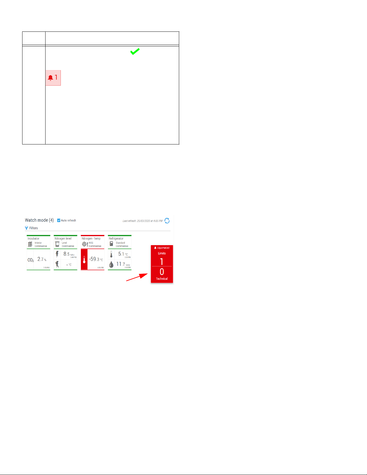
Table 4. (Cont.)Equipment Details
1
S.No Description
If there are no alarms, a green is displayed.
Otherwise, the number of alarms is shown in red
(low limit, high limit, technical alarm):
6
Click on the detailed equipment pane to close the equipment
window.
If the system detects an alarm while you are checking your
dashboard, an alarm panel appears on the right-hand side of
the screen (1), with counters to indicate the number of pieces
of equipment with alarms. This feature alerts if there are any
critical incidents. Click on the alarm panel to open the alarm
management window (see Acknowledging Alarms):
The number increments with the number of
detected alarms.
Click on the alarm counter to get more
information, acknowledge one or more alarms,
or generate an alarm report. This leads you
directly to the alarm management page (see
Alarms & Alerts).
Figure 23. Pop-up for alarm notification
14 | Home Screen Overview Smart-Vue Pro Monitoring Solution
Page 20

Users
Smart-Vue Pro includes a complete user management
interface. When you create your company account in SmartVue Pro (described in Creating your Smart-Vue Pro
Company Account), you also create the first user. The user
defined has the role of an “Application Manager” who can
create user profiles as well as manage all aspects of the
system.
Authentication Modes
Smart-Vue Pro supports several user authentication modes:
• Smart-Vue Pro’s own integrated user
authentication platform identifies users by their
user-name and password.
•An external authorization platform, namely
LDAP (Lightweight Directory Access Protocol)
identifies users by their corporate, network or system
login name and password. Generally used by large
organizations, this option provides consistent and
non-redundant user management while offering a
broader range of user permissions and password
control within corporate IT tools.
Adding an External
Authentication Platform: LDAP
For your system to access an external LDAP authentication
platform, you must add a new authentication mode to SmartVue Pro and configure it as described:
1. In the main menu, click Configuration
Authentication modes:
Then click
2.
(Add mode)
, which opens this screen
:
Default User Authentication
with Integrated Platform
In a default system, only the Smart-Vue Pro internal
authentication platform is used. To see the authentication
mode(s) used by your system, click Configuration
Authentication modes:
Figure 24. Default Smart-Vue Pro authentication
platform
CAUTION: The internal authentication mode
may not be disabled or edited in any way.
Figure 25. Adding an external authentication
platform
Name: Assign a name for the authentication mode. This
name is used as a reference by Smart-Vue Pro only and must
be unique within your entire Smart-Vue Pro system. If the
name is already in use, you will receive an error message.
Description: Enter optional information in this field.
URL: Enter the exact URL for connecting to your platform’s
LDAP authentication agent.
3. Click Connect. If the URL is correct and connection to
the LDAP authentication agent was established,
additional information is displayed:
Figure 26. Automatic options with LDAP
Smart-Vue Pro Monitoring Solution Users | 15
Page 21

In this example, the authentication agent was identified as
1
LDAP, which has the following two options:
Auto-create users: When users who do not exist in the
system try to login for the first time, the system creates them
automatically. They can login to Smart-Vue Pro and continue
with their regular credentials. Their user profile then shows
which authentication mode is being used (i.e. the name
assigned above in step (2)).
Auto-update users: With this option, information from user
profiles is automatically updated based on information in the
external directory.
If you change the URL to the authentication agent, the system
checks to make sure that the new URL corresponds to the
same agent as before. If not, an error occurs and you cannot
save changes.
Options for External
Authentication Platforms
Several options are available when you have configured one
or more external authentication platforms.
CAUTION: The user’s e-mail address must be:
1. Entered into the LDAP directory, otherwise
the user will not be imported.
2. Unique in the system (the same address
cannot be used more than once)
Editing an External
Authentication Platform: LDAP
You may edit an authentication mode that you have added to
the system (but not Smart-Vue Pro’s native authentication):
1. Click on Configuration
modes.
2. To change information, click on the Edit button () on
the line containing the authentication mode you want to
edit.
Authentication
CAUTION: You cannot edit or delete the
system’s internal authentication mechanism.
To access options for external authentication platforms
(LDAP):
1. Click on Configuration
modes.
Authentication
Figure 28. Editing an external authentication
platform
2. Click on the vertical dots ( ) (1) to access options:
Synchronize: This option connects to your LDAP agent and
fetches all the users configured as Users or Application
Managers for Smart-Vue Pro and creates them automatically.
This allows you to include users in alert rule definitions even if
they have not yet connected to Smart-Vue Pro (which would
create those users upon their first login if you enable the Autocreate option described previously). A message is displayed
to confirm the operation, informs you if any required
information is missing from any LDAP profile, or if the
connection could not be established.
Figure 27. Editing an external authentication
platform
16 | Users Smart-Vue Pro Monitoring Solution
Figure 29. Synchronize
Page 22
Note: If, Auto-create user and Auto-update users are not
selected (see Figure 26), the synchronize button only
updates the status of already-existing users (Enabled,
Disabled, Expired).
Disable: Prevents associated users from connecting to the
system.
Delete: You may only delete an existing authentication mode
if there are no associated users.
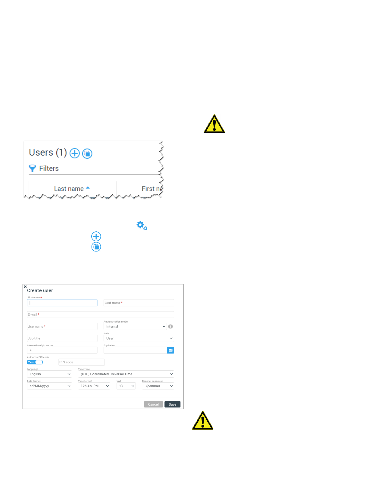
Adding a New User
Login to Smart-Vue Pro as an Application Manager and follow
the steps to add a new user:
Figure 30. Add new user
1. In the main menu, click on
You may either: Click on (Add user) or click on a username in the list and then (Create from selected) to use an
existing user as a template for creating a new one.
2. The new user identification window opens on the right
side of the screen, with fields either empty or with
information:
Configuration
Users
.
3. Enter the required information in the fields marked with a
red asterisk (*):
First name / Last name: Enter the first and last names.
E-mail: Enter the e-mail address to receive e-mail alerts
and confirmations sent by the system. Email id must be
unique as per 21CFR.
User-name: If you are using Smart-Vue Pro’s integrated
authentication, the user-name can either be the same as
the e-mail address or it may be a name that you enter
here.
CAUTION: When logging in, you must use
the information in the User-name field.
If you are using an LDAP authentication agent, the
user-name is your regular corporate system user-name (in
the format: authentication_mode /username).
Authentication mode: This field enables you to choose
whether to use Smart-Vue Pro’s internal authentication
(based on user-name and a password) or an external
LDAP platform using the regular corporate system credentials. The option specified when creating the company
account is displayed here by default.
When you select LDAP, a confirmation button is displayed
to test access directly from this screen.
Job title: Enter the role within the company.
International phone: Enter the telephone number in
international format, with the prefix “+[country code]”,
such as: +14153817894. Do not include any extra digits
or leading zeros.
Expiration date: When using Smart-Vue Pro’s native
authentication mode, you may set a date at which this
user account will expire. For external authentication platforms, you may not change the expiration date here.
Role: Assign the overall role within the Smart-Vue Pro
solution by choosing one of the following options:
• Application manager: Controls all aspects of the
entire system, from managing licenses to adapting
the individual profiles of other users.
• User: This type of user starts with view only access.
Additional Rights such as acknowledging alarms and
managing data logging are then added by an
Application Manager at an organizational level (See
Organization with Sites and Departments),
offering flexibility.
CAUTION: When using external authentication
Figure 31. User details
Smart-Vue Pro Monitoring Solution Users | 17
platforms, you may not change the role directly
via Smart-Vue Pro.
Page 23

Authorize PIN code: This option allows you to deter-
1
mine whether the user is allowed to perform actions that
require a PIN code:
• Acknowledging alarms via the Smart-Vue Pro data
logger screen.
• Acknowledging telephone alerts.
• Accessing advanced settings menus on the SmartVue Pro data logger screen.
Indicates that you can have a PIN code.
Indicates that you will not have a PIN code.
PIN code: If you are authorized to have a PIN code, enter
4 digits into this field. For additional security, the system
will complete the PIN code with 2 additional random digits.
CAUTION: To see the full 6-digit code, open
your profile and select PIN code
other system users, including Application
Managers, can see another user’s full PIN code.
Show. No
3. The user identification window is displayed:
Figure 32. Details for selected user
4. The account status is indicated next to the
name (1): indicates green if the status is OK; red if the
account is expired or blocked; or grey if the account is
deactivated.
Language: You may change the application language at
any time. Select your default language from the Lan-
guage pull-down menu.
Time zone: Select the time zone based on the geo-
graphical area when first logged in.
Date format: Choose the date format to be displayed in
the application.
Time format: Choose the time format to be displayed in
the application. Readings can be displayed in 12-hour
(AM/PM) or 24-hour format.
Unit: Choose the unit of temperature to be displayed in
degrees Celsius (°C) or Fahrenheit (°F).
Decimal separator: Select the character (period or
comma) to use as a decimal separator in numerical values in the Smart-Vue Pro display.
4. Click Save to create the user profile or Cancel to return
to the previous screen.
Editing a User
To edit any information in your Smart-Vue Pro system:
5. To edit any information, click on the button in the top
right-hand corner of the window and edit the fields as
needed.
6. Click Save to save your changes or Cancel to exit this
screen without saving changes.
CAUTION: Changes made to an existing user:
1. The user's e-mail address cannot be
changed, as it serves as a unique identifier
for this user in the system.
2. If an external authentic mode (LDAP) is being
used by the system, and the option “Autoupdate users” is activated, then some user
information presented here may not be
modified. If you change the Authentication
mode, test the user’s account validity by
clicking on the test button: .
3. For traceability reasons, it is not possible to
delete a user profile from the database. A
profile can only be disabled.
4. Any changes will take effect the next time the
user logs in to the system.
1. Click Configuration
2. Click on a line in the table to view or edit the profile.
18 | Users Smart-Vue Pro Monitoring Solution
Users.
Page 24

Updating Contact Details
CAUTION: If you want the user to receive alert
notifications by e-mail and/or SMS, you must first
assign the user to a Call Group as described in
Alert Rules with Users.
To edit contact details for a user associated with an alert rule:
1. Click Configuration
2. Click on a line in the table to edit that user’s profile.
3. The user details appear at the right of the screen.
4. Click Options at the top right of the user profile and
then click Edit contact information.
Users.
With Smart-Vue Pro, you may customize alert rules to meet
your needs (such as daytime hours, night calls, shift work,
etc.) and each alert rule can contact multiple users. Once you
add a user to an alert rule, you may modify that user’s contact
information accordingly, such as to have different phone
numbers or e-mail addresses at different times.
For the various alert types, you may add up to 2 phone
numbers and 3 email addresses by clicking on Add ().
CAUTION: Smart-Vue Pro Alert notification via
voice messaging works with all types of phones
in many regions. SMS/text messages are
supported on most mobile phones.
Remember to enter the “+” sign and country
code prefix for both your mobile and land-line
phone numbers.
You cannot disable a user account if that user is
associated with an alert rule.
Changing a User Password on
a System with Integrated
Figure 33. Accessing contact information
Enter the telephone numbers and/or e-mail addresses for the
different types of alerts you have configured, as described in
Configuring Alert Rules.
Authentication
CAUTION: This section does not apply to users
in systems using external authentication (LDAP).
The audit trail is updated to reflect a password
change, unless the new password and existing
password are identical.
Who can change a password? Users can change their own
passwords. Users with Application Manager rights can initiate
a password reset for other people but cannot actually set the
password for someone else. In all cases, users must set up
their own passwords.
To change your own password:
1. Click on your user profile in the upper right-hand corner
of the screen then click on Profile.
2. Your profile window opens directly.
3. Click Options ( ) in the top right-hand corner of the
window and select Change password.
4. Enter the new password and re-type it in the second field
to confirm.
5. Click OK to save your changes or Cancel to return to the
previous screen.
Figure 34. Editing contact information
CAUTION: Passwords should be at least 8
CAUTION: These fields are independent from
any external authentication (LDAP) platform
information.
Smart-Vue Pro Monitoring Solution Users | 19
characters long and contain a combination of
upper-case and lower-case letters with at least
one number and one special character.
Page 25

Resetting a User Password
An application manager may launch the password
reinitialization process for another user. That user will be
forced to change their password upon the next login:
1. Click Configuration ( )
2. Click on the user profile for which you want to reset the
password. The user details appear at the right of the
screen.
3. Click Options ( ) at the top right of the form and select
Reset password.
4. In the password reset window, click Yes to proceed with
the change or No to return to the previous screen:
Users.
Note: If the user’s account is not locked or expired, it is still
possible to connect even if the password has not been
reinitialized.
Adding an Account Profile
Picture
Smart-Vue Pro can personalize your display with a profile
picture when you are logged in to the system. The picture is
shown in the upper right-hand corner of the screen.
Picture recommendations:
• Maximum size: < 1 MB
• JPG or PNG format
To add a profile picture:
1. Click on your user profile image () in the upper righthand corner of the screen, then click Profile to open
your profile directly (or click Users in the
left-hand menu and select your name in the user list).
Figure 35. Password reset confirmation
5. The password recovery email is sent to the user with
instructions to reset the user password as shown below:
Figure 36. Resetting a user's password
2. Click Options () in the top right-hand corner of the
window and select Edit photo.
3. Click Choose file:
Figure 37. Selecting a profile picture
4. Browse your computer to locate the image you want to
use and then click Open.
6. The change is taken into account when the user clicks
OK.
7. The regular login screen is displayed the next time the
user logs in and user is prompted to enter the new
password. The user cannot login without changing the
password.
20 | Users Smart-Vue Pro Monitoring Solution
Page 26

5. The image is uploaded and displayed in Smart-Vue Pro.
Figure 38. Deleting a profile picture
6. Click Send to save your changes and update your
profile.
7. To delete the picture linked to the user profile, click
() in the screen shown above.
Account Profile Overview
To view/edit your general profile information:
1. Click on your user profile image in the upper
right-hand corner of the screen, then click Profile. The
screen contains two main sections:
Information: This section indicates the status of your
profile (Active / Inactive), its creation date and expiry date
(if entered), your user level, the language selected and the
PIN code to be typed on a Smart-Vue Pro data logger
screen to acknowledge alarms. You may edit this information by clicking on the Edit icon ().
Localization settings: Display format for time zone,
time format, date format, measurement unit, and decimal
separator. You may edit this information by clicking
Options ()
2. Click Save to record your changes, or Cancel to return
to the previous screen without saving changes.
Edit localization settings.
Smart-Vue Pro Monitoring Solution Users | 21
Page 27

User Access Profiles
The concept of profiles described in this section is closely tied
to that of your “organization”.
(Roles)
Initially created with a “User” profile, Smart-Vue Pro users can
have a variety of different access rights to match tasks,
responsibilities and the organization to which they belong.
An Application Manager profile can manage all aspects of the
system, whereas a user has limited access to application
features and menus. User access is further refined by
assignment to the organizational as a whole or one or more
sites and departments.
CAUTION: Users with a user profile must be
given rights within the organization in order to
view and manage configured equipment or data
logging information.
Table 5. Access differences between Application Managers and Users
Main menu items Application
User profile
Manager profile
Access Visibility based on Organization-Site
Department
Home
(Dashboards)
Equipment All Limited Yes
Alarms All Limited Yes
All
Limited Yes
Reports All Yes Yes
Data loggers All No No
Sensors All Yes No
Infrastructure All No No
Company
Users
Profiles
Organizations
Configuration
Time slots
Days off
Alerts
Data logging templates
Plans
Authentication modes
Help Yes Yes No
Organizations Yes
22 | Users Smart-Vue Pro Monitoring Solution
Page 28

Adding a New Profile
Profiles are comprised of different access rights or roles. A
user may have different roles in different parts of an
organization. For example, an user could be limited to viewing
information in one department and only be allowed to
acknowledge alarms in another.
A profile is assigned to a user based on their roles and
responsibilities in your organization. Profiles enable you to set
specific permissions and authorizations for each type of user.
Smart-Vue Pro starts with three default profiles: Manager,
User and Acknowledger. Only Application managers can
add or customize user profiles.
To add a new user profile:
Fill in the fields as required:
Name: Enter a name for the new user profile.
Description: Enter a description for the user profile (optional).
Rights: The rights listed here define what a user is and is not
allowed to do with Smart-Vue Pro.
To grant permissions, check the right(s) you want to assign to
the profile:
Manage organization: The user can set up and configure
the system’s organizational structure and include other users
as allowed.
Manage data logging: The user can set up data logging for
equipment.
Acknowledge alarms: The user can acknowledge alarms.
1. In the main menu, click on Configuration
Profiles.
2. Then click on (Add profile):
Figure 39. Available user profiles
3. The Create profile window opens as shown here:
Manage metrology parameters: The user can update
calibration settings.
To assign all these permissions at once, click on the check
box above the rights list, which selects all check boxes.
Figure 40. Adding a new user profile
Smart-Vue Pro Monitoring Solution Users | 23
Page 29

Your Organization
Company Information
You may update all company information at any time, except
for the main contact e-mail address.
General Information
To update your company account:
1. Click Configuration
Company.
Language: Choose the desired default language for your
company. Users are free to choose their personal preference
at any time.
Time zone: Select the time zone based on the primary
geographical area for the company.
Date format: Select how dates are displayed in the
application.
Time format: Select how time is displayed in the application.
Readings can be displayed in the 12-hour (AM/PM) or
24-hour format.
Unit: Temperature can be displayed in degrees Celsius (°C)
or Fahrenheit (°F).
Decimal separator: Select the character to use as a decimal
separator in numerical values.
Logo: If you want to add a logo image for your company,
click on Choose file (JPG or PNG format, maximum size 1
MB). This image will be used in a future release to personalize
application features
3. Make the desired changes directly in the form and then
click on Save to save the information.
Figure 41. Company account information
2. Fill in the required fields (marked with *) as appropriate.
Company name: Enter the name of the company.
Platform: Unique company identifier, filled in automatically
based on the company name entered.
Company address: Enter City, Postal code, Country,
International phone number relevant to the company.
CAUTION: Make sure you enter the telephone
number in international format, with the prefix
“+[country code]”, such as: +14153817894.
Do not include any extra digits or leading zeros.
The following settings apply as a default for your system. They
can be overridden by each user’s individual settings for local
operation and display purposes, but this information is used
as a common reference for the company in case users have
conflicting profile settings for shared actions. For example, if
you have e-mail alerts sent to user in different regions, English
could be the default company language for a same alert
message.
Managing License Keys
Access to Smart-Vue Pro is based on one or more service
subscriptions linked with the number of sensors in your
system. The following services require a subscription:
• Smart-Vue Pro web application and all integrated
features (including 24/7 alerts by e-mail only) for a
specified number of measurement points.
• Smart-Vue Pro Alert notification system, an
additional service that provides 24/7 alert notification
by telephone voice call and/or SMS-text message (to
a cellular telephone).
CAUTION: Contact an authorized Thermo
Scientific representative for more information.
When you sign up for one (or both) of these subscriptions, you
will receive the associated voucher number(s) to enter in
Smart-Vue Pro.
24 | Your Organization Smart-Vue Pro Monitoring Solution
Page 30

To view information about your Smart-Vue Pro solution
or add a new license key:
License Expiration
1. Click Configuration ( )
This page shows information related to your licenses,
such as activation key codes and expiration dates. The
Thermo Scientific technical support team may ask you to
provide this information if you contact them for
assistance.
2. To enter a new voucher number, click ( ) (Add
license key).
Figure 42. Adding a new license key
3. Enter your new voucher number in the pop-up window:
License keys.
(90-day Reminder)
As the expiration date for any of your licenses draws closer, a
reminder is displayed in the Notifications menu ( ) as
shown here:
Figure 45. Reminder to renew license
This reminder is displayed starting 90 days before the license
expiration date and remains present until the issue is resolved.
Lines containing license keys that have reached their
expiration date are shown in Grey with italic text:
Figure 43. Entering the new license key number
4. Click Save to register your license or Cancel to discard
changes and return to the previous screen.
5. Once the license key is registered, the activation key
number is shown in the table along with the license type
and expiration date.
Figure 44. Monitoring system’s licenses
Figure 46. Expired licenses indicated in Grey
Renewing or Upgrading your
License
To renew the license within the expiration date or upgrade
your current license (such as to expand the number of
authorized measurement points), enter the new license
number as described earlier in Managing License Keys.
Organization with Sites and Departments
The Smart-Vue Pro monitoring system is comprised of one
Organization, which may be sub-divided into Sites and
Departments. This flexibility enables you to create a logical
hierarchy for managing your system based on geographical,
operational or any other criteria that may be useful to you.
Smart-Vue Pro Monitoring Solution Your Organization | 25
Page 31

For example, you could create a hierarchy as shown in the
1
following figure
Figure 47. Creating a hierarchy that is appropriate
for your organization
Users, equipment and infrastructure devices are assigned to
the various entities in the overall organization. Users may even
have different profiles in different parts of the organization
such as someone who is a manager in the Los Angeles
laboratory but has view-only rights for the facility in New
Jersey.
Figure 47c. Sample organizational structures with
users assigned at level 3
Assigning an User to a Department
When you first start, you have one organization with the
Application Manager – the user who created the
account – listed as Manager (profiles are discussed in the
previous chapter). Application managers are associated
automatically with all the nodes in the organizational structure.
Those users cannot be removed.
You must first create users (see Users) in order to add them
to your sites and departments.
To associate a user with a department:
CAUTION: Equipment and infrastructure devices
(such as receivers) can only be assigned to one
entity in the hierarchy.
An organization can have from one to three levels
(Organization, Site and Department). There is no requirement
to create sub-divisions with this feature, though it tends to
make management much more intuitive than a “flat” structure.
You may associate users at whichever level of the
organization works best for you. Here are three examples:
Figure 47a. Sample organizational structures with
users assigned at level 1
1. In the Configuration
Associate users () (1).
Organizations menu, click
Figure 48. Adding a user to a department
The Associate user window opens as shown here:
Figure 47b. Sample organizational structures with
Figure 49. Associate user window
users assigned at level 2
26 | Your Organization Smart-Vue Pro Monitoring Solution
2. Depending on the department to which the user is
assigned, select the profile you want to assign to them
Page 32

using the Profile drop-down list. A profile determines the
1
1
actions that the user can perform and the objects that
they can manage in Smart-Vue Pro.
There are three user profiles:
• Acknowledger: This user profile allows you to
acknowledge alarms issued by the system for the
sensors they are monitoring. You may also disable
those sensors, if necessary.
• Manager: A Manager can access all application
features and manage other users.
• User: User rights are limited to viewing only. These
users do not have access to management and
configuration windows.
3. Add users to your organization:
Available: Select a user from the list of Available users. Then
click to move the user to the list of Selected
users on the right-hand side.
To select multiple users at a time, press and hold
the Ctrl key and click on each of the users you
want to select. Click to add them to the list of
Selected users. To select all available users, click
.
3. Enter a name for the new site in the pop-up window and
click Save.
Figure 51. Entering the new site name
The new site appears in your organization’s tree structure.
You may click or the triangles ( ) in the tree to
expand and contract the view.
Adding a Department
1. Click Configuration ( ) Organizations.
2. In the organization’s tree structure, click on the site and
then on Add department (2):
Selected: To remove an user from your organization, click on
that user in the list of Selected users and then click
to move the user to the list of Available users on
the left-hand side.
To remove multiple users, press and hold the Ctrl
key and, while holding down the key, click on each
of the other users you want to remove. Click to
move them to the list of Available users on the left.
To remove all users, click .
4. Click Save to save your changes or Cancel to exit this
screen without saving changes.
Adding a Site
To add a new site:
1. Click Configuration ( )
2. Click on the name of your company account and then
click Add site (1).
Organizations.
Figure 52. Adding a new department
3. Enter a name in the pop-up window for the new
department and click Save:
Figure 53. Entering the new department name
Figure 50. Adding a new site
Smart-Vue Pro Monitoring Solution Your Organization | 27
Page 33

The new site is listed in your organization’s tree structure:
Figure 54. Organizational structure
The create plan window opens as shown here:
Figure 56. Adding a new floor plan
Editing / Deleting a Site or
Department
To manage different sites and departments, click on the
desired node in the organizational structure and use the
available options:
New To add a new site or department, click .
Delete To delete a site or department, click .
Edit To edit a site name, click . Modify or enter a new
name and click to confirm your changes.
Adding Plan Images
Smart-Vue Pro allows you to visually place your equipment on
floor plan representing the layout of your organization. Plans
are useful for identifying the locations of the sensors
associated with the equipment you are monitoring. You may
add as many plans as required.
To add a plan:
3. Enter a name for the floor plan in the Name field.
4. You may add a description in the Description field
(optional).
5. Click Choose file and select the desired image of your
premises (JPG, PNG or GIF format up to 1 MB maximum
size). A preview image is displayed after you load the floor
plan:
1. In the main menu, click Configuration
2. Click Add plan ( ) to import a plan image.
Figure 55. Managing plans
28 | Your Organization Smart-Vue Pro Monitoring Solution
Plans.
Figure 57. Adding a new floor plan
6. You may click on the thumbnail image to open the
enlarged floor plan.
Page 34

Placing Equipment on the Plan
1
Once you have loaded one or more floor plan images, place
the equipment on the image according to its physical location.
To place equipment on the plan:
1. In the main menu, click Equipment ().
2. Select the equipment you want to place on the plan. The
equipment details are shown on the right-hand side of
the screen.
3. Click Options () in the upper right-hand corner of the
equipment window and then click Edit location.
4. Select the desired floor plan using the Plan drop-down
list to display a larger image.
5. Place your equipment by clicking the desired location on
the image. The blue location pin () moves to show the
new position (1). The grey pin represents the previous
equipment position, which disappears after you save the
new equipment location.
Figure 58. Placing an equipment on the plan
If you want to remove the equipment from the image, you may
click on the Remove association button ().
6. Click Save to save the equipment location (or removal) or
click Cancel to return to the previous screen without
saving the changes.
Smart-Vue Pro Monitoring Solution Your Organization | 29
Page 35

Infrastructure Devices
This section allows you to add different infrastructure
components that comprise your monitoring system, such as a
LoRaWAN receiver, an alarm device, etc,.
Your LoRaWAN connection must be available to interact with
LoRaWAN enabled devices, that is, a Thermo Scientific
LoRaWAN-enabled receiver must be installed and configured
to communicate with your Smart-Vue Pro system.
Adding Infrastructure
Follow these steps to add a new component to the system
manually:
1. Click Infrastructure in the main menu and then
click :
Serial number/Node ID: Enter the serial number on the
back of your infrastructure element (device).
The system identifies the element based on its serial number.
If you enter an incorrect serial number, a red exclamation
mark is shown in front of the corresponding field. Check the
serial number and try again. If the problem persists, contact
technical support.
Typ e: For infrastructure elements, the Type is selected
manually. It is therefore essential to enter the correct identifier
(e.g. serial number, node ID). If the type does not correspond
to the entered identifier, the application cannot communicate
with the device.
Name: Enter a name for the infrastructure component. This
name is used as the reference in all lists.
Inventory code: (Optional) Enter the inventory code of the
infrastructure element for information purposes.
Organization: Use the drop-down list to select the
department to which the infrastructure element is associated.
It may be helpful to associate topology with an infrastructure
element to target precise alert management and alarm
acknowledgment rights.
Note: To add other departments, follow the procedure
described in Organization with Sites and Departments.
Figure 59. Click to add infrastructure
The Create infrastructure window opens as shown here:
Figure 60. Adding infrastructure details
2. Enter the details of the infrastructure element. Fields
marked with a red asterisk (
*) are required:
Description: (Optional) You may enter a description of the
component for information purposes.
Trigger alarm after: Check this option and enter the delay (in
minutes) after which the system will trigger an alarm if the
infrastructure component is not responding. This mechanism
ensures early notification in case of problems or a
communication error.
Repeat alarm every: Check this option to set the repeat
frequency for this alarm and specify the desired time interval
in the entry field.
3. Click Save to save your infrastructure component, or
Cancel to close this window without saving changes.
30 | Infrastructure Devices Smart-Vue Pro Monitoring Solution
Page 36

Editing Infrastructure
To manage existing infrastructure, use the following options:
5. Click Save to keep your changes or Cancel to return to
the previous screen without saving changes.
1. In the main menu, click Infrastructure.
2. Click on a line in the table to view or edit the desired
device.
Figure 61. Editing infrastructure details
3. Click Edit () on the right-hand side of the screen and
edit information directly as necessary.
4. Several other functions are available under Options ():
Options Category Description
Alarm
history
Click to disable the
siren’s functionality (in
the Infrastructure list, a
filter enables you to
display or hide disabled
infrastructure).
Adding a LoRaWAN Receiver as Infrastructure
LoRaWAN wireless technology is a key feature of the SmartVue Pro system.
In terms of configuration, the LoRaWAN receiver is entirely
configured on the receiver itself, as described in the SmartVue Pro LoRaWAN Receiver User Guide, which you may
access online via the Help menu of the Smart-Vue Pro web
application. That is, the receiver contains its own
configuration interface, which includes information on sending
data to your Smart-Vue Pro system.
You are not required to configure the receiver via the SmartVue Pro web application. However, if you do not add the
receiver to your Smart-Vue Pro infrastructure via the web
application, then you will not receive alerts in case a technical
problem arises.
CAUTION: Even if it is not technically required to
add your LoRaWAN receiver as infrastructure via
the Smart-Vue Pro web application, we
recommend that you include it along with your
other infrastructure devices in order to receive
technical alerts in case of any problems.
Options
()
Simulate
an alarm
Disable
Remove
() Refresh
You may use this
function to simulate an
alarm as described in
the previous section
Opens the Alarm list to
see any alarms involving
this device (a filter is
applied to show
“Infrastructure” with the
siren’s serial number)
Click to remove the
siren from your system.
The siren is marked as
“removed” in the
Infrastructure list. If you
wish to restore the same
siren, you must create it
again by entering the
serial number.
Refreshes the
infrastructure
information window.
Smart-Vue Pro Monitoring Solution Infrastructure Devices | 31
Page 37

Data Loggers
The features described in this section are reserved for
application managers.
Adding Data Loggers
Adding a Data Logger
Manually
Follow these steps to add a Smart-Vue Pro data logger to the
system manually:
1. In the main menu, click Data Loggers () and click
to enter all the details for a new data logger, or to use
the selected data logger as a template for the new one
(1):
2. As you type in the data logger serial number, additional
fields are displayed:
Figure 64. Adding a new data logger
Figure 62. Data logger management window
The Create data logger window opens as shown here:
Figure 63. Data logger management window
before entering the serial number
3. Fill the data logger details as required. Options are
displayed according to the type of data logger. The fields
marked with a red asterisk (
Serial number: Enter the serial number from the from
top of data logger / from the information screen of data
logger. If you enter an incorrect serial number, a red exclamation mark is shown in front of the corresponding field.
Check the serial number and try again. Contact technical
support if the problem persists.
Typ e: This information is assigned automatically by the
system based on the serial number you enter.
Name: Enter a name for the data logger. This name is
used as the reference in all lists.
Inventory code: (Optional) You may enter an inventory
code for the data logger for information purposes.
Description: (Optional) You may enter a description of
the data logger for information purposes.
CAUTION: Alarms are always sent in real-time,
without waiting for the programmed transfer
interval.
*) are required.
32 | Data Loggers Smart-Vue Pro Monitoring Solution
Page 38

CAUTION: It is a general practice to allow 3
1
communication failures before triggering an
alarm.
Adding a Data Logger with the
Same Settings as an
4. Click Save to save the data logger in the database.
At first, the data logger is shown as follows:
Figure 65. Freshly added data logger
5. On your Smart-Vue Pro data logger: Tap the screen to
open the menu and click Sensors
to detect physically connected sensors and ensure that
the data logger is up-to-date internally before continuing.
6. In the Smart-Vue Pro web application: Click Refresh
Refresh sensors
Existing One
If you are setting up a data logger with settings that are
already configured, you can save time by clicking the icon
to use the selected device as a template for the new one.
Importing a Batch of Data
Logger
If you would like to set up several data loggers at once, you
may import a TXT or .CSV text file with values separated by a
semi-colon character (;). You must include at least the device
serial number and name, as shown in the following figure:
sensors on device icon (1) (above) to communicate
with the data logger and update the screen with the latest
information.
Figure 66. Example of data logger information
after refresh
Figure 67. Sample .CSV import file with data logger
serial numbers and names
You may also include the inventory code and data logger
description as shown here:
Figure 68. Sample .CSV file with additional
information
1. Click to import a batch file.
2. Browse to locate the.TXT or .CSV file on your computer.
3. Click Open to import the list.
Smart-Vue Pro Monitoring Solution Data Loggers | 33
Page 39

Viewing the Data Logger
1
1
4
5
7
3
6
2
8
Viewing Data Logger
List
All the data loggers you add to the system are shown in the
Data loggers screen:
Figure 69. List of data loggers stored in Smart-Vue
Pro
This screen displays all data loggers in the system, with
columns containing the information below. The data logger’s
status is indicated by red-green color coding on left-hand
edge of the table (1) (this does not indicate alarms related to
readings, just the data logger itself). You may click on the up/
down arrows () in the column headers to change the list for
ascending/descending order.
Details
Regardless of your Smart-Vue Pro user level, you may always
check the data for the data loggers you are authorized to
view.
To view the graph for a given data logger:
1. Click Data loggers in the main menu.
2. Select a data logger.
The data logger details are shown on the right-hand side of
the screen, with several sections:
Typ e: Type of data logger
Designation: A name you assign to the data logger. You
may click on the graph icon () to see a data graph and
other sensor information.
Serial number: Data logger serial number.
Version: Version of Firmware running on data logger.
Sensors: Number of sensors connected to the data logger.
Last activity: Date and time of last communication with the
data logger.
Power status: Plugged into AC adapter ( ) or battery level
().
CAUTION: The number of sensors that you may
use in your system is determined by your license.
You can only use the allowed number of sensors
simultaneously.
Figure 70. Data logger details
34 | Data Loggers Smart-Vue Pro Monitoring Solution
Page 40

Table 6. Data Logger Details
1
SNo. Description
1
The serial number, name and inventory code (if
present) of the data logger
Alarm counter indicating data logger status
(sensor related alarm and unexpected stop
indication are not shown in data logger alarm
status). In case of alarm, the icon changes color
and shows the number of alarms, for example:
Data Logger Actions
You may use the options available in the data logger details
screen to manage your data loggers.
1. Click Data loggers () in the main menu and select a
data logger in the list.
2. Click Options () (1) in the upper right-hand corner to
access available options:
2
Figure 71. Alarm counter in data logger
details
Hover over the alarm counter with your mouse to
view alarm details. If there are no alarms, the
indicator is shown.
Click on the alarm counter to get more
information, acknowledge one or more alarms,
or generate an alarm report. You will be directed
to the alarm management screen (see Alarms &
Alerts).
3
4
5
6
Indicator showing the power source being used
and estimated remaining battery level.
The Transfer interval indicates the frequency
with which data is transmitted by the data logger
to the Smart-Vue Pro system.
Alarm triggering and repeat rules, as defined
when adding the data logger. Hover over the
alarm counter with your mouse to view alarm
details.
Number of sensors associated with the data
logger. The active icon ( ) indicates sensors
with data logging in progress.
Sensors not yet programmed are greyed out, as
indicated by the inactive icon ( ).
Figure 72. Data logger options menu
Alarm history: Opens the alarm page for the selected data
logger (see Viewing Alarm Details).
Simulate an alarm: Allows you to simulate the occurrence of
an alarm on this data logger for testing purposes. The
simulation generates a Technical alarm (Communication lost,
Device mismatch, Lost power supply, Low Battery) that is
listed in the Audit Trail as an “Alarm simulation”.
Communication settings: This menu provides technical
information regarding data logger communications. Reserved
for qualified technicians. Incorrect use of data logger settings
could cause your system to malfunction. Contact Thermo
Scientific technical support for more information.
Disable: Enables you to effectively turn this device off and
stop data logging.
Remove: Enables you to completely remove this data logger
from your system and stops data logging. You may need to
do this in the event of a data logger swap or hardware
problem. If you choose this option, you must enter your
password to confirm the operation.
Click on the graph icon to view readings of
7
8 Sensor operating range.
Smart-Vue Pro Monitoring Solution Data Loggers | 35
sensor over time (measurements and associated
events.) or download the report in PDF, Excel or
Word format (see Viewing Sensor Data).
Page 41

Editing Data Logger Details
Follow these steps if you need to modify the information or
default values for your data logger:
1. Click Data loggers ( ) in the main menu and select a
data logger in the list.
2. Click Edit ( ) icon. This opens a window identical to
that described in Adding Data Loggers.
Note: You may not edit the serial number or data logger type
fields.
3. There following information is non-editable:
• Firmware version: the data logger’s firmware version
number.
• Last activity: the last time the data logger
communicated with the server.
4. Click Save to keep your changes or, Cancel to return to
the previous screen without saving changes.
36 | Data Loggers Smart-Vue Pro Monitoring Solution
Page 42

Sensors
2
8
3
5
6
7
4
1
Sensors that are connected physically or wirelessly to your
Smart-Vue Pro data loggers are added to the Smart-Vue Pro
web application automatically.
For Smart-Vue Pro to recognize the sensor(s) that are
physically connected to a Smart-Vue Pro data logger, click
Refresh Sensor and Synchronize in the data logger’s
Sensors menu. Once detected, these sensors are shown in
the sensor management window. From the sensor
management window, you may:
• Access detailed information about the sensor.
• Display readings in a graph, along with various other
information about the selected sensor.
• Manage calibration parameters.
Viewing the Sensor List
Sensors connected to the Smart-Vue Pro data loggers are
listed in the Sensors screen ():
Calibration: Hover your mouse over the field to see
calibration parameters or click to open the calibration
management window.
Latest value: Date and value of the most recently recorded
reading.
Viewing Sensor Details
Regardless of your user level in Smart-Vue Pro, you may
always check the data for sensors you are authorized to view.
To view detailed information about a sensor:
1. In the main menu, click Sensors.
2. Select the desired sensor.
3. The sensor details are shown on the right-hand side of
the screen, with several sections:
Figure 73. Sensor list in Smart-Vue Pro
This screen displays all sensors with the following information:
Typ e: Visual indication of sensor type.
Description: Sensor serial number, sensor type and
associated data logger.
Data logging: Data logging status: running () or idle
(). Move your mouse over the icon to see data logging
settings.
Equipment: The equipment associated with the sensor.
Smart-Vue Pro Monitoring Solution Sensors | 37
Figure 74. Sensor details
Page 43

Table 7. Sensor Detail Parts
SNo. Description
1 Sensor serial number and type.
2
3
Name of the equipment with which the sensor is
associated.
Name of the data logger on which the sensor is
attached.
from the information provided by sensor calibration
certificates.
CAUTION: Calibration parameters may be
corrected for your sensor(s) only when data
logging is disabled. If data logging is currently
running on a data logger, you must first stop data
logging before you can change calibration
parameters.
Limit alarm indicator (excursions with respect to
4
5
6
7 Last recorded reading.
8 Data logging configuration parameters.
programmed limits). Click on this indicator for
detailed information or to acknowledge an alarm.
Technical alarm indicator for the sensor. Click on
the indicator for detailed information or to
acknowledge an alarm.
Data logging status for this sensor: Running or
Idle
Calibration Parameters
It is important to calibrate the sensors on your Smart-Vue Pro
data loggers to fine-tune the accuracy of readings. The
calibration procedure is typically handled by Thermo
Scientific’s in-house metrology laboratory, which determines
precise correction coefficients.
CAUTION: Calibration parameters are stored
directly in smart-sensors. This means that all
sensor readings are adjusted for maximum
accuracy, though you may edit calibration
parameters if necessary. However, you may not
use Smart-Vue Pro to change calibration
parameters on remote (Bluetooth wireless)
sensors.
To update calibration information:
1. Login to Smart-Vue Pro as an Application manager.
2. In the main menu, click Sensors and click on the sensor
you want to update.
3. If calibration information has already been provided, you
may click Calibration ()
Otherwise, click Add () to enter and save new
information.
Edit ().
Figure 75. Creating or adding data logger
calibration parameters
Updating Parameters for
Calibrated Sensors
Smart-Vue Pro allows you to correct the parameters and
calibration information of your Smart-Vue Pro data loggers
38 | Sensors Smart-Vue Pro Monitoring Solution
4. Here, you may enter the information provided on the
sensor calibration certificate:
Coefficient A, B, C: Enter the correction coefficients in the
A, B and C fields. To ensure the accuracy of readings, enter
only valid parameters in these fields.
Drift: This value represents the loss of reading accuracy over
time. Values may drift lower by a few hundredths per year,
which can impact programmed data logging limits. Enter the
Drift value provided on calibration certificate.
Uncertainty: Uncertainty is the loss of calibration accuracy
with respect to the reference sensor (which has an impact on
alarm emission). Enter the value provided on calibration
certificate.
Page 44

Laboratory: Using the drop-down list, select the calibration
laboratory that issued the calibration certificate.
4-20 mA, 0-5 V, 0-10 V
Identifier: Enter the certificate reference number.
Date: Click in the Date entry field and choose the date on
which the sensor was calibrated from the calendar. The
current date is displayed by default.
Note: If calibration certificate information had been entered
previously for this sensor, the date you enter here must not be
earlier than that of the previous certificate.
Calibration and Reminder
Frequency
Once you have added calibration information, you may
choose to receive notification as a reminder to recalibrate the
sensor by a given date.
In the calibration screen, click Edit () and enter the
number of months after the certificate date at which the
system will remind you to recalibrate the sensor:
Loop Sensors
Description
4-20 mA current and 0-10 V voltage Smart-Sensors can be
connected to industry-standard devices that generate
appropriate output signal. The signal can be measured to
provide status information for a variety of applications,
including wind monitors, particle counters, ultra-lowtemperature (ULT) freezers and temperature, gas, VOC, and
relative humidity devices, and more. Read values are
converted into useful information by the Smart-Vue Pro web
application, then displayed both in the web application and on
the Smart-Vue Pro data logger display.
Figure 76. Sensor calibration parameters
Click Save () to update sensor information, Cancel ( )
to undo any changes you may have made, or Delete () to
remove notification.
Figure 77. 4-20 mA / 0-10 V Smart-Sensor
Table 8. Sensor wiring
Black Common ground
Red 0-10 V input
White 4-20 mA input
Connect the wires according the type of device you want to
monitor.
CAUTION: Do not connect all three wires
A sensor may only monitor one of the two input
parameters (red or white wire, but not both).
The maximum voltage on the 4-20 mA input wire
is 2 V. Exceeding this value will damage your
sensor.
Smart-Vue Pro Monitoring Solution Sensors | 39
Page 45

Mapping Values for Meaningful
1
Readings
For sensor readings to be relevant in your context, you must
map the low values (0 V or 4 mA) and high values
(10 V or 20 mA) to match the limit values produced by your
connected device. For example, on a 4-20 mA device, the
low 4 value could correspond to a CO
high 20 mA value could correspond to 10% CO
you would map 4 to 0 and 20 to 10 in Smart-Vue Pro. You
may use other units to meet your needs.
To do this:
1. Click Sensors in the left-hand menu.
level of 0% and the
2
. In that case,
2
The unit you specify here is shown in the Smart-Vue Pro web
application as well as on the data logger.
CAUTION: The mapping from 4 to 20 mA or 0 to
10 V is strictly linear.
The 0-10 V sensor is also used for 0-5 V output
devices. Simply adjust your Low and High values
accordingly.
Simulating a Sensor Alarm for Testing
2. Select the sensor you wish to modify from the sensor list.
3. Click Calibration ( ).
4. Edit the values in the Range zone (1) (below) to meet
your needs.
Low: The lower value output by your device.
High: The higher value output by your device.
Unit: The measurement unit you would like to display in
Smart-Vue Pro.
5. Click Save to save your changes or Cancel to close this
window without saving changes.
You may trigger a limit alarm on a sensor for testing purposes
to ensure that related alert rules and user contact work
properly. To test a sensor alarm:
1. Login to Smart-Vue Pro as an Application manager.
2. In the main menu, click Sensors for a list of the sensors
in your system.
3. Click on the sensor you want to test.
4. Click Options () and select Simulate an alarm from
the drop-down menu. You will then be able to see the
alarm in the Alarm list and Audit trail (indicated as
“Simulation” in both places). Any related alert rules for the
sensor are triggered, such as, e-mail or telephone alerts.
Removing a Sensor
You may remove sensors from the system, for example if they
are no longer used or if they have been replaced on the
Smart-Vue Pro data logger. To remove a sensor:
1. Login to Smart-Vue Pro as an Application manager.
2. In the main menu, click Sensors for a list of the sensors
in your system.
3. Click on the sensor you want to remove.
4. Click Options () and select Remove from the drop-
down menu. To remove a sensor, data logging must not
Figure 78. Mapping 4-20 mA / 0-10 V values
40 | Sensors Smart-Vue Pro Monitoring Solution
be running.
CAUTION: Smart-Vue Pro data loggers update
sensor information in Smart-Vue Pro
automatically based on the physically connected
sensor(s). When you plug in a new sensor (or
even plug the same one back in if it had been
removed accidentally), the sensor(s) will appear
again in the Smart-Vue Pro web application.
Page 46

Disabling / Enabling a Sensor
You may disable a sensor so that it cannot be used for data
logging or you can enable a sensor that has been disabled.
To do this:
1. Login to Smart-Vue Pro as an Application manager.
2. In the main menu, click Sensors from a list of the
sensors in your system.
3. Click on the sensor you want to disable or enable.
4. Click Options ( ) and select Disable (or Enable) from
the drop-down menu. To disable a sensor, data logging
must not be running.
CAUTION: Disabled sensors are no longer
shown in the sensor list. To enable a disabled
sensor, use the Filter option in the sensor list and
select Display disabled sensors. You may then
choose to enable it as described above.
Smart-Vue Pro Monitoring Solution Sensors | 41
Page 47

Equipment
This chapter describes managing equipment in the SmartVue Pro system and assigning data loggers and sensors to
that equipment.
The “equipment” in Smart-Vue Pro refers to the temperaturecontrolled chambers, cabinets, refrigerators, tanks,
enclosures, and other spaces you may choose to monitor
with Smart-Vue Pro data loggers.
Adding Equipment
To add equipment:
1. Click Equipment () in the left-hand menu. There are
two options for creating new equipment:
• Click to enter details manually
Or
• Click to select an existing piece of equipment and
click to use that equipment as a template to
create new equipment:
The Create equipment window opens as shown here:
Figure 80. Adding new equipment
2. Fill the equipment details. The fields marked with a red
asterisk (
Name: Enter a name for your equipment. This name is
used in all lists.
*) are required:
Figure 79. Equipment management window
Inventory code: (Optional) You may enter an inventory
code for the equipment for information purposes.
Typ e: Enter a type of equipment in the field.
Icon: Click on the icon and select the most appropriate
symbol to visually represent the equipment.
Organization: Equipment is assigned to sites and
departments.
You must assign an organization to your equipment using
the pull-down menu. To add a department to this list,
click Configuration Organization and follow the
instructions provided earlier in Organization with Sites
and Departments.
Critical / Not critical: Determine the criticality level for
the equipment by clicking on the appropriate option.
This information is used to fine-tune the data logging
mode and alert rules based on equipment criticality.
Mobile / Static: Indicate whether the equipment is dedi-
cated to a static environment (refrigerators, freezers,
water-baths) or a mobile environment (coolers, packages).
3. Click Save to save the equipment or Cancel to close this
window without saving changes.
42 | Equipment Smart-Vue Pro Monitoring Solution
Page 48

The equipment is listed in the equipment management
1
screen:
Figure 81. Equipment list in Smart-Vue Pro
Associating Sensors with
Equipment
4. Tick one or more check boxes to select the
corresponding sensor(s):
This section describes assigning one or more sensors to
monitor equipment.
To associate a sensor with equipment:
1. Click Equipment () on the left-hand side of the menu
to see the list of equipments you are allowed to manage.
2. Click on the equipment to which you want to add a
sensor.
3. Click on Add () (1):
Figure 82. Equipment details
Figure 83. List of available sensors
5. Click Save to complete the association or Cancel to exit
this screen without saving changes.
Dissociating Sensors from
Equipment
CAUTION: You may only dissociate sensors
from equipment if they are not being used for
data logging. If the sensor is being used for data
logging, you must first stop data logging as
described in Stopping Data Logging, and then
dissociate the sensor from the equipment.
To dissociate a sensor from equipment:
1. Click Equipment () in the main menu to see the list of
equipment you are authorized to manage.
2. Click on the equipment from which you want to remove a
sensor.
Smart-Vue Pro Monitoring Solution Equipment | 43
Page 49

3. Click Remove association ( ) (1) next to the sensor
1
1
2
3
4
5
6
7
8
9
you want to remove:
3. The equipment details are displayed as shown below:
Figure 86. Equipment details
Figure 84. Dissociating a sensor from equipment
4. Click Yes and confirm the operation when prompted, or
click No to return to the previous screen:
Figure 85. Confirming sensor dissociation
Viewing Equipment Details
Regardless of your user level in Smart-Vue Pro, you may
always check the data for the equipment you are authorized
to view.
For a complete view of all equipment details, including sensor
readings:
1. Click Equipment () in the main menu.
2. Select the desired equipment.
Table 9. Equipment Details
SNo. Description
1 Equipment name and type.
2
3
4
5 Opens a graph with all sensor readings.
6
7
8
9
Organization and department (if configured) to
which the equipment is associated.
Current alarm indicator. An alarm is an “out-ofbounds” state or other error detected on a data
logger or sensor. Hover your mouse over the
indicator or click on it for details or to
acknowledge an alarm.
Mobility indicator (Mobile or Static) and
equipment status (Enabled or Disabled).
Programmed upper and/or lower limits for the
sensor and indication of data logging status.
If you have placed the equipment on a plan, click
Plan to view the exact location of the equipment
on the map.
Shows most recent values reading for this
sensor. A dash ( - ) is displayed if no readings are
available.
Click to associate other sensors with the
selected equipment.
Click to remove the sensor from its current
equipment.
Click to set sensor settings and start data
logging (password required).
Click to stop data logging (password
required).
44 | Equipment Smart-Vue Pro Monitoring Solution
Page 50

Modifying / Managing
1
Deleting Equipment
Equipment
You may use the options available in the equipment details
screen to manage the equipment in your Smart-Vue Pro
system.
1. Click on Equipment ( ) in the main menu.
2. Select the desired equipment.
3. Click on Options () in the upper right-hand corner of
the screen and then click on one of the available options:
Figure 87. Equipment details
Alarm history: Opens the alarm page for the selected
equipment (described in Viewing Alarm Details).
Edit location: This option is only available for "Static"
equipment, allowing you to locate the equipment on a
floor plan or change its position on the plan (see Placing
Equipment on the Plan).
You may delete equipment only if the following conditions are
met:
• The equipment must not be associated with a sensor.
• If one or more sensors are associated with the
equipment, you must first unpair the sensor(s) before
deleting the equipment. See Dissociating Sensors
from Equipment for more details on this feature.
To remove equipment:
1. Click Equipment () in the main menu.
2. Select the desired equipment.
3. Click Delete ( ) (1) to remove the selected equipment:
Figure 88. Equipment management window
4. Click Yes to confirm the operation when prompted, or
click No to return to the previous screen:
Note: Disable / Enable: Select this option to disable
equipment or enable equipment that has been disabled.
Disabled equipment is no longer shown in the equipment
list or as a tile in the Watch Mode display.
Note: Equipment cannot be disabled if data logging is
currently running on one of its sensors. To enable
disabled equipment, use the Filter option in the
equipment list and select Display disabled equipment
to enable it.
Delete: Removes the selected equipment from the system.
Edit: To modify the information for existing equipment,
click on Edit (). Click Save to keep your changes, or
Cancel to return to the previous screen without saving
changes.
Refresh: Click Refresh () to update the information
in this window.
Figure 89. Confirming equipment removal
Smart-Vue Pro Monitoring Solution Equipment | 45
Page 51

Data Logging
1
2
To use your Smart-Vue Pro data logger, you must first
program data logging.
CAUTION: Data logging is configured at the
equipment level. Once you have assigned a
sensor to equipment (described in Associating
Sensors with Equipment), you may set up data
logging.
Data logging consists of recording physical parameters (such
as temperature and humidity) over time. Sensor readings are
recorded based on a set of configuration options that are
used to manage your data logger while data logging.
Data logging parameters include:
• The sensor reading frequency.
• High and low alarm limits.
How does it work?
Here is a quick overview of the data logging flow with
Smart-Vue Pro:
Starting Data Logging
CAUTION: A sensor must be associated with
equipment in order to start data logging.
To configure data logging:
1. You can start data logging either via Equipment () or
Data Loggers ( ) in the left-hand menu as long as the
sensor is associated with equipment. The instructions
below are identical for both cases.
2. Click on the name of the equipment (1) (or data logger)
for which you want to start data logging:
1. The Smart-Vue Pro data logger equipped with sensors is
installed on the equipment to be monitored.
2. Sensor readings are collected by the Smart-Vue Pro data
logger, which then sends the data to the Cloud or your
server via LoRaWAN
3. Smart-Vue Pro enables you to manage every aspect of
your system, equipment, users, and data. When limits are
exceeded or other anomalies are detected, an alert is
displayed on the Smart-Vue Pro data logger. You can
receive alerts 24/7 from the Smart-Vue Pro system.
wireless connectivity.
Figure 90. The Smart-Vue Pro data logger
communicates with Smart-Vue Pro via an onpremises LoRaWAN
receiver
Figure 91. Click on a piece of equipment to set up
data logging
3. Details and available sensors are shown on the righthand side of the screen. Click Start data logging button
() (2) to access sensor settings:
Figure 92. Choosing a sensor for data logging
46 | Data Logging Smart-Vue Pro Monitoring Solution
Page 52

4. Enter your system password and click Send to continue.
3
2
1
Figure 93. Entering password to enter data logging
settings screen
The Start data logging window opens, with several zones (in
the image below):
• General sensor properties (1).
• Choosing to create a new data logging configuration or
selecting an existing configuration (2).
Reading interval: The frequency with which the sensor
records a reading. Use the drop-down list to select the
value that meets needs.
Use drift/uncertainty: Select this check box if you want
to take into account the deviation and uncertainty values
provided for the sensor (see Updating Parameters for
Calibrated Sensors).
2. You may set low and high limits to ensure that the
physical parameter(s) in the monitored environment
remain(s) within a specific range of values.
CAUTION: You may enter up to three high
limits and three low limits to benefit from
multiple warnings if limit excursions persist.
You may enter the limits in any order that you
choose. The first one you enter is displayed
on the Smart-Vue Pro data logger display.
• Entering specific parameters (3).
Figure 94. Defining data logging parameters
5. Define the settings for a new data logging session as
described in the next section or select an existing
configuration.
Data Logging Details
Low limits: The lowest acceptable sensor reading (lowest
temperature, lowest humidity level, etc). Any readings below
the limit(s) will trigger an alarm. Click to set up additional
limits or to remove limits you may have added.
Low delay: The duration of the reading that can remain lower
than the low limit before an alarm is triggered (must be a
multiple of the reading interval, in minutes).
High limits: The highest acceptable sensor reading. Any
readings above the limit(s) will trigger an alarm. Click to set
up additional limits or to remove limits you may have
added.
High delay: The duration of the reading can remain higher
than the high limit before an alarm is triggered (must be a
multiple of the reading interval, in minutes).
If a reading exceeds these limits when data logging is running
(and the delay is reached, if configured), you will be notified of
the alarm by a color change on the data logger screen and
outer ring, and via the system’s alert mechanism.
While the data logger is in an alarm state, the Smart-Vue Pro
data logger buzzer will also emit an audio alarm when
plugged into AC power.
If you are an Application Manager or have manager rights in
your branch of the organization, you may create configuration
templates with data logging settings that you can use later
when programming similar sensors.
If there are no templates, the New data logging
configuration field is selected by default. Previous settings
are displayed if the sensor has already been used.
1. Set the following information:
New configuration: This option is selected by default
(configuration template feature not yet implemented).
Smart-Vue Pro Monitoring Solution Data Logging | 47
Page 53

3. Click Start to begin recording sensor readings.
1
1
4. Confirm your action by entering your password in the
pop-up window:
Figure 97. Entering your password to stop data
logging
Figure 95. Equipment details with data logging in
the process of starting
Data logging in the process of being started is indicated by a
timer icon () in equipment details screen (1). The timer
changes to ( ) when data logging is running.
Stopping Data Logging
You may stop data logging that is currently running:
1. In the main menu, click Equipment ().
2. Click on the name of the equipment for which you want
to stop data logging
3. Sensors for which data logging is in progress have a
Stop data logging button (). Click on the button (2)
to stop data logging:
If you select Force stop, data logging is stopped at the next
programmed transfer interval without retrieving the latest
information from the data logger (readings or any other
information). Any unretrieved information is lost.
If you do not select Force stop, data logging is stopped at
the next programmed transfer interval, but all the information
is retrieved from the data logger. The operation may take
longer with this option.
CAUTION: Do not confuse the data logger’s
wireless data “transfer” interval, with the sensor
“reading” interval configured for each sensor.
Figure 96. Stopping data logging
48 | Data Logging Smart-Vue Pro Monitoring Solution
Page 54

Viewing Sensor Data
1
2
Sensor data is first stored in the data logger’s internal memory
and then transferred wireless to the Smart-Vue Pro platform
at programmed intervals. To preserve data logger battery life
under normal operation, transmission to the server occurs
periodically, but not at every reading. If you modify settings in
Smart-Vue Pro, the values on the Smart-Vue Pro data loggers
screen will be updated when the next reading interval occurs.
There are several ways to access data collected by a sensor:
Equipment details: Provides equipment details, including
graphs.
Sensor list: Sensor readings displayed in a table with data
export options.
To access the list of the readings recorded by a sensor:
1. Click Readings () in the Equipment, Data Loggers or
Sensors screens.
2. A color graph is displayed showing readings recorded by
the selected sensor:
Data: A list is displayed showing all data and events that
occurred throughout the data logging session (readings,
time-stamps, start, stop, limits exceeded, technical alarm,
etc,.).
Displaying Sensor Graph
All sensor readings are shown in graph to track variations over
the entire data logging cycle:
• The vertical axis shows the reading value.
• The horizontal axis shows the time scale.
• High limits are represented by red horizontal lines.
• Low limits are represented by red horizontal lines.
• Alarms (high and low limits) and events (technical alarms)
are displayed in color. A key describing different colors is
shown at the bottom of the graph.
• Highest, lowest, and average readings calculated during
the data logging cycle are shown at the bottom righthand side of the graph.
Figure 98. Example of a sensor graph
The Readings window contains two tabs (1):
Graph: The graph shows readings in a visual format over
time. You can display information from several sensors
running data logging in a given piece of equipment at the
same time:
Figure 99. Readings window
Selecting the Display Period
By default, the graph shows readings for the past 7 days.
To adjust the dates for the graph display:
1. Click Start date and/or End date fields (1) and choose a
month, day, and year from the date selection calenders.
Figure 100. Selecting the display period
2. Click () to confirm your choice and refresh the graph.
3. The two scroll buttons next to the Start and End dates
(2) are used to change the period for which you would
like to display graphs. Click the arrows to move back or
forward by one week.
Smart-Vue Pro Monitoring Solution Viewing Sensor Data | 49
Page 55

Including Events in Graph
1
1
1
3
Display
You may choose to include events in the graph displays, such
as “Data logging started”, “Data logging stopped”, “Low
battery alert”, etc,.
To include events, click Display events toggle switch at the
top of the window to adjust the display:
Figure 101. Event display toggle switch
Zoom and Control Tools
When you move the mouse cursor (1) over the graph, a
tool-tip displays reading values and timestamps:
You may zoom into the graph to examine details more
closely:
1. Left-click and hold the mouse button and drag the cursor
over the desired location in the graph.
2. Release the mouse button to zoom in on the selected
area (2).
Figure 104. Selecting the zoom area
The selected area is enlarged.
3. Repeat these steps to get a higher zoom level if needed.
Figure 102. Reading graph with high and low limits
If Display events is selected, events are indicated with the
appropriate background color on the graph. Move the mouse
cursor over the graph to see event details (2):
Figure 103. Graph with event details
As you zoom in on the graph, additional tools are shown in
the upper right-hand corner of the graph (3):
Figure 105. Zoom and Control tools
Icon Description
Enables you to use your mouse to scroll right and
left through the graph. When you click on this
button, the mouse cursor turns into a multidirectional arrow. Then click anywhere on the
graph and drag right or left while holding the
mouse button to focus on particular areas of the
graph.
Turns off panning mode.
50 | Viewing Sensor Data Smart-Vue Pro Monitoring Solution
Page 56

Icon Description
or
or
1
2
Clears zoom or pan effects and restores the
graph to its original scale.
Exporting Data
Click the Download button () at the top of the screen to
generate a report based on the filters applied to the graph
display. Select the format (PDF, Word or Excel).
2. Click on the Data tab (1):
Figure 107. List of readings/events
List of Sensor Readings
To display detailed sensor readings:
1. Click Readings icon () via the Equipment, Data
Loggers or Sensors menu:
3. You may include the list of events for the selected sensor
using the Display events (Yes/No) toggle button (2).
The table includes the following information:
• Event date
• Reading value
• Event details
• Event type
4. You may use the date range selector to adjust the dates
for displaying events.
Figure 108. Selecting the date range for displayed
data
Use the right and left arrow buttons ( and ) to
move forwards or backwards through the calendar.
Creating Reports
Smart-Vue Pro enables you to export several different reports
concerning your equipment.
Lists
Many screens in the application offer a
notably those presenting lists of equipment, sensors, alarms, etc.
Figure 106. Accessing sensor data
Smart-Vue Pro Monitoring Solution Viewing Sensor Data | 51
Several format options are displayed when you click on the
download button (1).
Download
button ( ),
Page 57

Figure 109. Data export tools
1
1
2
3
The available options are:
Excel (.xlsx): Creates XLSX format file that you can open
with Microsoft Excel.
PDF (.pdf): Creates PDF printout of this table.
Word (.docx): Creates DOCX format file that you can open
with Microsoft Word.
Audit Trail
The audit trail is a key feature for traceability in equipment
monitoring solutions, notably with respect to the FDA’s CFR
Part 11 guidelines. Smart-Vue Pro tracks every system action
in a non-modifiable list that provides complete details about
system events, such as:
•Alarms
• User login/logout
• Configuration changes
Figure 110. Audit trail list
3. The header fields show the event date, user, type, and
description. You may sort the list by date or user by
clicking on the headers using your mouse.
4. You may expand any event item by clicking on (3) for
details on a particular event, as shown here:
Figure 111. Complete details for a specific event
• New equipment/devices/sensors
• Profile updates
• Alert rule creation/modification/testing
• Data logging start/stop
• System messages
• Password changes
To view your system’s audit trail:
1. Click Reports ( ) Audit trail.
2. Here you may click on:
(1) to open filter options and refine the display by
choosing the types of information you want to see.
(2) to download an XLSX, PDF or DOCX version of the
displayed list.
Exporting the Audit Trail
As described above in section Lists, you may also download
audit trail information in XLSX, PDF or DOCX format. The
following figure shows a sample first page from a PDF
download:
Figure 112. Downloading an audit trail report
52 | Viewing Sensor Data Smart-Vue Pro Monitoring Solution
Page 58

Alert Devices
The Smart-Vue Pro system supports several “electronic” alert
notification mechanisms, notably:
• E-mail (native to all Smart-Vue Pro systems).
• SMS/Text message (optional via Smart-Vue Pro Alert).
• Automated voice call (optional via Smart-Vue Pro Alert).
In addition, you may use hardware alert devices via
LoRaWAN® wireless technology:
Smart Siren
To add a Smart Siren to your system:
1. Click Infrastructure () in the left-hand menu, then
Add ().
2. In the screen shown below, fill in the fields to create the
new Smart Siren:
Figure 113. Smart Siren (audio & visual alerts)
Figure 114. Smart Remote Contact (triggers an
external smart remote contact device connect)
This chapter describes adding the hardware devices to your
system.
Figure 115. Adding a Smart Siren to your system
Serial number: Enter the serial number provided on your
product.
Typ e: Select Smart Siren. If you select the incorrect type of
device here, it will be adjusted automatically upon the
system’s first connection.
CAUTION: We recommend that you test new
alert devices by simulating alerts. You may test
the siren directly. Options ()
alarm once the device has been created, and/or
in the full context of testing an alert rule by
simulating a sensor alarm (see Simulating a
Sensor Alarm for Testing).
Simulate an
Smart-Vue Pro Monitoring Solution Alert Devices | 53
Page 59

Name: Enter a name to use as a reference in your system.
1. Click on the siren name in the list.
Inventory code: Enter an inventory code for this device
(optional).
Organization: You must assign the device to a branch of
your organization. Choose the level that is appropriate for
your hierarchy.
Time zone: Enter the time zone in which the device is
located in order to make sure that it is activated at the right
moment (as defined in Alert rules).
Description: You may enter information here as desired
(optional).
Technical alarm: Choose how the siren should react when
receiving a technical alarm, such as a low data logger battery:
None = no reaction
Buzzer and light = Audio sound + red siren light
Light only = Red siren light only
Limit alarm: Choose the siren type when receiving a limit
alarm, such as a temperature excursion (None, Buzzer and
light, Light only).
Dry Contact input alarm: This is for future use.
Allow snooze: Enables you to press the snooze button on
the siren to turn off the light and/or buzzer until the next alarm
occurs.
Trigger alarm after X minutes without
communication:
The system checks communication with all devices
periodically. If the system fails to communicate with the siren,
and then fails again after “X” minutes that you specify, an
alarm is triggered (such as an e-mail or text message).
2. Click Options ()
Note: This alarm is useful for testing the siren device itself,
outside the context of any alert rules.
3. Confirm details in the window that opens:
Simulate an alarm.
Figure 117. Details for simulating an alarm
Use the drop-down list to choose one of the available alarm
types for the siren: “Technical – Communication lost”,
“Technical – Lost power supply”, or “Technical – Low
Battery”.
4. Click Send to launch the test, or Cancel to return to the
previous window without taking any action.
Other Smart Siren Functions
Repeat alarm every X hours:
Enter the frequency with which the system should trigger an
alarm again if the siren is still not communicating.
Trigger alarm after X minutes on battery mode:
If the siren switches from AC power to battery mode, an alarm
is triggered after the number of minutes you specify here.
The new siren is listed in the Infrastructure list shown here:
Once you have added the siren to your system, you may
include it in alert rules to notify users in case of alarms.
Alarms & Alerts provides details on how to configure alerts.
Other functions (1) are available by clicking on the siren in the
list, which opens the siren details as shown here:
Figure 116. Siren shown in Infrastructure list
Testing your Smart Siren
We recommend that you test any newly installed alert devices
to ensure smooth operation in your context. To test the siren:
54 | Alert Devices Smart-Vue Pro Monitoring Solution
Page 60

Figure 118. Additional options for Smart Siren
management
Options Category Description
Smart Remote Contact
To add a Smart Remote Contact device to your system:
1. Click Infrastructure ( ) in the left-hand menu, then
Add ().
2. In the screen shown below, enter the fields to create the
new Smart Remote Contact:
Options
()
Alarm
history
Simulate
an alarm
Disable
Remove
Refresh Refreshes the siren
Opens the Alarm list so
you can see any alarms
involving this device (a
filter is applied to show
“Infrastructure” with the
siren’s serial number) .
You may use this function
to simulate an alarm as
described in the previous
section.
Click to disable the siren’s
functionality (in the
Infrastructure list, a filter
enables you to display or
hide disabled
infrastructure).
Click to remove the siren
from your system. The
siren is marked as
“removed” in the
Infrastructure list. If you
wish to restore the same
siren, you must create it
again by entering the serial
number.
information window.
Figure 119. Adding a Smart Remote Contact
device to your system
Serial number: Enter the serial number provided on your
product.
Typ e: Select Smart Remote Contact. If you select the
incorrect type of device here, it will be adjusted automatically
upon the system’s first connection.
CAUTION: We recommend that you test new
alert devices by simulating alerts. You may test
the siren directly via Options ()
alarm once the device has been created, and/or
in the full context of testing an alert rule by
simulating a sensor alarm (see Simulating a
Sensor Alarm for Testing).
Simulate an
Edit Opens the Edit
infrastructure window in
which you may modify all
the same details you
entered when creating the
siren.
Smart-Vue Pro Monitoring Solution Alert Devices | 55
Name: Enter a name to use as a reference in your system.
Inventory code: If you have an inventory code for this
device, you may enter it here (optional).
Organization: You must assign the device to a branch of
your organization. Choose the level that is appropriate for
your hierarchy.
Page 61

Time zone: Enter the time zone in which the device is
located in order to make sure that it is activated at the right
moment (as defined in Alert rules).
Description: You may enter information here as desired
(optional).
Technical alarm: Choose how the remote contact device
should react when receiving a technical alarm, such as a low
data logger battery:
Testing your Smart Remote
Contact Device
We recommend that you test any newly installed alert devices
to ensure proper operation in your context. To test the remote
contact device:
1. Click on the siren name in the list.
None = no reaction
Relay 1 = Triggers state change on relay 1
(terminals 1-2-3)
Relay 2 = Triggers state change on relay 2
(terminals 4-5-6)
Relay 1 & relay 2 = Triggers state change on both relays
Limit alarm: Choose how device reacts when receiving a
limit alarm, such as a temperature excursion (None, Relay 1,
Relay 2 or Relay 1 & relay 2)
Dry Contact input alarm: This is for future use.
Trigger relays when power supply is unplugged:
Determines relay behavior if AC power is lost. You may click
on Show connections to see images of the different wiring
options (details on relay open and closed configuration are
provided below in section Terminal Wiring).
Trigger alarm after X minutes without
communication:
The system checks communication with all devices
periodically. If the system fails to communicate with the
device, and then fails again after “X” minutes that you specify,
an alarm is triggered (such as an e-mail or text message).
Repeat alarm every X hours:
2. Click Options ()
Note: This alarm is useful for testing the remote contact
device itself, outside the context of any alert rules.
3. Confirm details in the window that opens:
Simulate an alarm.
Figure 121. Details for simulating an alarm
Use the pull-down list to choose one of the available alarm
types for the siren: “Technical – Communication lost”,
“Technical – Lost power supply” or “Technical – Low Battery”.
4. Click Send to launch the test, or Cancel to return to the
previous window without taking any action.
Enter the frequency with which the system should trigger an
alarm again if the device is still not communicating.
Trigger alarm after X minutes on battery mode:
If the remote contact device switches from AC power to
battery mode, an alarm is triggered after the number of
minutes you specify here.
The new remote contact device is listed in the Infrastructure
list shown here:
Figure 120. Siren shown in Infrastructure list
56 | Alert Devices Smart-Vue Pro Monitoring Solution
Page 62

Other Smart Remote Contact
1
Device Functions
Table 10. Other functions for Smart Remote
Contact
Options Category Description
Once you have added the remote contact device to your
system, you may include it in alert rules to notify users in case
of alarms. Alert Devices provides details on how to configure
alerts. Other functions (1) are available by clicking on the
device in the list, which opens details as shown here:
Figure 122. Additional options for Smart Remote
Contact management
Options
()
Alarm
history
Simulate
an alarm
Disable
Remove
Opens the Alarm list so
you can see any alarms
involving this device (a
filter is applied to show
“Infrastructure” with the
device’s serial number)
You may use this function
to simulate an alarm as
described in the previous
section.
Click to disable the
device’s functionality (in
the Infrastructure list, a
filter enables you to
display or hide disabled
infrastructure).
Click to remove the
remote contact device
from your system. The
device is marked as
“removed” in the
Infrastructure list. If you
wish to restore the same
siren, you must create it
again by entering the
serial number.
Refreshes the Smart
() Refresh
() Edit
Remote Contact
information window.
Opens the Edit
infrastructure window in
which you may modify all
the same details you
entered when creating the
device.
Smart-Vue Pro Monitoring Solution Alert Devices | 57
Page 63

Terminal Wiring
The terminal is wired as shown in the following figure (the images are shown in the Smart-Vue Pro Web application).
When "Trigger relays..." checkbox is not selected.
Default state: Pins 2&3 of relay1 and Pins 5&6 of relay2 are
short circuited.
Alarm State: Pins 1&2 of relay1 and Pins 4&5 of relay2 are
short circuited.
When "Trigger relays..." checkbox is selected.
Default state: Pins 1&2 of relay1 and Pins 4&5 of relay2 are
short circuited.
Alarm State: Pins 2&3 of relay1 and Pins 5&6 of relay2 are
short circuited.
Figure 123. Terminals for open and closed relays
Connect the wires of your external devices to the terminal poles as appropriate for your needs.
CAUTION: The two blocks (1-2-3 and 4-5-6) may be cabled differently from each
other.
For example, with Trigger relays when power supply is unplugged selected, 1-2-3
may be cabled for “Normally open” and 4-5-6 may be cabled for “Normally closed”.
58 | Alert Devices Smart-Vue Pro Monitoring Solution
Page 64

Alarms & Alerts
The Smart-Vue Pro monitoring system features an alert
mechanism that notifies you if the sensors go outside their
expected range or if some type of technical error occurs. For
example, if a temperature sensor is configured to monitor a
cold-storage unit between 2°C and 8°C, and the sensor
reads a temperature of 9°C, then an alarm is shown in SmartVue Pro. The system can also send an alert to one or more
users if an alarm is detected. It is therefore important to
understand the distinction between alarms and alerts.
Handling Alarms
Alarms Highlighted in the
Figure 125. Dashboard and equipment details with
an alarm
Dashboard
The first place you will see an alarm visually is in the
dashboard, in the Watch Mode screen.
When there are no errors, the equipment thumbnail is shown
in green and the alarm indicator at the top right of the
equipment details page displays a green OK icon ().
Here is a “healthy” system dashboard and equipment details
window:
Figure 124. Dashboard and equipment details with
no alarms
The alarm counters (1) increment to show:
1. On the main screen, the number of alarms currently on an
equipment.
2. On the equipment details screen, the number of alarms
currently on the equipment (i.e. on different sensors at the
same time).
Viewing Alarm Details
When you see an equipment with errors:
1. Click on one of the alarm counters mentioned above (1)
or click Alarm icon to open the alarm list in the left-hand
menu ().
• If you click on the counter in the dashboard window or on
in the menu, you will see all current system alarms.
• If you click on the equipment thumbnail, you will access
the alarm directly (that is, with filters applied in the Alarm
list to show alarm only).
2. The Alarm list opens and shows the alarm events for the
selected equipment. Unfold alarm details by clicking on
the blue arrow () (2).
Smart-Vue Pro Monitoring Solution Alarms & Alerts | 59
Page 65

2. The alarm management screen displays equipment with
2
3
alarms:
Figure 127. Alarm management and
acknowledgment screen
To organize the display of unacknowledged
alarms, click Filters and select Not ACK from
the Acknowledgment drop-down list, or select
any other criteria depending on your needs.
Figure 126. Displaying alarm details
• Click the graph icon () to open the sensor graph
which shows the date/time when the alarm started.
• You may access the equipment directly by clicking on the
link in the Equipment column (3).
Acknowledging Alarms
When alarms are displayed for your equipment, you must
acknowledge the alarm in Smart-Vue Pro and troubleshoot
the problem so that further alarms do not continue to occur.
CAUTION: It is important to note that the alarm
status is still shown in red in the Smart-Vue Pro
dashboard until the next reading transmitted by
the data logger no longer indicates the alarm
condition.
More importantly, acknowledging the alarm in the
software does not actually fix any physical or
technical problem encountered by the data
logger and the equipment could still be in an
alarm state.
3. To acknowledge a single alarm, click next
to the alarm you want to acknowledge.
4. You may acknowledge several alarms at once by clicking
on their check boxes in the first column:
Figure 128. Acknowledging several alarms at the
same time
5. Click at the top of the screen. If one of the
alarms in your selection has already been acknowledged,
it will be deselected automatically and thus not affected
by the current acknowledgment.
6. The Alarm acknowledgment pop-up is shown on the
right-hand side of the screen:
Follow these instructions to acknowledge an alarm:
1. Click Alarms () in the main menu, or on the alarm
counter in the dashboard or equipment details screens.
Figure 129. Enter the details for acknowledging
an alarm
60 | Alarms & Alerts Smart-Vue Pro Monitoring Solution
Page 66

7. To acknowledge the alarm, you must enter an incident
cause in the Cause field. Any text you enter in this field is
stored and may be reused in the future by clicking on the
drop-down list (1).
8. The Corrective action and Preventive action fields are
optional and can be used to include further information
with the acknowledgment.
9. Click Save to save your changes (and confirm by
entering your password) or Cancel to discard changes
and return to the previous screen.
10. Once the alarm has been acknowledged, the green
check mark () is shown on the alarm line.
Remember, acknowledging an alarm does not
necessarily eliminate any physical problems at the
sensor, data logger or equipment levels.
Alarm Report Subscriptions
Smart-Vue Pro can generate alarm reports automatically and
send them at programmed intervals.
The report is created with default parameters (not editable as
of this writing):
Figure 131. Default report parameters
2. Click Next and edit details for the report:
Users with Application Manager rights can assign
reports to other users, whereas regular users can
only create reports for themselves, without being
able to assign them to other users.
Scheduling a Report
To schedule a report and assign users:
1. Click Alarms ()
Figure 130. Scheduling an alarm report to send to
one or more users
Schedule a report ( ).
Figure 132. Set up the report to meet your needs
Name: Enter a name to refer to this report.
Periodicity: Select whether the report should be pro-
duced on a weekly or monthly basis.
Weekly: Select one or more days to generate the report:
Figure 133. Report printed on selected days every
week
Smart-Vue Pro Monitoring Solution Alarms & Alerts | 61
Page 67

Monthly: Select the day of the month to print the report:
Figure 134. Report printed on the specified day
once a month
you want to remove. Then click to move them to the list of
Available users on the left.
To remove all users, click .
5. Click Save when done, Previous to return to the
scheduling screen, or Cancel to close the window
without saving your changes.
At:Indicate the time of the report to be produced.
Data range: Specify the time period for which you want
to include data (from “Previous 7 days” to “Previous
month”).
3. Users with “User” rights in the system can only create
reports for themselves, so they must click Save at this
point, or on Previous to return to the scheduling screen,
or Cancel to close the window without saving changes.
4. Users with “Application Manager” rights must click Next
to select the users (including themselves) who will receive
the report in PDF format via e-mail:
Editing Scheduled Reports
and Subscriptions
You may edit and update reports that you have created (as
described in the previous section) and reassign users to those
reports.
To modify a report:
1. Click Reports ()
Figure 136. Include users in report distribution
CAUTION: The user who created the reported is
indicated as the “Owner”. You may change the
owner via Options ( ) as described below.
Report subscriptions.
Figure 135. Include users in report distribution
To add users:
Double-click on a user-name or click move the selected
user from Available to Subscribers.
To select multiple users at a time, press and hold the Ctrl key
and click on each of the users you want to select. Click on
to add them to the list of Subscribers.
To select all available users, click on .
To r em ov e u se rs :
To remove a user from a report, double-click on a user-name
in the list of Subscribers (on the right-hand side) or click on a
user and click on to move the user to the list of Available
users on the left-hand side.
To remove multiple users, press and hold the Ctrl key and,
while holding down the key, click on each of the other users
2. To run the report right now, click ( ).
3. To delete the report, click ( ).
4. To access report configuration, click anywhere on the line
with the report (1).
Figure 137. Report summary screen
62 | Alarms & Alerts Smart-Vue Pro Monitoring Solution
Page 68

This screen contains several options for managing the report:
Table 11. Options for Managing Report
Options Category Description
Filter – Displays the parameters
used to filter data and establish
the report. As of this writing, the
parameters may not be edited.
Generate the report – You may
click on this icon to generate the
report at any time.
Edit – Enables you to change
scheduling options for the
report. The options here are the
same as those used to create
the report (as described in the
previous section).
Options – Contains the following items:
Alert Notifications
Smart-Vue Pro offers several alert notification mechanisms:
• By default, every system provides alert notification via e-
mail and every user profile is required to include an e-mail
address.
• Smart-Vue Pro Alert is an optional web-based solution
that adds SMS/text messaging and automated voice call
support. You must enter a valid license key in order to
use Smart-Vue Pro Alert notification features, as
described in Managing License Keys.
Smart-Vue Pro can send alerts to one or more users
configured in Call Groups. Each user is configured with an email address to be used for this purpose. To implement alerts,
you must therefore create one or more Call Groups and
create alert rules to determine the equipment and data
loggers for which those groups will receive alert e-mails.
Change owner – The report
owner is allowed to manage
report details. If the report is
assigned to multiple
subscribers, ownership may
only be assigned to another
Application Manager. A regular
User cannot be the owner of a
report that is sent to other
people.
Edit subscribers – Allows
Application Managers to edit the
list of users who receive the
report via e-mail.
Disable – Deactivates
automatic generation of the
report. You may Enable the
report subsequently if you want
(to show reports that have been
disabled, open Filters at the top
of the screen and select “Show
inactive”)
Configuring Alert Rules
An alert is a notification sent by the system to users when the
system observes an alarm condition or potential problem in
the monitored environment.
Alert rules can be configured and assigned to different call
groups in order to notify, by telephone and/or e-mail, users
designated to handle an alarm category. You may define
different criteria for one or more nodes in your organization, or
according to the geographical areas you cover or sensor
categories. Alert rules are based on “Time slots” and
“Weekends and holidays”, defined in the system. These
entities enable you to handle a variety of different cases,
including Day/Night and weekend modes.
Follow these steps to configure an alert rule:
1. Click Configuration
().
2. The Create alert rule screen is displayed:
Alerts Add alert rule
Remove – Completely removes
the report from the system.
Figure 138. Setting up an alert rule (Step 1)
Smart-Vue Pro Monitoring Solution Alarms & Alerts | 63
Page 69

3. Fill the in fields according to your needs. The fields
marked with a red asterisk (
Name: Assign a friendly name to identify the alert rule.
Description: Enter a description of the alert, for your
information.
Alarm type: Select one or more type of alerts (Limits, Dry
Contact (for future) or Technical).
Limit alerts are the high and low limit values that you
may configure for sensor readings.
Technical alerts concern technical issues with your sen-
sors and receivers, such as low battery and communication errors. A given rule can only apply to one or the other
of these types of alerts.
Items in organizations: Choose the relevant organization(s) and/or department(s).
*) are required:
Time slot: Use the drop-down menu to select the alarm
period from the available options. Other time slots may be
added as described in Time Slots.
Days off: Use the drop-down list to select Days off periods (such as weekends and holidays). Other days off may
be added as described in Setting Days off (Weekends
and Non-working days).
Alert Rules with Users
Add or remove users in the Users tab (3) of the screen as
shown in Figure 138 and Figure 139:
1. Determine how users will be alerted (4): via e-mail ()
automated voice call () or SMS / Text message
Alerts for: Select the type of equipment for which alerts
will be sent: Infrastructure, mobile equipment, Shipments,
or Static equipment.
Criticality: Select the criticality level(s) for which the alert
rule applies (critical and/or not critical) as configured for
equipment.
Repeat alert if Check this option to set the repeat frequency for this alert if the alarm condition persists and
specify the desired time interval.
4. Click Next to set up the users who will be alerted and
when, as described below.
Figure 139. Assigning users to time periods in an
alert rule (Step 2)
In the above image, time periods are shown on three tabs (2).
Remember to assign users and/or alert devices to each
period.
You may configure notifications to be sent to users or devices
(3), notably Smart Sirens and/or Smart Remote Contact
configured in your system.
(). Click the check box
more alert types.
2. To add users: Double-click on a user-name or click to
move the selected user from Available to Alerted. To
select multiple users at a time, press and hold the Ctrl
key and click on each of the users you want to select.
Click on to add them to the list of Selected users. To
select all available users, click .
3. To remove users: To remove a user from a rule, doubleclick on a user-name in the list of Alerted users (on the
right-hand side) or click on a user and click on to
move the user to the list of Available users on the left-
hand side. To remove multiple users, press and hold the
Ctrl key and while holding down the key, click on each of
the other users you want to remove. Then click on to
move them to the list of Available users on the left.
To remove all users, click .
4. To change the contact sequence: Users are contacted in
the order in which they are listed in the alert rule. The top
user is contacted first, etc.
You may click and icons to move the selected
user up or down one line at a time.You may click on the
and icons to move the selected user to the very
top or bottom, respectively.
5. Click Save to save the rule (or add alert devices, as
described in the next section), click Previous to return to
step 1 or click Cancel to close this window without
saving any changes.
to assign one or
5. Select the Time slot and Days off for the alert:
64 | Alarms & Alerts Smart-Vue Pro Monitoring Solution
Page 70

Alert rules with Smart Siren or
1
1
Smart Remote Contact
Devices
5. Click on Save to save the rule (or add users as described
in the previous section), on Previous to return to step 1,
or on Cancel to close this window without saving any
changes.
To add or remove alert devices, click Sirens & Smart
remote contacts tab (5) of the alert rule screen:
Figure 140. Assigning alert devices to time periods
in an alert rule (Step 2)
1. Select one or more sirens () or smart remote contact
devices () in the “Available” column.
2. To add devices:
Double-click on a device name or click to move the
selected device from Available to Alerted.
To select multiple devices at a time, press and hold the
Ctrl key and click on each of the devices you want to
select. Click to add them to the list of “Triggered”
devices. To select all available devices, click .
3. To remove devices:
To remove a device from a rule, double-click on a device
name in the list of Triggered devices (on the right-hand
side), or single-click on a device name and click to
move the device to the list of Available devices on the
left-hand side.
To remove multiple devices, press and hold the Ctrl key
and, while holding down the key, click on each of the
other devices you want to remove. Then click to move
them to the list of Available devices on the left.
To remove all devices, click .
4. To change the trigger sequence:
Devices are triggered in the order in which they are listed
in the alert rule. The top device is triggered first, etc.
You may click and icons to move the selected
device up or down one line at a time.
Modifying or Deleting Alert
Rules
To disable or change the conditions or recipients of an alert
rule, click on click Configuration ( )
The alert rules you defined earlier are shown in the table with
the configuration parameters and characteristics of the
equipment involved.
1. To modify an alert rule, click Edit () for the rule you
wish to modify:
Figure 141. List of alert rules saved in the system
2. Make the desired changes (with all the same options as
described in the previous sections when creating the
rule).
3. Click Save to save your changes or Previous to return to
the previous screen without saving changes.
4. For more options, click Options () for a drop-down
menu with the following options:
Create using as template: This option enables you to
create a new alert rule based on the currently selected
rule.
Simulate an alarm: Enables you to validate the alarm
scenario by sending a test alert using the selected rule.
No alert is listed in the Alarm list, but people are contacted and/or devices are triggered as if an alarm
occurred.
Disable: Deactivates the alert rule. You may reactivate it
at any time selecting the alert rule and clicking on
“Enable” in the drop-down menu.
Delete: Deletes the alert rule from the system.
Alerts.
You may click on the and icons to move the
selected device to the very top or bottom, respectively.
Smart-Vue Pro Monitoring Solution Alarms & Alerts | 65
Page 71

Time Slots
As described earlier in Configuring Alert Rules, you may
configure specific time slots during which your system will
send alerts to users. These time slots may then be used in the
context of one or more alert rules.
1. Click Add () to add up to a total of three time slots, if
needed.
2. Click Save to save your changes or Cancel to discard
changes and return to the previous screen.
To add a time slot:
1. In the main menu, click Configuration
slots.
2. Click Add time slot ().
Figure 142. Adding a new time slot
3. The Create time slot window opens on the right-hand
side of the screen:
Time
Modifying or Deleting Time
Slots
To change the time slots of your alert rules:
1. In the main menu, click Configuration
slots.
Figure 144. Time slot list
2. Click Edit () to modify a time slot.
3. Make the necessary changes.
4. Click Save to save your changes or Cancel to discard
changes and return to the previous screen.
5. If you want to delete a time slot, select the time slot and
Time
Figure 143. Time slot details
4. Enter the details of the new time slot. The fields marked
with a red asterisk (
Name: Enter a name for the time slot.
Description: Enter a description of the time slot.
Slots: Enter a name for the time slot and then, define the start
and end time. These parameters are used by the application
to determine the start and end of the alarm period.
To avoid confusion, all times are indicated in local
time of the user who will be receiving the alert or
the device to be triggered.
*) are required:
click Delete ().
Setting Days off (Weekends
and Non-working days)
Smart-Vue Pro enables you to manage non-working days
such as weekends, public holidays and other days off. You
may use this feature to fine-tune your system’s alert rules.
To add days off:
1. In the main menu, click Configuration
off.
Figure 145. Adding days off (non-working days)
Days
66 | Alarms & Alerts Smart-Vue Pro Monitoring Solution
Page 72

2. Click Add days off (), which opens the Create days
off window:
5. Select dates in the From and To fields.
6. If the day is to be considered as a day off every year, click
the Yea r ly check box.
7. You may remove a day off by clicking on Remove ()
next to the item to be deleted.
8. Click Save to save the day(s) off in the system, Previous
to return to the previous screen without saving changes
or Cancel to discard your changes.
Modifying or Deleting
Weekends and Days off
To edit a weekend or day off:
Figure 146. Entering details for days off
3. Fill the fields according as desired. The fields marked with
a red asterisk (
Name: Enter a name as a reference for the day(s) off. You
will be able to use this name when you create alert rules.
Description: (Optional) You may enter a description of
the day off for information purposes.
Weekend configuration: Set the start and end times
that are considered as part of the weekend, for example,
for on-call staff. These settings are used by the application to determine the start and end of the weekend alarm
period.
4. Click Next
*) are required:
1. In the main menu, click Configuration
Days off
Figure 148. List of days off in your system
1. Select the line you want to change, click Edit ().
2. Make the desired changes.
3. Click Save to save your changes or Cancel to discard
changes and return to the previous screen.
4. If you want to delete a day off configuration, select the
desired line and click Delete ().
Figure 147. Adding days off to be used in alert
rules
Smart-Vue Pro Monitoring Solution Alarms & Alerts | 67
Page 73

Getting Help
User Manuals
User manuals for the Smart-Vue Pro web application and
related products are available directly from the application.
Figure 149. Access to Smart-Vue Pro and companion product user guides
Click Help Online help to download the latest
documents:
Viewing Smart-Vue Pro Version Release Notes
If the Smart-Vue Pro web application has been updated since
the last time you logged in, the release notes concerning the
new version are displayed on your screen:
Figure 150. Latest release notes
This message is not displayed for new users.
You may click Do not show these notes again to stop the
message from being displayed when you log in again. Click
Close to close the window and continue with
Smart-Vue Pro.
You may show all Smart-Vue Pro release notes at
any time by clicking Help
Release notes.
68 | Getting Help Smart-Vue Pro Monitoring Solution
Page 74

Appendix
Alarms FAQ
Table 12. Alarm Details
Web
Typ e Me a nin g
App
alarm
color
High Limit
Alarm
Low Limit
Alarm
Sensor Fail Input Sensor has failed. Red
Invalid
sensor
Communicat
ion lost
Power lost
Unexpected
stop
Low battery
Sensor input reading is higher
than high limit value set.
Sensor input reading is lower
than low limit value set.
When a different sensor is
replaced during data logging.
When data logger or
infrastructure (LoRaWAN) is
not communicating as per the
setting in web app i.e., web
app triggers an alarm after X
minutes without
communication with Data
logger or Infrastructure.
When data logger is not under
AC power and communicating
on battery power, as per the
setting in web app i.e., web
app triggers an alarm after X
minutes without AC power
supply.
When you restore power, the
data logger is operational but
the data logging session is not
restarted. Then SmartVue Pro
web application triggers the
Unexpected Stop alarm to
notify you that your equipment
is not being monitored.
The battery on the SVP Quatro
is low.
Red
Red
Red
Red
Red
Red
Red
1. I just installed a new data logger. It seems to be
working fine, but no information is updated in the
Smart-Vue Pro dashboard.
• Information is automatically sent to the system at the
end of each programmed “transfer period”. The
transfer period is generally longer than the sensor
reading period, so you may simply need to wait for
the cycle to begin in order to have data in the web
application.
• On the Smart-Vue Pro data logger, you may use the
Synchronize feature to trigger communication
between the system and the data logger.
• You may also refresh the application screen using the
Refresh button () that is present throughout
Smart-Vue Pro.
2. I used the Smart-Vue Pro web application to
activate data logging on a Smart-Vue Pro data
logger. The data logger now displays the
temperature and session name as expected,
however, I still do not see any readings in the web
application. What should I do?
If the data logger screen shows information other than
“Data logger waiting for configuration”, it means that
communication from the server was successful. The
edges of the tile in the Watch Mode screen (in the web
application) should no longer be gray. Just wait until
sensor readings are uploaded at the next transfer interval.
3. My data logger was data logging and lost power
(unplugged or batteries removed). However, when
the power was restored, the web application
showed an “Unexpected Stop alarm”. What could
be the reason?
When you restore power, the data logger is operational
but the data logging session is not restarted. The data
logger therefore still needs your attention and hence, the
Smart-Vue Pro web application triggers the “Unexpected
Stop alarm” to notify that the equipment is not being
monitored.
4. Can a data logger be removed which is currently
running a data logging session?
Yes, you can remove a data logger from your Smart-Vue
Pro system even if data logging is running. You should
only do this in cases where there is a problem with the
data logger, or if a data logger had to be swapped while
Smart-Vue Pro Monitoring Solution Appendix | 69
Page 75

still running. In those cases, the Smart-Vue Pro web
application can no longer stop the data logging session
via software and you may need to remove the data logger
from the system.
5. Where can I find information about using the
Smart-Vue web application with my Smart-Vue Pro
data loggers running in Bluetooth mode and the
Smart Connect mobile application?
The Smart Connect User Guide provides details about
using the mobile application in conjunction with the web
application.
6. Are all features available when using the Smart-Vue
Pro web application and the Smart Connect mobile
application for my data loggers in Bluetooth-only
mode?
Most viewing and display features are the same, regardless of whether data is collected via a LoRaWAN receiver
or pushed by your Bluetooth-enabled device running
Smart Connect. Some configuration features are specific
for LoRaWAN operation and do not apply when using
Smart Connect, such as “Trigger alarm after n minutes
without communication.”
Note: It is not a real user (sending an email, etc.)
Support user: When the technical support uses the
special account to perform some actions.
11. What is the significance of setting time interval for
communication lost separately in Infrastructure
and Data logger pages?
Infrastructure (gateway) communicates with server in
every 10 seconds, however, it updates its activity in every
5 minutes.
A LoRa gateway takes 5 minutes to start. Communication
lost alarm is triggered after two missing reading intervals
+1 boot duration. Hence, a 15 minutes time interval is
defined for communication lost in Infrastructure page.
12. Why does the time stamp show as 01/01/0001
before starting the data logging in web app watch
mode screen?
Until the first data push to cloud we find the time stamp
as 01/01/0001. Once the data is synced to cloud we
observe the related time stamp.
7. Why an unexpected stop alarm shows in ongoing
state although it is acknowledged?
Unexpected stop event occurs when the data logging is
in progress and battery/power supply is removed.
When the battery (or plug your power supply) is placed,
the device reboots. However, all data loggings are
stopped so the data logger sends this alarm to notify the
customer that your product (ex: vaccine) is no longer
monitored.
8. Why doesn’t it show any error while creating a
company even if the license key or last digit is
changed?
Validation of license is done when one accepts and tries
to create company. To ensure the security, it is a best
practice to check the license key on server side and not
on front side (javascript). The error is shown in the final
page and user won't be able to create a company when
last digit of the license key is changed.
9. Explain the following error “Data logger
configuration mismatches server”.
If the physical data logger has a different state than the
status on the web app, this alarm is created. For example,
starting a data logging, performing a factory reset and
communicating with the server.
10. What is the significance of system user and support
user in Audit Trail records?
System user: When the action is performed by the
application.
70 | Appendix Smart-Vue Pro Monitoring Solution
Page 76

WEEE Compliance
Great Britain
Deutschland
Italia
France
WEEE Compliance. This product is required to comply with the European Union’s Waste Electrical &
Electronic Equipment (WEEE) Directive 2012/19/EU. It is marked with the following symbol. Thermo
Fisher Scientific has contracted with one or more recycling/disposal companies in each EU Member
State, and this product should be disposed of or recycled through them. Further information on our
compliance with these Directives, the recyclers in your country, and information on Thermo Scientific
products which may assist the detection of substances subject to the RoHS Directive are available at
www.thermofisher.com under Services & Support.
WEEE Konformittät. Dieses Produkt muss die EU Waste Electrical & Electronic Equipment (WEEE)
Richtlinie 2012/19/EU erfüllen. Das Produkt ist durch folgendes Symbol gekennzeichnet. Thermo
Fisher Scientific hat Vereinbarungen getroffen mit Verwertungs-/Entsorgungsanlagen in allen EUMitgliederstaaten und dieses Produkt muss durch diese Firmen widerverwetet oder entsorgt werden.
Mehr Informationen über die Einhaltung dieser Anweisungen durch Thermo Scientific, dieVerwerter
und Hinweise die Ihnen nützlich sein können, die Thermo Fisher Scientific Produkte zu identizfizieren,
die unter diese RoHS. Anweisungfallen, finden Sie unter www.thermofisher.com unter Services &
Support.
Conformità WEEE. Questo prodotto deve rispondere alla direttiva dell’ Unione Europea 2012/19/EU
in merito ai Rifiuti degli Apparecchi Elettrici ed Elettronici (WEEE). È marcato col seguente simbolo.
Thermo Fischer Scientific ha stipulato contratti con una o diverse società di riciclaggio/smaltimento in
ognuno degli Stati Membri Europei. Questo prodotto verrà smaltito o riciclato tramite queste
medesime. Ulteriori informazioni sulla conformità di Thermo Fisher Scientific con queste Direttive,
l’elenco delle ditte di riciclaggio nel Vostro paese e informazioni sui prodotti Thermo Scientific che
possono essere utili alla rilevazione di sostanze soggette alla Direttiva RoHS sono disponibili sul sito
www.thermofisher.com in Servizi e Supporto.
Conformité WEEE. Ce produit doit être conforme à la directive euro-péenne (2012/19/EU) des
Déchets d’Equipements Electriques et Electroniques (DEEE). Il est marqué par le symbole suivant.
Thermo Fisher Scientific s’est associé avec une ou plusieurs compagnies de recyclage dans chaque
état membre de l’union européenne et ce produit devraitêtre collecté ou recyclé par celles-ci.
Davantage d’informations sur laconformité de Thermo Fisher Scientific à ces directives, les recycleurs
dans votre pays et les informations sur les produits Thermo Fisher Scientific qui peuvent aider le
détection des substances sujettes à la directive RoHS sont disponibles sur www.thermofisher.com
sous Services et Assistance.
Page 77

Contact Information
Thermo Fisher Scientific products are backed by a global technical support team ready to support your applications. We offer
cold storage accessories, including remote alarms, temperature recorders, and validation services.
Visit
www.thermofisher.com or call:
Countries Sales Services
North America +1 866 984 3766 (800) 438-4851
India 1800 22 8374, +91 22 6716 2200 +91 22 6716 2200
China +800 810 5118, +400 650 5118 +8621 68654588
Japan +81 3 5826 1616 +81 3 3816 3355
Australia +61 39757 4300 1 300 735 292
Austria +43 1 801 40 0 +43 1 801 40 0
Belgium +32 53 73 42 41 +32 2 482 30 30
France +33 2 2803 2180 +33 2 2803 2180
Germany 0800 1 536 376, +49 6184 90 6000 0800 1 536 376
Italy +32 02 95059 552 +39 02 95059 552, 432 254 375
Netherlands +31 76 579 55 55 +31 76 571 4440
Nordic/Baltic/CIS +358 9 329 10200 +358 9 329 100
Russia +7 812 703 4215 +7 812 703 4215
Spain/Portugal +34 93 223 09 18 +34 93 223 09 18
Switzerland +41 44 454 12 22 +41 44 454 12 12
UK/Ireland +44 870 609 9203 +44 870 609 9203
New Zealand +64 9 980 6700 +64 9 980 6700
Other Asian Countries +852 2885 4613 +852 2885 4613
Countries not listed +49 6184 90 6000 +49 6184 90 6000
Thermo Fisher Scientific Inc.
275 Aiken Road
Asheville, NC 28804
United States
Find out more at thermofisher.com/cold
© 2020 Thermo Fisher Scientific Inc. All rights reserved. All trademarks are the property of
Thermo Fisher Scientific and its subsidiaries unless otherwise specified. 331676H01 0620
 Loading...