

Page 1

MaxQ 4000 Incubated and
User Manual
Refrigerated Shakers
Models SHKE4000 and SHKA4000
Operating Manual and Parts List 057-287-00 (7004342) Rev. 16
Visit us online to register your warranty
www.thermoscientific.com/labwarranty
Page 2
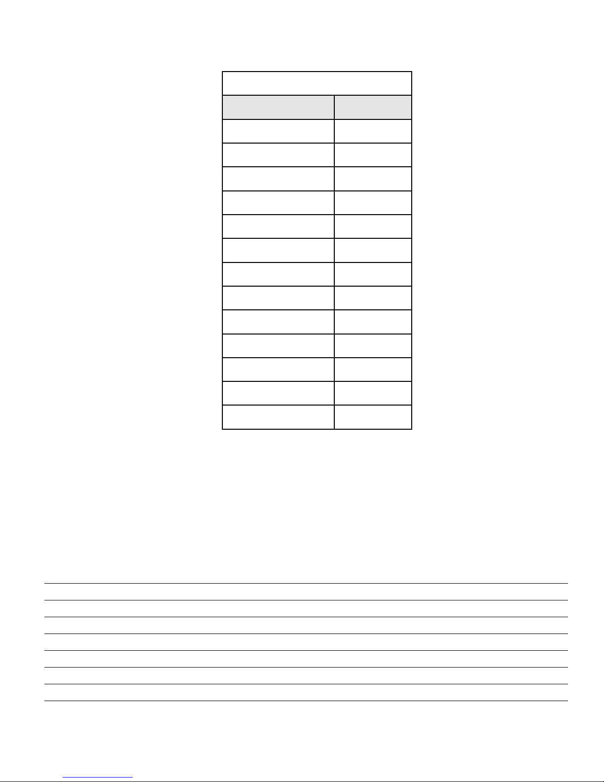
odels covered in this manual
M
Model number Voltage
SHKA4000 (4320) 120V
SHKA4000-1CE (4321) 220-240V
SHKA4000-5 (4322) 120V
SHKA4000-6CE (4323) 220-240V
SHKA4000-7 (4338) 120V
SHKA4000-8CE (4339) 220-240V
SHKE4000 (4328) 120V
SHKE4000-1CE (4329) 220-240V
SHKE4000-5 (4330) 120V
Preface
SHKE4000-6CE (4331) 220-240V
SHKE4000-7 (4342) 120V
SHKE4000-7JPN (4343) 100V
SHKE4000-8CE (4344) 220-240V
MANUAL NUMBER 057-287-00 (7004342)
16 40722 7/10/17 Added gas springs section to Maitinence bpg
15 41343 5/02/17 Added F-Gas statement, removed declaration of certification bpg
14 40673 4/20/17 Updated voltage information bpg
13 40453 9/13/16 Circuit breaker P/N in Replacement Parts from 330-250 & 330-399 to 330-138-00 ccs
12 40139 4/15/15 Updated warranty information ccs
11 31361 7/18/14 Removed CE reference from pg 2-5 ccs
10 31164/OS-775 7/9/14 Added care and cleaning of acrylic lid to Section 3 ccs
9 30954 4/10/14 Updated Setting TImer for Continuous Shaking Step 3 - pg 5-6 ccs
Thermo Scientific
Incubated and Refrigerated Shakers i
Page 3

Preface
Contains Parts and Assemblies
Susceptible to Damage by
E
lectrostatic Discharge (ESD)
CAUTION
Preface
Important Read this instruction manual. Failure to read, understand and follow the instructions in this manual
may result in damage to the unit, injury to operating personnel, and poor equipment performance.
s
Caution All internal adjustments and maintenance must be performed by qualified service personnel. s
Material in this manual is for information purposes only. The contents and the product it describes are subject
to change without notice. Thermo Fisher Scientific makes no representations or warranties with respect to this
manual. In no event shall Thermo be held liable for any damages, direct or incidental, arising out of or related to
the use of this manual.
©2010 Thermo Fisher Scientific. All rights reserved.
Thermo Scientificii Incubated and Refrigerated Shakers
Page 4

Preface
Important operating and/or maintenance instructions. Read the accompanying text carefully.
Potential electrical hazards. Only qualified persons should perform procedures associated with this
symbol.
Equipment being maintained or serviced must be turned off and locked off to prevent possible injury.
Hot surface(s) present which may cause burns to unprotected skin, or to materials which may be
damaged by elevated temperatures.
WEEE Compliance: Thermo Fisher Scientific has contracted with companies for recycling/disposal in
each EU Member State. For further information, send an email to weee.recycle@thermofisher.com.
4 Always use the proper protective equipment (clothing, gloves, goggles, etc.)
4 Always dissipate extreme cold or heat and wear protective clothing.
4 Always follow good hygiene practices.
4 Each individual is responsible for his or her own safety.
Thermo Scientific
Incubated and Refrigerated Shakers iii
Page 5

Preface
Do You Need Information or Assistance on
Thermo Scientific Products?
If you do, please contact us 8:00 a.m. to 6:00 p.m. (Eastern Time) at:
1-740-373-4763 Direct
1-800-438-4851 Toll Free, U.S. and Canada
1-877-213-8051 FAX
http://www.thermofisher.com Internet Worldwide Web Home Page
service.led.marietta@thermofisher.com Tech Support Email Address
Certified Service Web Pagewww.unitylabservices.com
Our staff can provide information on pricing and give you quotations. We canSales Support
take your order and provide delivery information on major equipment items or make
arrangements to have your local sales representative contact you. Our products are listed on the
Internet and we can be contacted through our Internet home page.
Our staff can supply technical information about proper setup, operation orService Support
troubleshooting of your equipment. We can fill your needs for spare or replacement parts or
provide you with on-site service. We can also provide you with a quotation on our Extended
Warranty for your Thermo Scientific products.
Whatever Thermo Scientific products you need or use, we will be happy to discuss your
applications. If you are experiencing technical problems, working together, we will help you
locate the problem and, chances are, correct it yourself...over the telephone without a service
call.
When more extensive service is necessary, we will assist you with direct factory trained
technicians or a qualified service organization for on-the-spot repair. If your service need is
covered by the warranty, we will arrange for the unit to be repaired at our expense and to your
satisfaction.
Regardless of your needs, our professional telephone technicians are available to assist you
Monday through Friday from 8:00 a.m. to 6:00 p.m. Eastern Time. Please contact us by
telephone or fax. If you wish to write, our mailing address is:
Thermo Fisher Scientific (Asheville) LLC
401 Millcreek Road, Box 649
Marietta, OH 45750
International customers, please contact your local Thermo Scientific distributor.
Thermo Scientificiv Incubated and Refrigerated Shakers
Page 6

Table of Contents
Section 1
Section 2
Section 3
Section 4
Section 5
Safety Information . . . . . . . . . . . . . . . . . . . . . . . . . . . . . . . . . . . . . . . . . . . . 1-1
General Specifications . . . . . . . . . . . . . . . . . . . . . . . . . . . . . . . . . . . . . . . 2-1
Control Panels . . . . . . . . . . . . . . . . . . . . . . . . . . . . . . . . . . . . . . . . . . . . . . . 3-1
A-Class Control Panel Features . . . . . . . . . . . . . . . . . . . . . . . . . . . . . 3-1
E-Class Control Panel Features . . . . . . . . . . . . . . . . . . . . . . . . . . . . . 3-2
Unpacking and Installation . . . . . . . . . . . . . . . . . . . . . . . . . . . . . . . . . . . . 4-1
Location . . . . . . . . . . . . . . . . . . . . . . . . . . . . . . . . . . . . . . . . . . . . . . .4-1
Unpacking . . . . . . . . . . . . . . . . . . . . . . . . . . . . . . . . . . . . . . . . . . . . . 4-1
Platform Installation . . . . . . . . . . . . . . . . . . . . . . . . . . . . . . . . . . . . . 4-2
Electrical Requirements . . . . . . . . . . . . . . . . . . . . . . . . . . . . . . . . . . . 4-2
Test Tube Rack Installation . . . . . . . . . . . . . . . . . . . . . . . . . . . . . . . . 4-3
Flask Clamp Installation . . . . . . . . . . . . . . . . . . . . . . . . . . . . . . . . . . 4-3
Operation . . . . . . . . . . . . . . . . . . . . . . . . . . . . . . . . . . . . . . . . . . . . . . . . . . . .5-1
A-Class . . . . . . . . . . . . . . . . . . . . . . . . . . . . . . . . . . . . . . . . . . . . . . . .5-1
Temp Controller -Setting Temperature . . . . . . . . . . . . . . . . . . . . . . . 5-2
Temperature Calibration . . . . . . . . . . . . . . . . . . . . . . . . . . . . . . . . . . 5-3
E-Class . . . . . . . . . . . . . . . . . . . . . . . . . . . . . . . . . . . . . . . . . . . . . . . .5-4
Temperature Calibration . . . . . . . . . . . . . . . . . . . . . . . . . . . . . . . . . . 5-5
AC Power Loss . . . . . . . . . . . . . . . . . . . . . . . . . . . . . . . . . . . . . . . . . .5-5
Setting Operating Temperature . . . . . . . . . . . . . . . . . . . . . . . . . . . . . 5-5
Setting Timer for Continuous Shaking . . . . . . . . . . . . . . . . . . . . . . . 5-6
Setting Timer for Timed Shaking . . . . . . . . . . . . . . . . . . . . . . . . . . . 5-6
RS232 Communication Configuration . . . . . . . . . . . . . . . . . . . . . . . 5-7
RS232 Interface Port . . . . . . . . . . . . . . . . . . . . . . . . . . . . . . . . . . . . . 5-7
Setting High-Limit Control . . . . . . . . . . . . . . . . . . . . . . . . . . . . . . . . 5-8
Optional Refrigeration System . . . . . . . . . . . . . . . . . . . . . . . . . . . . . . 5-9
Setting Low-Limit Control (Refrigerated) . . . . . . . . . . . . . . . . . . . . . 5-9
Optional Refrigeration System . . . . . . . . . . . . . . . . . . . . . . . . . . . . 5-10
Defrost Timer . . . . . . . . . . . . . . . . . . . . . . . . . . . . . . . . . . . . . . . . . 5-11
Incubated and Refrigerated Shakers vThermo Scientific
Page 7

Table of Contents
Section 6
Section 7
Section 8
Maintenance . . . . . . . . . . . . . . . . . . . . . . . . . . . . . . . . . . . . . . . . . . . . . . . . 6-1
Gas Springs . . . . . . . . . . . . . . . . . . . . . . . . . . . . . . . . . . . . . . . . . . . . 6-1
Platform Mounting Plate . . . . . . . . . . . . . . . . . . . . . . . . . . . . . . . . . . 6-1
Platform Maintenance . . . . . . . . . . . . . . . . . . . . . . . . . . . . . . . . . . . . 6-2
For A-Class Series Only . . . . . . . . . . . . . . . . . . . . . . . . . . . . . . . . . . . 6-3
Care and Cleaning of Acrylic Lid . . . . . . . . . . . . . . . . . . . . . . . . . . . . 6-3
Troubleshooting . . . . . . . . . . . . . . . . . . . . . . . . . . . . . . . . . . . . . . . . . . . . . .7-1
Replacement Parts . . . . . . . . . . . . . . . . . . . . . . . . . . . . . . . . . . . . . . . . . . . 8-1
Ordering Procedures . . . . . . . . . . . . . . . . . . . . . . . . . . . . . . . . . . . . . 8-3
vi Incubated and Refrigerated Shakers Thermo Scientific
Page 8

Section 1 Safety Information
This manual contains important operating and safety information. The
user must carefully read and understand the contents of this manual prior
to the use of this equipment.
Your Thermo Scientific MaxQ 4000 Shaker has been designed with
function, reliability, and safety in mind. It is your responsibility to install
it in conformance with local electrical codes. For safe operation, pay
attention to Notes, Cautions, Warnings throughout the manual.
Warnings
To avoid electrical shock, always:
1. Use a properly grounded electrical outlet of correct voltage and current
handling capacity.
2. Disconnect from the power supply prior to maintenance and servicing.
To avoid personal injury:
1. Do not use in the presence of flammable or combustible materials; fire
or explosion may result. This device contains components which may
ignite such materials. Not rated for use in hazardous atmospheres.
2. Wear appropriate eye and hand protection when handling hazardous
chemicals.
3. Refer servicing to qualified personnel.
4. Do not modify construction and/or assembly of equipment.
5. Do not remove tags, labels, decals, or other information from the unit.
6. Stand clear of equipment when it is operating.
7. If shaking action will result in the evolution of gases or fumes, carry
out the operation in a well-ventilated laboratory hood.
Incubated and Refrigerated Shakers 1-1Thermo Scientific
Page 9

Section 1
Safety Information
To avoid personal injury (continued):
8. Use equipment only for its intended purpose. Use only the accessories
and attachments that are shipped with the equipment or are specified
for it. Substituting other attachments or accessories can produce
hazards or make the unit inoperative.
9. Perform regular maintenance service as specified in this manual and
keep unit in good repair. Do not operate with known defects.
10. Do not use the shaker to mix flammable materials or where the
transfer of mechanical energy to glass could cause glass breakage.
1-2 Incubated and Refrigerated Shakers Thermo Scientific
Page 10
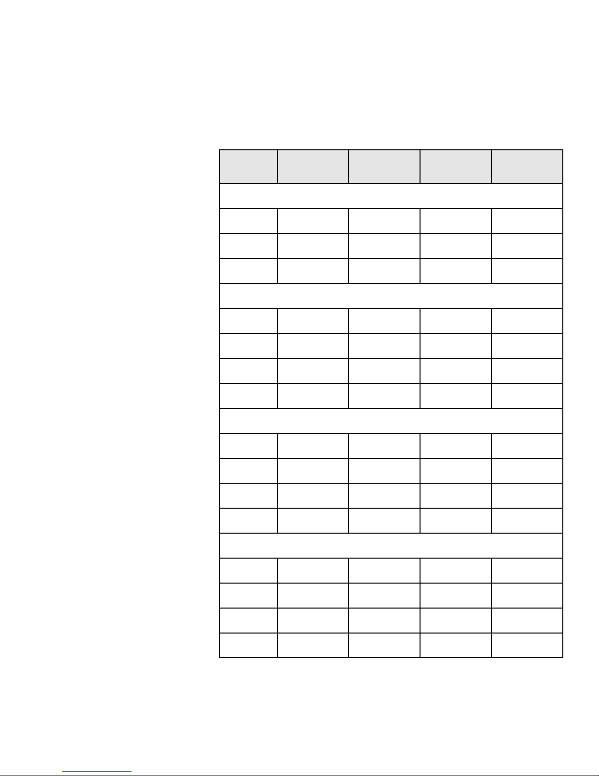
Section 2 General Specifications
Model
number
Exterior Unit Dimensions
Length 32” (81.3 cm) 32” (81.3 cm) 32” (81.3 cm) 32” (81.3 cm)
Width 22.5” (57.2 cm) 22.5” (57.2 cm) 22.5” (57.2 cm) 22.5” (57.2 cm)
Height 22” (55.9 cm) 22” (55.9 cm) 22” (55.9 cm) 22” (55.9 cm)
Electrical - Standard Temperature
Voltage AC 120 220-240 120 220-240
Amperage 5.0 3.0 5.0 2.5
Wattage 625 725 625 625
Frequency 60 50/60 60 50/60
High Temperature
All Analog
“A” Series units
All Analog
“A” Series units
All Digital
“E” Series units
All Digital
“E” Series units
Voltage AC 120 220-240 120 220-240
Amperage 9.0 5.0 9.0 4.5
Wattage 1100 1200 1100 1100
Frequency 50/60 50/60 50/60 50/60
Refrigerated
Voltage AC 120 220-240 120 220-240
Amperage 14.0 7.0 14.0 7.0
Wattage 1500 1500 1500 1500
Frequency 60 50 60 50
Incubated and Refrigerated Shakers 2-1Thermo Scientific
Page 11

Section 2
General Specifications
Model number
peed Accuracy
S
Timer
Display
Mutable Alarms None None
Motor Permanent Magnet DC Permanent Magnet DC Solid State Brushless DC Solid State Brushless DC
All Analog
A” Series units
“
0 to 400 rpm, ±10 rpm
4
Continuous or timed opera-
tion from 1-60 min.
3 individual LED displays
indicate temperature in 1°C
increments. Analog
tachometer displays speed
in rpm.
All Analog
A” Series units
“
0 to 400 rpm, ±10 rpm
4
Continuous or timed opera-
tion from 1-60 min.
3 individual LED displays
indicate temperature in 1°C
increments. Analog
tachometer displays speed
in rpm.
All Digital
E” Series units
“
5 to 500 rpm, ±1 rpm
1
Continuous or timed operation
0.1-999 hours or 0.1-999 mins.
3 individual LED displays indicate temperature, time and
speed simultaneously. 3 characters height 1/2 inch (1.27 cm)
Audible portion of the alarm
can be silenced for a period of
1 hour without deactivating the
actual alarm condition by
depressing any key.
All Digital
E” Series units
“
5 to 500 rpm, ±1 rpm
1
Continuous or timed operation
0.1-999 hours or 0.1-999 mins.
3 individual LED displays indicate temperature, time and
speed simultaneously. 3 characters height 1/2 inch (1.27 cm)
Audible portion of the alarm can
be silenced for a period of 1
hour without deactivating the
actual alarm condition by
depressing any key.
Soft Start Feature None None
RS232 Interface * None None
Recorder Output * None None
Intended Use
Orbital shakers are designed to provide increased aeration in a stable
temperature environment.
Unintended Use
1) Not intended for use in Class I or II applications as defined in 21 CFR
2) Not intended for mixtures of flammable materials
Software algorithms prevent
sudden start/stops.
Monitor speed, temperature in
°C and time with a computer.
10 mv/°C output monitors temperature with external chart
recorder.
Software algorithms prevent
sudden start/stops.
Monitor speed, temperature in
°C and time with a computer.
10 mv/°C output monitors temperature with external chart
recorder
2-2 Incubated and Refrigerated Shakers Thermo Scientific
Page 12

Section 2
General Specifications
Model number
peed
S
All Analog
A” Series units
“
one
N
All Analog
A” Series units
“
one
N
Speed Shut off None None
Timer None None
Unbalanced Load None None
All Digital
E” Series units
“
Audible with flashing
LED indicate when
speed deviates more
than 10% of set point.
When speed deviates
10% of set point, unit
will shut down immediately.
Beeps twice when
time has expired.
Shaking motion stops.
If the unit is running
in an unbalanced condition, an alarm will
sound and the shaker
will stop until the end
user corrects the condition. The speed display
will flash “bAL” on
speed panel LED.
All Digital
E” Series units
“
Audible with flashing
LED indicate when
speed deviates more
than 10% of set point
When speed deviates
10% of set point, unit
will shut down immediately.
Beeps twice when
time has expired.
Shaking motion stops.
If the unit is running
in an unbalanced condition, an alarm will
sound and the shaker
will stop until the end
user corrects the condition. The speed display
will flash “bAL” on
speed panel LED.
Optional Platform Dimensions - in. (cm)
Catalog Number L xW
30110 Universal 18” x 18” (45.7 x 45.7 cm)
Incubated and Refrigerated Shakers 2-3Thermo Scientific
Page 13

Section 2
General Specifications
The MaxQ 4000 series of bench top, incubated and refrigerated shakers
are available in either analog or digital control configurations:
• A-Class shakers: SHKA4000, SHKA4000-1CE, SHKA4000-5,
SHKA4000-6CE, SHKA4000-7, SHKA4000-8CE: control
temperature by a Proportional/Integral/Derivative (PID)
microprocessor-based controller. Solid-state control maintains time and
speed and is adjustable with rotary dials. Analog tachometer displays
speed in RPM, verifying accuracy of speed setting. Refrigerated units
feature environmentally safe CFC free insulation and coolant.
• E-Class shakers: SHKE4000, SHKE4000-1CE, SHKE4000-5,
SHKE4000-6CE, SHKE4000-7, SHKE4000-8CE: control
temperature, time and speed by a Proportional/Integral/Derivative
(PID) microprocessor-based controller that is adjustable with switches
on a keypad in 1 rpm increments. Refrigerated units feature
environmentally safe CFC free insulation and coolant. Flashing display
indicates power interruption. Pressing any key will clear display. Nonvolatile memory maintains speed and time set points in the event of a
power interruption. Speed and time set points are automatically
reactivated after power is restored.
• Temperature range and accuracy follow. All units have a uniformity of
±0.5°C at 37°C in flask:
Standard Temperature: SHKA4000, SHKA4000-1CE, SHKE4000,
SHKE4000-1CE,
10°C above ambient to 60°C, ±0.1°C at 37°C in flask.
High Temperature: SHKA4000-5, SHKA4000-6CE, SHKE4000-5,
SHKE4000-6CE,
10°C above ambient to 80°C, ±0.1°C at 37°C in flask.
Refrigerated: SHKA4000-7, SHKA4000-8CE, SHKE4000-7,
SHKE4000-8CE,
15°C below ambient to 60°C, ±0.1°C at 37°C in flask. Refrigeration
system needs to be turned off whenever the set point is at or above
32°C.
2-4 Incubated and Refrigerated Shakers Thermo Scientific
Page 14

Section 2
General Specifications
In addition, all versions offer:
• Space efficient tubular heaters.
• Drive interrupt halts shaking action when lid is opened.
• All set points are retained by non-volatile memory that automatically
reactivates after power is restored.
• Visual, user adjustable over-temperature safety signal with independent
thermostat controls the heat if main controller fails.
• 3/4 inch (1.9 cm) triple eccentric orbital drive.
• 6 permanently lubricated ball bearings.
• 50 lb (22.7 kg) platform load capacity at safe speeds less than 400 rpm
for A-Class shakers and less than 500 rpm for E-Class shakers.
Environmental Operating Conditions
Pollution Degree 2**
Installation Category II**
Altitude . . . . . . 2000 meters MSL (Mean Sea Level)
Relative Humidity . . .20% to 80% maximum, non-condensing
Electrical Supply . . . . . . . . . . 120 VAC or 240 VAC
Voltage Tolerance . . . . . . +10% of normal rated line
Temperature . . . . . . . . . . . . . . . . . . . . 15°C to 32°C
Product Usage . . . . . . . . . . . . . . . . . Indoor use only
**Refer to IEC 664-1
Caution Operation of the shaker in a CO2 enriched atmosphere is not
recommended. The formation of carbonic acid could cause electrical
failures.
s
Incubated and Refrigerated Shakers 2-5Thermo Scientific
Page 15

Section 2
General Specifications
Fluorinated Greenhouse Gases
Compliant with REGULATION (EU) No 517/2014 OF THE EUROPEAN
PARLIAMENT AND OF THE COUNCIL on fluorinated greenhouse gases.
This product contains fluorinated greenhouse gases in a hermetically sealed
system. If a leak in the sealed system is detected, the operator shall repair
without undue delay.
The following model is designed for use with the following amounts of fluorinated greenhouse gases:
Model Refrigerant Amount (kg) GWP
SHKE4000-8CE R-134a 0.227 1430
Declaration of Conformity
Copies of the Declaration of Conformity are available upon request.
2-6 Incubated and Refrigerated Shakers Thermo Scientific
Page 16

Section 3 Control Panels
Figure 3-1. A-Class Control Panel
A-Class Control Panel
Features
1. Temperature Controller: Maintains chamber temperature.
2. Temperature Switch: Activates heater-allowing controller to maintain
temperature.
3. Temperature High-Limit Light: Illuminates when high limit
thermostat is controlling chamber temperature.
4. Speed Control: Sets platform rotation speed.
5. Power Switch: Turns power on and off to shaker.
6. Speed Tachometer: Analog display of platform rotation speed.
7. Time(r): Allows user to choose either continuous or timed operation.
Incubated and Refrigerated Shakers 3-1Thermo Scientific
Page 17

Section 3
Control Panel Operation
l
e
n
a
P
l
o
r
t
n
Co
s
s
a
Cl
-
E
.
2
-
3
e
gur
i
F
E-Class Control Panel
Features
1. Speed Display: 3 digit LED indicates actual or set point speed
2. Up Arrow Key: Increases platform rotation speed
3. Down Arrow Key: Decreases platform rotation speed
4. Speed Light: Red light Illuminates when a locked rotor or over-speed
condition exists
5. RPM Light: Illuminates to indicate actual speed
6. Set RPM Light: Illuminates when speed is being set
7. Stop Switch: Stops platform rotation
8. Start Switch: Starts platform rotation
9. Power Switch: Turns power on and off to shaker
10. Up Arrow key: Increases shaking time
3-2 Incubated and Refrigerated Shakers Thermo Scientific
11. Down Arrow key: Decreases shaking time
12. Time(r) Display: 3 digit LED indicates time remaining or elapsed time
13. Set Time: Illuminates when time is being set
14. Timer/Elapsed: Allows the user to choose elapsed time operation,
elapsed, or timed operation, timer.
15. Hours/Minutes Switch: Allows user to choose timing operation in
either hours or minutes
Page 18

Section 3
Section title
E-Class Control Panel
Features (continued)
16. Minutes: Timer indicates minutes
17. Hours: Timer indicates hours
18. Elapsed Timer Light: Indicates accumulated time
19. Temperature Display: 3 digit LED indicates chamber temperature
20. Up Arrow Key: Increases temperature
21. Down Arrow Key: Decreases temperature
22. High-Limit Light: Indicates high-limit control has been activated
23. Water Light: This display has no function on this unit
24. Heat On Light: Indicates heaters are energized
25. Set Temp Light: Indicates temperature can be set
26. Heat On Switch: Turns on heat
27. Heat Off Switch: Turns off heat
Incubated and Refrigerated Shakers 3-3Thermo Scientific
Page 19

Section 4 Unpacking and Installation
The shipping carton should be inspected upon delivery. When received,
carefully examine for any shipping damage before unpacking. If damage is
discovered, the delivering carrier should specify and sign for the damage on
your copy of the delivery receipt.
Open the carton carefully making certain that all parts are accounted for
before packaging materials are discarded. After unpacking, if damage is
found, promptly report it to the carrier and request a damage inspection
properly.
Important Failure to request an inspection of damage within a few days
after receipt of shipment absolves the carrier from any liability for damage.
Call for a damage inspection promptly.
Unpacking
Location
Use the packing list below when unpacking to verify that the complete
unit has been received. Do not discard packing materials until all is
accounted for.
The following items are included in the shipment:
Inspection Tag- 528-028-00
Mounting Plate Mat- 790-316-13
Thumbscrew Knob (4) - 562-184-10
Male Connector (E-class only)- 420-359-00
If any items are missing, contact Technical Services.
Put the shaker on a level table or bench capable of supporting the weight
of the shaker with any accessories while in operation. Place shaker near an
electrical outlet that matches the unit nameplate requirements. Allow
approximately 2” (5 cm) of clearance around the unit for free air
convection, accessory attachments and user convenience. Shakers with
refrigeration should be placed near an accessible drain. Route the drainage
tube on the back of the unit to this drain.
Incubated and Refrigerated Shakers 4-1Thermo Scientific
Page 20

Section 4
Unpacking and Installation
Electrical
Requirements
SHKA4000 and SHKE4000 Series shakers require a 120VAC, 60 Hz
power source. They are supplied with a 3-wire line cord and should be
plugged into an outlet designed for 3-prong plugs. If an extension cord is
used, it also should be the 3-wire grounded type. For an outlet designed to
accept 2-prong plugs (ungrounded), it is required that a qualified
electrician replaces the outlet with a new, grounded type.
SHKA4000-1CE and SHKE4000-1CE Series shakers require a 220240VAC, 50/60 Hz power source. Power cords are supplied.
If a plug must be installed, use only the 3-prong grounded type, rated for
the unit load requirements and matching the power outlet. Make sure the
green ground wire is secured to the plug ground terminal.
To eliminate hazard of electrical shock, make sure floor around shaker is
dry. In the event of accidental spilling or splashing of liquids, clean up
and/or neutralize the spilled liquids before continuing.
Disconnect the shaker from the power source when not in use.
Warning Do not operate shaker with a damaged electrical cord.
s
Platform Installation
1. Select the appropriate platform for the vessels to be shaken. A wide
variety of platforms and accessories are available:
• Dedicated platforms have the maximum number of flask clamps
attached for safe operation.
• Combination platforms allow the user to shake a wide variety of
different sized vessels on the same platform.
2. Carefully position the platform horizontally over the shaker’s mounting
plate, aligning the 4 mounting holes.
3. Position one of the thumbscrews provided through each of the 4platform mounting holes and tighten securely.
Caution Do not operate shaker with an unbalanced load. Platforms should
be loaded for optimum stability and operation. Do not lift shaker by the
platform.
s
4-2 Incubated and Refrigerated Shakers Thermo Scientific
Page 21

Section 4
Unpacking and Installation
Flask Clamp
Installation
Each flask clamp contains a support spring located at the narrow top of
the clamp.
Depending on the size of the clamp, the clamp base may contain one or
several screws necessary to secure the clamp to the platform. All screws
provided with the clamp must be properly attached to the platform.
1. Carefully place the desired vessel in the clamp by first pulling the
clamp spring far enough apart to enable the flask base to be positioned
inside the clamp. Gently slide the flask into its proper position
securing it to the wider bottom of the clamp. The spring will hold the
neck of the flask securely in place and provide security during shaking.
2. Make sure all vessels are securely clamped before turning on unit.
Wherever possible, vessels should contain a stopper to prevent hazardous
substances being thrown out during the mixing action.
Warning Do not operate the shaker at speeds that will cause the contents
of vessels to be thrown out.
s
Test Tube Rack
Installation
1. Position the test tube rack on the combination platform so that the
cutouts on the rack’s outside bottom are aligned with corresponding
mounting holes on the platform. There are two cutouts on each side of
the rack.
2. Secure the rack to the platform with mounting screws provided with
the rack.
Incubated and Refrigerated Shakers 4-3Thermo Scientific
Page 22

Section 5 Operation
A-Class
Refer to Section 3 for control panel reference.
Power Switch
1. Depress top portion of power switch to turn on shaker.
2. Depress bottom portion of power switch to turn off shaker.
Caution It is recommended that shaking action be started at a low speed in
order to check that all vessels are secure and that no spilling of contents
will occur.
Speed Control and Display
1. Slowly rotate the knob on the solid-state speed control clockwise to
increase speed and counterclockwise to decrease speed. The markings
on the outside of the dial are for reference purposes only.
2. The speed control tachometer provides an analog readout of the actual
platform rotation speed up to a maximum of 400 rpm.
s
Time(r)
1. From the 12 o’clock off position, rotate timer knob counterclockwise
to the ON position to initiate continuous operation.
2. For timed operation, rotate timer knob clockwise from 1 minute to 60
minutes. The markings on the side of the dial are in 5-minute
increments.
Note Shaker will not operate if the timer is in the Off position.
Incubated and Refrigerated Shakers 5-1Thermo Scientific
Page 23

Section 5
Operation
Temp Controller -
Setting Temperature
Refer to Figure 5-1 for control panel reference.
Figure 5-1. Temperature Controller
1. CONTROLLER SELF-TEST: When the shaker is powered up, the
controller will display 8888 along with the three decimal points and
the HEAT ON indicator lamp. The display will then blank out for 2
seconds before showing the chamber temperature.
2. HEAT ON INDICATOR: The HEAT ON indicator lamp is lit when
the chamber heaters are receiving power. The lamp will normally flash
when the chamber temperature is at set point.
3. SET POINT ADJUSTMENTS: The temperature controller normally
displays the chamber temperature.
Press Controller
*
* s
* t
View set point
Decrease set point
Increase set point
To view or change the temperature set point, proceed as follows:
a. Press and hold the “star” (*) key and use either the up or down
arrow key to adjust the set point to the desired temperature.
Release the “star” (*) key.
b. Allow sufficient time for chamber temperature to stabilize.
5-2 Incubated and Refrigerated Shakers Thermo Scientific
Page 24

Section 5
Operation
Temperature
Calibration
1. Fill a 250-ml Erlenmeyer flask with approximately 100ml of water and
position it at the approximate geometric center of the shaking
platform.
2. Install a thermocouple inside the flask with the thermocouple junction
in direct contact with the water.
3. Press and hold the “star” (*) key and using the up or down arrow key,
adjust the set point to the desired temperature.
4. Allow the shaker to run until chamber temperature has stabilized.
5. The controller display should now be indicating the set point
temperature. Make note of the thermometer reading.
6. Press and hold both arrow keys until the controller display indicates
“tunE”. Release the arrow keys. Press and release the down arrow key,
the display should now alternate between “LEUL” and “1”. Press and
hold the “star” (*) key and using the up arrow key adjust the display to
read “3”. Release the “star” (*) key. The display should now alternate
between “LEUL” and “3”. Press and release the up arrow key until the
display indicates “Zero”. The display should now alternate between
“Zero” and a numerical value.
Thermometer = 60°C
7. Using the examples shown in the table
at right and the thermometer value
obtained in Step 5 above, enter the
correct “Zero” value into the controller
by pressing the “star” (*) key and using
the up or down arrow key. If there is
already a “Zero” value present, then add
the new value to the one already
present.
Controller Reading = 65°C
Subtract = -5°C
Enter Zero value of -5°C
Thermometer = 70°C
Controller Reading = 65°C
Subtract = +5°C
Enter Zero value of +5°C
8. When the correct “Zero” value has been entered, press and hold the
two arrow keys together until the display again indicates the chamber
temperature. If the procedure was done correctly, the controller display
should now agree with the thermometer reading to within ±0.5°C.
9. Allow the unit to run for at least an additional 30 minutes.
10. Re-check the thermometer reading. The controller display and the
thermometer should agree to within ±0.5°C. If not, repeat Steps 6, 7
and 8.
Incubated and Refrigerated Shakers 5-3Thermo Scientific
Page 25

Section 5
Operation
E-Class
Refer to Section 3 for control panel reference.
Turning Shaker On
Begin with the shaker power off.
1. Press power switch once (I) to turn on shaker.
2. Press power switch a second time (O) to turn off shaker.
Note There will be a 3 second delay from the time power is turned On to
the time the shaker is activated. Control panel will illuminate when shaker
power is activated. An audible tone will sound before the display lights.
Setting Shaking Speed
1. Hold down appropriate arrow key in the speed module of the control
panel, up or down, until desired speed is set up to 500 rpm. SET RPM
light will illuminate.
2. Press START switch to begin shaking. RPM light will illuminate.
3. Press STOP switch to end shaking. SET RPM light will illuminate.
Note Speed can be changed without pressing the start or stop switches.
Simply press the appropriate up or down key until desired rpm is reached.
An audible tone will sound before the display lights.
Calibrating Shaking Speed
1. Choose a speed for which calibration is desired by using the shaker’s
up or down arrow keys.
2. Measure current shaker speed by using a digital hand-held tachometer.
3. If the tachometer reading matches the shaker display, no calibration is
necessary. If the tachometer reading is different from the shaker’s
display, then calibration is required.
4. To get into Calibration mode, hold down the START key, press and
release the STOP key, then release the START key.
5. The decimal point on the SPEED display will flash, indicating
Calibration mode.
6. Use the up or down arrow keys to set the shaker speed to match the
tachometer’s readout.
5-4 Incubated and Refrigerated Shakers Thermo Scientific
7. Press STOP key to enter the new speed value.
8. Press START key to exit Calibration mode.
Page 26

Section 5
Operation
Setting Operating
Temperature
AC Power Loss
1. Press and hold up arrow key to increase temperature, release key when
desired set point is obtained.
2. Press and hold down arrow key to decrease temperature, release key
when desired set point is obtained.
3. Once set, temperature control is initiated by pressing the heat on
button; the heater will react and start increasing the temperature to
reach the set point.
4. During operation, both the up and down arrow keys can be used to
adjust the temperature to a new set point.
The operating microprocessor possesses a non-volatile memory. Upon
resumption or recovery from an AC power loss, the following will be
noted:
• All readouts will flash until any key is pressed.
• If unit was shaking at the time of power failure, it will resume
operation at the speed and timer settings that were entered at the time
that AC power failed.
Temperature
Calibration
1. Fill a 250-ml Erlenmeyer flask with approximately 100 ml of water
and position it at the approximate geometric center of the shaking
platform.
2. Install a thermocouple inside the flask with the thermocouple junction
in direct contact with the water.
3. Adjust the safety thermostat to its maximum clockwise position.
4. Using the up and down keys, adjust the set point temperature to read
37ºC or any other desired set point.
5. Allow sufficient time for chamber temperature to stabilize.
6. Press HEAT ON button and, while continuing to hold, press and
release the HEAT OFF button. Now, release the HEAT ON button.
7. The decimal point should now be flashing indicating Calibration
mode.
Incubated and Refrigerated Shakers 5-5Thermo Scientific
Page 27

Section 5
Operation
Temperature
Calibration (cont.)
Setting Timer for
Timed Shaking
8. Use the up and down arrow keys to adjust the temperature on LED
readout to match the temperature reading on the thermocouple meter.
9. Press the HEAT OFF button. The beeper will sound indicating that
the new calibration value just added is now stored in the nonvolatile
memory of the temperature controller.
10. Press HEAT ON button twice to complete return to normal operating
mode.
Note It is important to press the HEAT OFF button to exit Calibration
mode.
1. Press TIMER/ELAPSED switch until TIMER and SET TIME lights
are illuminated. The HOURS or MINUTES light will also light up at
this point, depending on which option was previously chosen.
2. Press HOURS/MINUTES switch for desired timing mode.
Setting Timer for
Continuous Shaking
3. Hold down appropriate arrow switch in the TIME module of the
control panel, up or down, until desired timing cycle is set from 0.1
hour up to 999 hours, or from 0.1 minute to 999 minutes depending
on which timing mode is chosen. SET TIME light will illuminate.
4. Press START to begin timed shaking; countdown will begin from time
set. TIMER and MINUTES or HOURS lights will illuminate and
timer will count down from time selected. An audible alarm will sound
at the end of the timing cycle and platform rotation will cease.
1. Press TIMER/ELAPSED membrane switch until ELAPSED light is
illuminated. The HOURS or MINUTES light will also light up at this
point depending on which option was previously chosen.
2. Press HOURS/MINUTES membrane switch for desired timing mode.
3. TIME display should show 000. Press START to begin timed shaking.
Timer will begin to count up and will display accumulated time in
display window. Platform rotation will continue until operator presses
the Stop button. The TIME display will flash when ELAPSED time
reaches 999 minutes or 999 hours.
5-6 Incubated and Refrigerated Shakers Thermo Scientific
Page 28

Section 5
Operation
RS232 Interface Port
RS232 Communication
Configuration
The RS232 interface port is located on the left side rear of the shaker
cabinet and requires the use of a laptop or desk top computer running
Microsoft Windows 98 or newer operating system.
Figure 5-2. RS232 Interface Port
Note The following paragraphs detail the step-by-step procedures for
configuring Microsoft® Hyperterminal running on a host computer using
Windows® XP. These instructions may need to be modified to be used
with a different terminal emulator program and/or operating system.
Contact Technical Services if further assistance is required.
1. Power up the host computer and close any running applications.
2. Open the HyperTerminal application by clicking on “Start” \
“Programs” \ “Accessories” \ “Communications” \ “HyperTerminal.”
3. In the “Connection Description” box, enter the name “Max Q Shaker”
and choose an icon and click “OK.”
4. In the “Connect To” box, verify that “COM1” is selected under
“Connect Using.” Click “OK.”
5. In the “COM1 Properties” box \ “Port Settings” folder select the
following options:
Bits per second: . . . . . . . . . . . . . . . . . . . . 19200
Data bits: . . . . . . . . . . . . . . . . . . . . . . . . . . . . . 8
Parity: . . . . . . . . . . . . . . . . . . . . . . . . . . . . None
Stop bits: . . . . . . . . . . . . . . . . . . . . . . . . . . . . . 1
Flow control . . . . . . . . . . . . . . . . . . . . . . . None
After verifying the above settings, click “OK.”
6. In the main dialog box click on “File” \ “Save.”
7. Exit the program by clicking on “File” \ “Exit” \ “Yes”.
8. Verify the program was saved by going to “Start” \ “Programs” \
“Accessories” \ “Communications” \ “HyperTerminal” \ “Max Q
Shaker.”
9. This completes the configuration of HyperTerminal. Go to Step 10.
Incubated and Refrigerated Shakers 5-7Thermo Scientific
Page 29

Section 5
Operation
RS232 Communication
Configuration (cont.)
Setting High-Limit
Control
10. Turn shaker off and connect computer (COM 1) to shaker (COM
PORT) with DB-9 serial printer cable.
11. Start HyperTerminal by clicking on “Max Q Shaker.”
12. Power up shaker. Shaker will screen print speed, time and temperature
at one-minute intervals.
Note RS232 Interface Port is for output only. Interface cables must not
exceed 9.8’ (3m) in length.
The high and low-limit controls are located on the right front side panel of
the shaker cabinet (Figure 5-3). The high-limit light is located on the
control panel (see Section 3).
High limit control (adjustment screw)
Low limit light
Low limit control (adjustment screw)
Figure 5-3. Control Limit Locations (Refrigerated Unit Shown)
Note Shakers without optional refrigeration system only have high-limit
control on side panel.
1. Make appropriate power connection.
2. Turn power switch ON.
3. Rotate high-limit control fully clockwise.
4. Set chamber temperature.
5. Allow sufficient time for chamber temperature to stabilize before
setting the high-limit control.
6. Rotate high-limit control slowly counterclockwise until set point is
reached.
• For A-Class shakers high-limit light will illuminate when set point is
reached. Rotate high limit control clockwise until status lamp goes out.
Make an additional 1/8 turn clockwise beyond this point.
5-8 Incubated and Refrigerated Shakers Thermo Scientific
Page 30

Section 5
Operation
Setting High-Limit
Control (continued)
Setting Low-Limit
Control (Refrigerated)
• For E-Class shakers, when set point is reached, high-limit status lamp
will flash and the audible alarm will beep once. Rotate the high-limit
control slowly clockwise approximately 1/8 turn beyond this point.
7. When desired temperature is achieved, load the shaker.
Warning Do not operate the unit if any of the temperature controls
become inoperative. A hazardous condition will develop which can result
in injury or death and property damage.
The high and low limit controls are located on the right front side panel of
the shaker cabinet. The high-limit light is located on the control panel.
Refer to Figure 5-3. The low-limit control and low limit light are available
only on units supplied with optional refrigeration system.
1. Turn ON refrigeration switch located to the left of the defrost timer
on the right rear of the shaker cabinet.
2. Rotate low-limit control fully counterclockwise.
s
3. Set chamber temperature.
4. Allow sufficient time for chamber temperature to stabilize before
setting the low-limit control.
5. Rotate low-limit control slowly clockwise. When the set point is
reached, low-limit status lamp will illuminate. Rotate the low-limit
control slowly counterclockwise until the low-limit status lamp goes
out.
6. Continue rotating the low-limit control about 5° of rotation to set it
about 1°C to 3°C below the set point, the low-limit status lamp will
extinguish and the temperature control status lamp stays lit.
7. When desired temperature is achieved, load the shaker.
Incubated and Refrigerated Shakers 5-9Thermo Scientific
Page 31

Section 5
Operation
Optional
Refrigeration System
This section applies only to units supplied with this option. The
refrigeration system on the A and E series shakers are identical in
operation. Refer to Replacement Parts for refrigeration replacement parts.
When the unit power is on, refrigeration can be initiated by turning ON
the refrigeration switch which is located to the left of the defrost timer on
the lower right side panel of the shaker cabinet. This should be initiated
(turned on) only when a temperature set point of approximately 32°C or
less is required (based on your ambient temperatures). Both the main
power switch and the refrigeration switch need to be ON for the
refrigeration system to work. When the refrigeration switch is activated,
the compressor system will run continuously and the system will go
through the following routine:
Upon every activation
of the refrigeration switch to the ON position, there
is an approximate 2-minute delay until the compressor becomes activated.
This is a safety feature, to prevent damage to the compressor in the case of
quickly switching the refrigeration switch off and on again. Because the
compressor does not turn on immediately after switching the refrigeration
switch to on, please note, THIS IS NORMAL. The defrost timer will
begin initiation. This may turn the fans off for several minutes until it
completes a normal defrost cycle.
During operation, the defrost timer will automatically “engage” every 4
hours, switching cold gas through the evaporator (inside) coils to hot gas in
order to defrost the coils. There is a dedicated sensor inside the coils which
will terminate the defrost when the temperature reaches a point where it is
assured that there is no ice or frost on the coil. At low set point
temperatures (i.e. 5°C), this defrost time will be longer than higher set
point temperatures (i.e. 25°C), which may initiate and terminate
immediately because the coils will be much warmer at higher set point
temperatures.
5-10 Incubated and Refrigerated Shakers Thermo Scientific
Page 32

Section 5
Operation
Defrost Timer
The defrost timer is located on the lower right side panel of the shaker
cabinet to the right of refrigeration power switch and is engaged whenever
the refrigeration system is turned on.
Figure 5-4. Defrost Timer
1. Refrigeration Power Switch - Activates refrigeration system, I is ON,
O is OFF.
2. Defrost Time Power Status Lamp (Power) - Timer is powered along
with refrigeration system whenever green power status lamp is lit.
3. Defrost Status Lamp (Defrost) - Cooling coil is being defrosted
whenever yellow defrost status lamp is ON. Hot gas is being bypassed
through the iced coil. When ice on the coil has melted, defrost cycle
ends automatically.
4. Fan Delay Status Lamp (Fans) - During defrost timer power-up and
after defrost cycle, the circulating fan is locked off for a 1½ minute
delay. Green fan status lamp flashes during this fan delay period.
Incubated and Refrigerated Shakers 5-11Thermo Scientific
Page 33

Section 6 Maintenance
Note The shaking mechanism is equipped with sealed ball bearings which
do not require further lubrication or adjustment.
Note Make no attempt to service or repair a Thermo Scientific product
under warranty before consulting your distributor. After the warranty
period, such consultation is still advised, especially when the repair may be
technically sophisticated or difficult.
If assistance is needed beyond what the distributor can provide, call the
Technical Services department. No merchandise, however, should be
returned without prior approval.
Wash the exterior of the unit with a soft cloth using a solution of mild
soap and water, rinse off with clean water and dry thoroughly.
Gas Springs
Replacing Platform
Mounting Plate
Warning Disconnect plug from electrical outlet before attempting any
maintenance or repair of the unit.
The gas springs should be checked periodically, and ideally every six
months. The opening force, as measured from the front lip from a closed
position, should be below 100 N (22.5 lbf) maximum. If the force is
above this value, the gas springs should be replaced. If a force
measurement is not possible, the gas springs should be replaced every two
years.
1. Remove the platform by loosening the 4 thumbscrews, remove ribbed
mat, remove the 9 smaller screws on the platform mounting plate,
there are 3 Phillips screws at each of the 3 bearing mounts. Refer to
Figure 6-1.
2. Position the platform mounting plate atop the shaker body and install
all 9 screws by hand until they are finger-tight
control fully counterclockwise (OFF) and plug the unit into an outlet.
Rotate the speed control knob slowly in the clockwise direction to
allow the shaker to orbit at its slowest speed.
s
only. Rotate the speed
Incubated and Refrigerated Shakers 6-1Thermo Scientific
Page 34

Section 6
)&!04&1 %), 1"!1
(,# %*"/
"/&+$*,2+10
-)1#,/**,2+1&+$
-)1"
%
&
$
&
%
%
&
$
$
Maintenance
Replacing Platform
Mounting Plate
(cont.)
Note While adjusting the platform retaining screws, make certain lid
switch, located at back of chamber, is activated (pressed in).
3. While it is slowly orbiting, slightly tighten each of the A screws in
Figure 1. Repeat this procedure by slightly tightening all the B screws,
then complete procedure by tightening the C screws.
Caution All screws must first be slightly tightened
to seat plate properly. s
4. Repeat the screw-tightening procedure at 50-100 RPM until all 9
screws are securely tightened.
Figure 6-1. Platform Mounting Plate
Platform
Maintenance
Suggested with every 3 months of constant use.
Caution Any internal adjustments or repairs must be performed by a
qualified service representative.
s
Remove the platform by loosening 4, thumbscrews in the platform center.
Remove the sheet metal panel (9 screws) under the platform to expose the
belt and interior parts. Inspect the drive belt for wear. Order a replacement
if necessary.
6-2 Incubated and Refrigerated Shakers Thermo Scientific
Page 35

Section 6
Maintenance
For A-Class Series
Only
Care and Cleaning of
Acrylic Lid
1. Take out the 2 motor mount screws and lift the motor out.
2. Two brushes are located under plastic caps on opposite sides of the
lower part of the motor. Unscrew the plastic caps and slide the brushes
out. Replace brushes when they are worn down to 3/16" (0.48 cm) in
length.
3. Belt tension is automatically set by the location of the motor and is
not adjustable.
4. To align a pulley, loosen the motor pulley set screws, slide the pulley
up or down into alignment then securely tighten the motor pulley set
screws.
Washing: Clean with a solution of mild soap or detergent and lukewarm
water. Use a clean soft cloth, applying only light pressure. Rinse with clean
water and blot dry with a damp cloth or chamois.
Grease, oil, or tar may be removed with a good grade of hexane, aliphatic
naphtha, or kerosene. These solvents may be obtained at a paint or
hardware store and should be used in accordance with manufacturer’s
recommendations.
Caution Do not use
or solvents such as acetone, gasoline, benzene, alcohol, carbon
tetrachloride, or lacquer thinner. These can scratch the sheet’s surface
and/or weaken the sheet causing small surface cracks called “crazing.”
Dusting: Remove dust with a soft, damp cloth or chamois. Avoid dry or
gritty cloths as they may cause surface scratches and create a static electric
charge on the surface causing dust to cling to the lid.
Polishing: Protect the lid and maintain its surface gloss by occasional
polishing with a good plastic cleaner and polish. Apply a thin, even coat
with a soft clean cloth and polish slightly with cotton flannel. Then wipe
with a damp cloth to help eliminate electrostatic charges that can attract
dust particles.
Use of proper cleaning agents: When selecting a cleaning or
decontamination agent, use the following table as a guideline.
window cleaning sprays, kitchen scouring compounds
s
Incubated and Refrigerated Shakers 6-3Thermo Scientific
Page 36

Section 6
Maintenance
Care and Cleaning of
Acrylic Lid (cont.)
Table 3-1 . Cleaning Agents
Chemical Code Chemical Code
Acetic Acid (5%) LR Hydrogen Peroxide (3%) R
Acetic Acid (Glacial) N Hydrogen Peroxide (28%) LR
Acetone N Isopropyl Alcohol (30%) LR
Ammonium Chloride R Kerosene R
Ammonium Hydroxide (10%) R Lacquer Thinner N
Ammonium Hydroxide (Conc.) R Metlhyl Alcohol (30%) LR
Aniline N Methyl Alcohol (100%) N
Battery Acid R Methyl Ethyl Ketone (MEK) N
Benzene N Methylene Chloride N
Butyl Acetate N Mineral Oil R
Calcium Chloride (Sat.) R Nitric Acid (10%) R
Calcium Hypochlorite R Nitric Acid (40%) LR
Carbon Tetrachloride LR Nitric Acid (Conc.) N
Chloroform N Oleic Acid R
Chromic Acid LR Olive Oil R
Citric Acid (10%) R Phenol Solution (5%) N
Cottonseed Oil (Edible) R Soap Solution (Mild dish soap) R
Detergent Solution (Heavy Duty) R Sodium Carbonate (2%) R
Diesel Oil R Sodium Carbonate (20%) R
Diethyl Ether N Sodium Chloride (10%) R
Dimethyl Formamide N Sodium Hydroxide (1%) R
Dioctyl Phthalate N Sodium Hydroxide (10%) R
Ethyl Acetate N Sodium Hydroxide (60%) R
Ethyl Alcohol (30%) LR Sodium Hypochlorite (5%) R
Ethyl Alcohol (95%) N Sulfuric Acid (3%) R
Ethylene Dichloride N Sulfuric Acid (30%) R
Ethylene Glycol R Sulfuric Acid (Conc.) N
Gasoline LR Toluene N
Glycerine R Transformer Oil R
Heptane R Trichloroethylene N
Hexane R Turpentine R
Hydrochloric Acid R Water R
Hydrofluoric Acid (25%) N Xylene N
6-4 Incubated and Refrigerated Shakers Thermo Scientific
R = Resistant LR = Limited Resistance N = Not Resistant
Page 37

Section 7 Troubleshooting
Problem Possible Causes Solutions
Shaker doesn’t operate Check if power cord is plugged in. Plug in.
Platform doesn’t rotate or
has erratic speed
Check if power supply matches requirements on
data label.
E-Class, check circuit breaker. Reset circuit breaker.
E-Class, check for flashing lights on control panel. Press any switch on control panel.
E-Class, check if elapsed timer is flashing. Reset timer.
A-Class, check if timer is in off position.
A-Class, check if power switch is functioning. Replace if defective.
Check for power to motor. Replace motor if defective.
Check drive belt.
Locate power supply that matches
unit requirements.
Set timer for continuous or timed
operation.
Replace if worn, broken or slipped
off pulley.
Shaker won’t heat E-Class make sure “HEAT ON” lamp is lit. Push “HEAT ON” button.
A-Class, check for power to speed control. Replace if defective.
Incubated and Refrigerated Shakers 7-1Thermo Scientific
Page 38

Section 8 Replacement Parts
Catalog Number Description Part Number
SHKA4000-5, SHKE4000-5, SHKA4000-6CE, SHKE4000-6CE Cover H-Temp Assembly CV1412X2
SHKA4000, SHKA4000-1CE, SHKE4000, SHKE4000-1CE Cover Assembly CV1412X1
SHKA4000, SHKE4000, SHKA4000-5, SHKE4000-5 Fan (120V) FAX29
SHKA4000-5, SHKE4000-6, SHKA4000-5, SHKE4000-5 Fan, 240V Hi-Temp FAX7
SHKA4000, SHKA4000-1CE, SHKE4000, SHKE4000-1CE Fan, 240V FAX7
SHKA4000-1CE, SHKA4000-6CE Capacitor 310-191-00
ALL SHKA4000 UNITS Circuit Breaker, 0.5 Amp 330-138-00
ALL SHKA4000 UNITS Circuit Breaker, 10 Amp, 120V 330-119-00
SHKA4000-1CE, SHKE4000-1CE, SHKE4000-6CE Circuit Breaker, 5 Amp, 240V 330-118-00
ALL SHKA4000 UNITS Disc Thermostat 330-397-00
SHKE4000, SHKE4000-1CE, SHKE4000-5, SHKE4000-6CE Display/time/speed/temp bd 019-536-00
ALL SHKE4000 UNITS Drive belt 150-288-00
ALL SHKA4000 UNITS Drive belt 150-318-00
ALL UNITS Drive Crank 803-632-00
ALL UNITS Gas Spring 850-117-00
SHKA4000-5, SHKE4000-5 Heater, 120V Hi-Temp 340-398-01
ALL UNITS Heater, 120V 340-394-00
SHKE4000-5, SHKE4000-6CE Heater, 240V Hi-Temp 340-398-01
ALL UNITS Idler 803-633-00
ALL UNITS Immersible RTD Temp sensor 410-632-00
ALL SHKA4000 UNITS Knob 560-275-00
ALL SHKA4000 UNITS Knob, Locking Tab 600-125-00
Incubated and Refrigerated Shakers 8-1Thermo Scientific
Page 39

Section 8
Replacement Parts
Catalog Number Description Part Number
ALL SHAKER UNITS Lamp Base 360-233-01
ALL UNITS (120V) Line Cord, 120V 319349
ALL UNITS (240V) Line Cord, CE, 240V 470-305-00
ALL UNITS Line Cord, UK, 240V CRX108
ALL UNITS Line Cord, China, 240V CRX115
ALL SHKA4000 UNITS Mini Rocker Switch 440-397-00
ALL SHKE4000 UNITS Motor 370-390-00
ALL SHKA4000 UNITS Motor 370-388-00
Motor replacement brushes for 370-388-00 370-272-01
ALL UNITS Platform Mat 790-316-13
ALL SHKE4000 UNITS Power Supply 460-315-00
SHKE4000, SHKE4000-1CE Program Micro Bd 019-533-04
SHKE4000-5, SHKE4000-6CE Program Micro Bd 019-533-05
ALL SHKE4000 UNITS Prwr/Mtr Drive PC BD 019-534-00
ALL SHKA4000 UNITS Red Lens 360-234-00
ALL SHKA4000 UNITS Round Power Switch 440-396-00
ALL UNITS Rubber Foot 790-423-00
ALL UNITS Shaker Mechanism 019-445-00
ALL UNITS Solid State Relay 400-233-00
ALL SHKA4000 UNITS 240 VOLT Speed Control, 240V 229-419-00
ALL SHKA4000 UNITS Speed Control, 120V 227-598-00
ALL UNITS SPST Switch 440-080-00
ALL SHKA4000 UNITS Tach PCB 228-612-00
ALL SHKA4000 UNITS Tachometer 660-111-00
SHKA4000 RPO Configured Temp Controller, 120V CN71X125P
SKKA4000-5 RPO Configured Temp Controller, 120V CN71X126P
SHKA4000-7 RPO Configured Temp Controller, 120V CN71X125P
SHKA4000-1CE RPO Configured Temp Controller, 240V CN71X129P
SHKA4000-6CE RPO Configured Temp Controller, 240V CN71X130P
SHKA4000-8CE RPO Configured Temp Controller, 240V CN71X131P
ALL UNITS Thermostat 920-301-00
ALL UNITS Thumb Screw 562-184-10
ALL SHKA4000 UNITS Timer 270-135-00
ALL UNITS Defrost Timer 270-108-00
8-2 Incubated and Refrigerated Shakers
Thermo Scientific
Page 40

Section 8
Section title
Ordering Procedures
Refer to the Specification Plate for the complete model number, serial
number, and series number when requesting service, replacement parts or
in any correspondence concerning this unit.
All parts listed herein may be ordered from the Thermo Scientific dealer
from whom you purchased this unit or can be obtained promptly from the
factory.When service or replacement parts are needed, check first with
your dealer. If the dealer cannot handle your request, then contact our
Technical Services Department.
Prior to returning any materials, contact our Technical Services
Department for a “Return Materials Authorization” number (RMA).
Material returned without an RMA number will be refused.
Incubated and Refrigerated Shakers 8-3Thermo Scientific
Page 41

THERMO FISHER SCIENTIFIC ANALOG SHAKER WARRANTY USA
The Warranty Period starts two weeks from the date your equipment is shipped from our facility. This allows shipping time
so the warranty will go into effect at approximately the same time your equipment is delivered. The warranty protection extends
to any subsequent owner during the warranty period.
During the first year, component parts proven to be non-conforming in materials or workmanship will be repaired or replaced
at Thermo’s expense, labor included. For an additional 4 years, component parts proven to be non-conforming in materials or
workmanship will be repaired or replaced at Thermo’s expense, labor excluded. In addition, the Orbital Shaker mechanism is
warranted for 10 years, parts only, F.O.B. factory. The mechanism is defined as the bearing assemblies. The warranty will be
void if the equipment is altered without written authorization from Thermo. Installation and calibration is not covered by this
warranty agreement. The Technical Services Department must be contacted for warranty determination and direction prior to
performance of any repairs. Expendable items, i.e., glass, filters, light bulbs and lid gaskets are excluded from this warranty.
Extended warranties are dependent on the units being maintained regularly as stated in the operation and service manuals.
Replacement or repair of components parts or equipment under this warranty shall not exceed the warranty to either the equip-
ment or to the component part beyond the original warranty period. The Technical Services Department must give prior
approval for return of any components or equipment.
THIS WARRANTY IS EXCLUSIVE AND IN LIEU OF ALL OTHER WARRANTIES, WHETHER WRITTEN, ORAL, OR
IMPLIED. NO WARRANTIES OF MERCHANTABILITY OR FITNESS FOR A PARTICULAR PURPOSE SHALL APPLY.
Thermo shall not be liable for any indirect or consequential damages including, without limitation, damages relating to lost prof-
its or loss of products.
Your local Thermo Sales Office is ready to help with comprehensive site preparation information before your equipment arrives.
Printed instruction manuals carefully detail equipment installation, operation, and preventive maintenance.
If equipment service is required, please call your Technical Services Department at 1-800-438-4851 (USA and Canada) or 1-
740-373-4763. We’re ready to answer any questions on equipment warranty, operation, maintenance, service and special
applications. Outside the USA, contact your local distributor for warranty information.
Rev. 2 6/2015
ISO
9001
REGISTERED
Incubated and Refrigerated Shakers 9-1Thermo Scientific
Page 42

Section 9
THERMO FISHER SCIENTIFIC DIGITAL SHAKER WARRANTY USA
The Warranty Period starts two weeks from the date your equipment is shipped from our facility. This allows shipping time
so the warranty will go into effect at approximately the same time your equipment is delivered. The warranty protection extends
to any subsequent owner during the warranty period.
During the first 24 months, component parts proven to be non-conforming in materials or workmanship will be repaired or
replaced at Thermo’s expense, labor included. For an additional 3 years, component parts proven to be non-conforming in
materials or workmanship will be repaired or replaced at Thermo’s expense, labor excluded. In addition, the Orbital Shaker
mechanism is warranted for 10 years, parts only, F.O.B. factory. The mechanism is defined as the bearing assemblies. The
warranty will be void if the equipment is altered without written authorization from Thermo. Installation and calibration is not
covered by this warranty agreement. The Technical Services Department must be contacted for warranty determination and
direction prior to performance of any repairs. Expendable items, i.e., glass, filters, light bulbs and lid gaskets are excluded
from this warranty. Extended warranties are dependent on the units being maintained regularly as stated in the operation and
service manuals.
Replacement or repair of components parts or equipment under this warranty shall not exceed the warranty to either the equip-
ment or to the component part beyond the original warranty period. The Technical Services Department must give prior
approval for return of any components or equipment.
THIS WARRANTY IS EXCLUSIVE AND IN LIEU OF ALL OTHER WARRANTIES, WHETHER WRITTEN, ORAL, OR
IMPLIED. NO WARRANTIES OF MERCHANTABILITY OR FITNESS FOR A PARTICULAR PURPOSE SHALL APPLY.
Thermo shall not be liable for any indirect or consequential damages including, without limitation, damages relating to lost prof-
its or loss of products.
Your local Thermo Sales Office is ready to help with comprehensive site preparation information before your equipment arrives.
Printed instruction manuals carefully detail equipment installation, operation, and preventive maintenance.
If equipment service is required, please call your Technical Services Department at 1-800-438-4851 (USA and Canada) or
1-740-373-4763. We’re ready to answer any questions on equipment warranty, operation, maintenance, service and special
applications. Outside the USA, contact your local distributor for warranty information.
Rev. 2 6/2015
ISO
9001
REGISTERED
Warranty Information
9-2 Incubated and Refrigerated Shakers Thermo Scientific
Page 43

THERMO FISHER SCIENTIFIC INTERNATIONAL ANALOG SHAKER WARRANTY
The Warranty Period starts two months from the date your equipment is shipped from our facility. This allows shipping time so the
warranty will go into effect at approximately the same time your equipment is delivered. The warranty protection extends to any sub-
sequent owner during the warranty period.
During the first year, component parts proven to be non-conforming in materials or workmanship will be repaired or replaced at
Thermo’s expense, including labor. For an additional 4 years, component parts proven to be non-conforming in materials or work-
manship will be repaired or replaced at Thermo’s expense, excluding labor. In addition, the Orbital Shaker drive mechanism is war-
ranted for 10 years, parts only, F.O.B. factory. The mechanism is defined as the bearing assemblies. The warranty will be void if the
equipment is altered without the written authorization from Thermo. Installation and calibration is not covered by this warranty agree-
ment. The local Thermo Fisher Scientific office must be contacted for warranty determination and direction prior to performance of
any repairs. Expendable items, i.e., glass, filters, light bulbs and lid gaskets are excluded from this warranty. Extended warranties
are dependent on the units being maintained regularly as stated in the operation and service manuals.
Replacement or repair of component parts or equipment under this warranty shall not exceed the warranty to either the equipment
or to the component part beyond the original warranty period. The local Thermo Fisher Scientific office must give prior approval for
return of any components or equipment.
THIS WARRANTY IS EXCLUSIVE AND IN LIEU OF ALL OTHER WARRANTIES, WHETHER WRITTEN, ORAL, OR IMPLIED.
NO WARRANTIES OF MERCHANTABILITY OR FITNESS FOR A PARTICULAR PURPOSE SHALL APPLY. Thermo shall not be
liable for any indirect or consequential damages including, without limitation, damages relating to lost profits or loss of products.
Thermo International Sales Office is ready to help with comprehensive site preparation information before your equipment arrives.
Printed instruction manuals carefully detail equipment installation, operation, and preventative maintenance.
If equipment service is required, please call your local Thermo Fisher Scientific office. We’re ready to answer your questions on
equipment warranty, operation, maintenance, service and special applications.
ISO
9001
REGISTERED
Rev. 2 6/2015
Section 9
Warranty Information
Incubated and Refrigerated Shakers 9-3Thermo Scientific
Page 44

Section 9
THERMO FISHER SCIENTIFIC INTERNATIONAL DIGITAL SHAKER WARRANTY
The Warranty Period starts two months from the date your equipment is shipped from our facility. This allows shipping time so the
warranty will go into effect at approximately the same time your equipment is delivered. The warranty protection extends to any sub-
sequent owner during the warranty period.
During the first 24 months, component parts proven to be non-conforming in materials or workmanship will be repaired or replaced
at Thermo’s expense, including labor. For an additional 3 years, component parts proven to be non-conforming in materials or work-
manship will be repaired or replaced at Thermo’s expense, excluding labor. In addition, the Orbital Shaker drive mechanism is war-
ranted for 10 years, parts only, F.O.B. factory. The mechanism is defined as the bearing assemblies. The warranty will be void if the
equipment is altered without the written authorization from Thermo. Installation and calibration is not covered by this warranty agree-
ment. The local Thermo Fisher Scientific office must be contacted for warranty determination and direction prior to performance of
any repairs. Expendable items, i.e., glass, filters, light bulbs and lid gaskets are excluded from this warranty. Extended warranties
are dependent on the units being maintained regularly as stated in the operation and service manuals.
Replacement or repair of component parts or equipment under this warranty shall not exceed the warranty to either the equipment
or to the component part beyond the original warranty period. The local Thermo Fisher Scientific office must give prior approval for
return of any components or equipment.
THIS WARRANTY IS EXCLUSIVE AND IN LIEU OF ALL OTHER WARRANTIES, WHETHER WRITTEN, ORAL, OR IMPLIED.
NO WARRANTIES OF MERCHANTABILITY OR FITNESS FOR A PARTICULAR PURPOSE SHALL APPLY. Thermo shall not be
liable for any indirect or consequential damages including, without limitation, damages relating to lost profits or loss of products.
Thermo International Sales Office is ready to help with comprehensive site preparation information before your equipment arrives.
Printed instruction manuals carefully detail equipment installation, operation, and preventative maintenance.
If equipment service is required, please call your local Thermo Fisher Scientific office. We’re ready to answer your questions on
equipment warranty, operation, maintenance, service and special applications.
ISO
9001
REGISTERED
Rev. 2 6/2015
Warranty Information
9-4 Incubated and Refrigerated Shakers Thermo Scientific
Page 45

thermoscientific.com
© 2014 Thermo Fisher Scientific Inc. All rights reserved. All trademarks are the property of Thermo Fisher Scientific and its
subsidiaries. Specifications, terms
and pricing are subject to change. Not all products are available in all countries. Please consult your local sales representative
for details.
Thermo Fisher Scientific (Asheville) LLC
401 Millcreek Road
Marietta, Ohio 45750
United States
A Thermo Fisher Scientific Brand
 Loading...