

Page 1

Artisan Technology Group is your source for quality
new and certied-used/pre-owned equipment
• FAST SHIPPING AND
DELIVERY
• TENS OF THOUSANDS OF
IN-STOCK ITEMS
• EQUIPMENT DEMOS
• HUNDREDS OF
MANUFACTURERS
SUPPORTED
• LEASING/MONTHLY
RENTALS
• ITAR CERTIFIED
SECURE ASSET SOLUTIONS
SERVICE CENTER REPAIRS
Experienced engineers and technicians on staff
at our full-service, in-house repair center
Instra
Remotely inspect equipment before purchasing with
our interactive website at www.instraview.com
Contact us: (888) 88-SOURCE | [email protected] | www.artisantg.com
SM
REMOTE INSPECTION
View
WE BUY USED EQUIPMENT
Sell your excess, underutilized, and idle used equipment
We also offer credit for buy-backs and trade-ins
www.artisantg.com/WeBuyEquipment
LOOKING FOR MORE INFORMATION?
Visit us on the web at www.artisantg.com for more
information on price quotations, drivers, technical
specications, manuals, and documentation
Page 2

INSTRUCTIONS
Reacti-Therm™ I and III
Heating Modules
18822 18824
Number Description
18822 Reacti-Therm I Heating Module (single block)
18824 Reacti-Therm III Heating Module (triple block)
Introduction
The Thermo Scientific® Reacti-Therm Modules are easy-to-use dry-block heaters that provide constant temperature control
(see Table 1 for specifications). They are ideal for heating and evaporation required for sample preparation before analysis by
gas chromatography, high-performance liquid chromatography and other methods. Designed with a recessed cavity that holds
interchangeable Reacti-Block™ Aluminum Blocks, the modules can also be used for routine sample incubation when
elevated temperature control is required.
Table 1. Electrical and performance specifications of the single- and triple-block heating/stirring modules.
Single Block
Electrical Input
Voltage 120 V or 240 V 120 V or 240 V
AC Input Voltage Tolerance +/– 10% +/– 10%
Wattage (Maximum) 130 W 260 W
Frequency 50/60 Hz 50/60 Hz
Fuse
Type 3 A, 250 V, Fast-acting 3 A, 250 V, Fast-acting
Size 5 × 20 mm 5 × 20 mm
Location Inside cord inlet housing Inside cord inlet housing
Environment for Operation
Location Indoor use only Indoor use only
Ambient Temperature 17-27°C (room temperature) 17-27°C (room temperature)
Ambient Humidity 10-85% at 25°C (non-condensing) 10-85% at 25°C (non-condensing)
Installation Category
Pollution Degree 2 2
Altitude Limit 2,000 m 2,000 m
Performance
Temperature Range* ambient + 10°C to 200°C ambient + 10°C to 200°C
Temperature Uniformity*
Temperature Stability*
*Thermal values are based on temperatures from thermometers inserted into the Reacti-Block Aluminum Block
thermometer well. Values may vary slightly as a result of aluminum block size. Block weight will vary with size
and number of holes in each block.
II (overvoltage) II (overvoltage)
± 0.5°C ± 0.5°C
± 0.5°C at 37°C ± 0.5°C at 37°C
Triple Block
Symbol Definitions
Caution! Risk of Danger.
Caution! Hot Surface.
2101.2
Pierce Biotechnology PO Box 117 (815) 968-0747 www.thermo.com/pierce
3747 N. Meridian Road Rockford, lL 61105 USA (815) 968-7316 fax
Artisan Technology Group - Quality Instrumentation ... Guaranteed | (888) 88-SOURCE | www.artisantg.com
Page 3

Safety Information
Reacti-Therm Heating Modules were designed for proper function, reliability and safety. The researcher is responsible for
installation in conformance with local electrical safety codes. This manual contains important safety information. Read this
manual carefully and understand its contents before using this equipment.
A. CE Marking and CSA Certification
The Reacti-Therm Models 18822 and 18824 have been evaluated to comply with CE certification requirements, in
accordance with the following IEC standards, as they apply for use with non-flammable materials only.
• EN/IEC 61010-1:2001
Part 1: General requirements
• EN/IEC 61010-2-010:2005
Part 2-010: Particular requirements for laboratory equipment for the heating of materials
The Reacti-Therm Models 18822 and 18824 have CSA certification per file number 245561.
B. Warnings of Potential Hazards
Reacti-Therm Models 18822 and 18824 (hereafter “equipment” or “unit”) have been designed for safe operation when in
normal use and conditions and operated in accordance with these instructions. The following Warnings
and actions that pose potential hazards to the User(s). The Responsible Body for the equipment must read these Warnings
this entire Instruction Manual and verify that the User(s) are suitably trained before using the equipment.
Safety requirements for electrical equipment for measurement, control, and laboratory use –
Safety requirements for electrical equipment for measurement, control, and laboratory use –
identify conditions
and
Warnings:
• Always follow good laboratory practices when using this equipment and follow your institution’s safety procedures and
health and safety and associated legislation applicable to your areas of operation. Understand laboratory procedures for
substances being heated to ensure that any hazards (e.g., explosion, implosion or the release of toxic or flammable
concentrations of gases) that might arise have been suitably addressed before using this equipment.
• The equipment is not spark/explosion proof and has not been designed for use in hazardous areas according to the terms
of EN/IEC Code BS5345: Codes of practice for selection, installation, and maintenance of electrical apparatus for use in
potentially explosive atmospheres.
• When heating certain substances, the liberation of hazardous gases may require the use of a fume hood, or other suitable
extraction system, to avoid the accumulation of hazardous concentrations of any gasses. Keep in-block vials of any
potentially hazardous materials closed unless evaporating using the Reacti-Vap Evaporator and inert (nitrogen or argon)
gas flow. Perform small-volume analytical derivatization reactions or vacuum hydrolysis reactions in approved
Reacti-Vial Small Reaction Vials or similar vessels.
• Position and operate the equipment on a clean, dry, non-combustible work surface with at least 16 inches (41 cm) of
clearance from other equipment or materials. Do not position the equipment in a space where it is difficult to disconnect
the power cord at the rear of the unit. Do not allow the power cord to contact hot surfaces of the equipment, accessories
or samples.
• Do not fill or empty sample-containing vial(s) when positioned in the unit to avoid potential spills. Use caution and
appropriate laboratory procedures when handling and transporting heated and non-heated vials and samples. The module
is not designed to retain liquids. If spillage occurs, immediately disconnect main power supply and then remove liquid to
prevent damage to electrical components and to prevent possible fire hazard.
• Do not cover the unit when in use or leave the heating or stirring functions on except when needed for use with samples.
• Do not lean or stretch over equipment. Vials or other objects protruding from the top could be broken or cause injury.
• Allow the unit to cool before cleaning. Always disconnect the power plug from the outlet before attempting any external
cleaning. Use mild soap and water only. Verify that cleaners and decontaminants are compatible with the chemical
properties of relevant samples and are appropriate for the unit and any accessories (e.g., glassware, aluminum blocks,
steel evaporator needles) involved.
Note: If this product is not used in accordance with these Warnings
and this entire Instruction Manual, then the basic safety
protection afforded by the equipment may be compromised. Protection provided by the equipment may be impaired if the
equipment is used with accessories not provided or recommended by the manufacturer, or is used in a manner not specified
by the manufacturer.
Pierce Biotechnology PO Box 117 (815) 968-0747 www.thermo.com/pierce
3747 N. Meridian Road Rockford, lL 61105 USA (815) 968-7316 fax
Artisan Technology Group - Quality Instrumentation ... Guaranteed | (888) 88-SOURCE | www.artisantg.com
2
Page 4

Unpack and Set Up Module
1. Before opening the carton, examine it for signs of damage. Then open the carton without damaging it, and carefully
remove and inspect the Reacti-Therm Module and other contents. Call the delivery carrier and immediately file a claim if
shipping damage is observed. Do not discard packaging material.
2. Check to ensure that the package includes the appropriate cord set for electric outlets in your country. (Your package
may include two cord sets, as all modules ship with a U.S. cord set for 120V outlets regardless of target country.) If the
correct cord set was not included, contact Technical Support.
3. Verify and/or set Voltage Selection Switch for your local input voltage (110-120V or 220-240V). The Voltage Selection
Switch is located at the rear of the unit, opposite the power cord. The factory setting is "115 V" for U.S.A. and other
countries with 110-120 voltage. Move the switch to the "230V" position for countries with 220-240 voltage. The module
is equipped with a fuse set that is compatible for use with both 120V or 240V sources of electricity (see Table 1).
4. Select an appropriate location for module operation (see Table 1 on page 1 and Warnings
on page 2). For optimal
performance (i.e., temperature stability and uniformity), place the module in a thermally stable environment free of
erratic drafts and other heating devices. To facilitate even and efficient heating, make sure the module and blocks are
free of debris or contamination.
5. Set Heat knob to the off position (turn all the way counter-clockwise). Set the Temperature Display Adjustment knob to
the center position.
6. Plug the power cord into a suitable, grounded outlet (see Table 1 on page 1 and Warnings
on page 2). The module is
powered whenever it is connected by the cord to a power supply. The unit does not have an on/off power switch.
Instructions for Use with Standard Thermometer
1. Place clean Reacti-Block Aluminum Block(s) into the module reservoir. Note: The triple-block reservoir space of the
Reacti-Therm III Module must be filled with three aluminum blocks to obtain acceptable heating performance.
2. Set Heat knob to the off position (turn all the way counter-clockwise). Set the Temperature Display Adjustment knob
(Display Adjust knob) to the center position.
3. Place a thermometer (200°C range; Product No. 18915) into the aluminum block thermometer well.
4. Turn the Heat knob clockwise to set the desired target block temperature (°C), as indicated in the LED display above the
Heat knob. The displayed value will continue to flash (blink) until the block temperature approaches the set temperature.
(The Temp. Probe indicator light remains off unless the Remote Temperature Probe, Product No. 18820, is being used.)
Example: To set temperature to 100°C, turn Heat knob until the value “100” appears (flashing) in the LED display.
5. Allow 30-60 minutes for the block to approach the set temperature, at which point the LED display stops flashing.
(Flashing stops when the unit senses that the block is within 5°C of the set temperature.) The actual time required for the
unit to reach a given temperature will vary with the block used and the ambient (room) temperature.
6. When the LED display stops flashing, monitor the in-block thermometer for an additional 15 minutes to ensure that the
temperature has fully stabilized (i.e., that the thermometer reading remains unchanged for several minutes). Note that the
thermometer reading, although stabilized, might still be different from the set temperature.
7. Once the block has stabilized at a given temperature, turn the Display Adjust knob until the LED display value matches
the block temperature indicated by the in-block thermometer.
Example: Suppose the Heat knob had been set to 100°C (step 4) as indicated by the LED display. After 30 minutes, the
block temperature measures 98°C (as indicated by the thermometer) and has remained unchanged for several minutes.
Harmonize the reported (display) value to the actual (thermometer) temperature by turning the Display Adjust knob until
the LED display value equals 98°C.
8. If the Display Adjust knob was used in step 7, re-position the Heat knob to the original target temperature.
Example: Having changed the Display Adjust knob until the LED display value equals 98°C, now turn the Heat knob so
that the set temperature (LED display) equals 100°C.
9. After several minutes, the block will stabilize to the desired temperature.
Note: An inert atmosphere can be maintained over samples by using the Reacti-Vap™ Evaporator manifold system,
which provides a flow of an inert gas over samples.
Pierce Biotechnology PO Box 117 (815) 968-0747 www.thermo.com/pierce
3747 N. Meridian Road Rockford, lL 61105 USA (815) 968-7316 fax
Artisan Technology Group - Quality Instrumentation ... Guaranteed | (888) 88-SOURCE | www.artisantg.com
3
Page 5

Note: Once calibration has been performed for a given aluminum block, vial size and ambient condition, setting the
Heat knob to the same set temperature with the Display Adjust knob at the same dial position for subsequent uses
will reproduce the same heating performance. You may wish to mark or note the Display Adjust dial position for
future reference when using this same heating application.
Instructions for Use with Remote Temperature Probe (RTP, Product No. 18820)
Using the Remote Temperature Probe (RTP) provides more accurate and responsive control of the heating function because it
replaces the internal heat sensor (housed under the block reservoir) with one placed directly in the aluminum block or
reaction vial. However, the RTP is not a substitute for temperature calibration to an independent thermometer.
For best results, perform temperature calibration for a given application (i.e., particular temperature setting, aluminum block
and vial/sample size) with the RTP placed in the aluminum block thermometer well and a standard thermometer placed in a
reaction vial in one of the aluminum block wells. Calibration performed in this configuration will provide for accurate in-vial
sample heating, controlled by the RTP conveniently positioned in the thermometer well. The triple-block module allows for
both the RTP and thermometer to be placed in block thermometer wells, making alternative configurations possible.
Calibrate with the RTP in a vial only if that will be the configuration for use. The following instructions assume the
suggested calibration configuration. Be aware that the aluminum block and in-vial sample temperatures may be different.
1. Place clean Reacti-Block Aluminum Block(s) into the module reservoir. Note: The triple-block reservoir space of the
Reacti-Therm III Module must be filled with three aluminum blocks to obtain acceptable heating performance.
2. Set Heat knob to the off position (turn all the way counter-clockwise). Set the Display Adjust knob to the center position.
Connect the RTP to the Reacti-Therm Module (left side). When the Heat knob is turned on (step 4), the Temp. Probe
light will illuminate to indicate that the RTP is connected and operating as the thermal sensor.
Note: The Heat knob must be in the off position when connecting or disconnecting (plugging or unplugging) the RTP.
3. Place the RTP tip into the aluminum block thermometer well and insert a thermometer (200°C range) into a reaction vial
placed in one of the block wells. For in-vial placement of the RTP, fill the vial sufficiently with mineral oil or other
suitable liquid so that the probe tip is immersed at least 2.5 cm to ensure adequate thermal contact with the vial.
4. Turn the Heat knob clockwise to set the desired target block temperature (°C), as indicated in the LED display above the
Heat knob. The displayed value will continue to flash (blink) until the block temperature approaches the set temperature.
Example: To set temperature to 100°C, turn Heat knob until the value “100” appears (flashing) in the LED display.
5. Allow 15-30 minutes for the block to approach the set temperature, at which point the LED display stops flashing the set
temperature and begins reporting (without flashing) the block temperature recorded by the RTP. The actual time required
for the unit to reach a given temperature may vary depending on the block used and the ambient (room) temperature.
6. When the LED display stops flashing, monitor the displayed temperature for an additional 15 minutes to ensure that the
it has fully stabilized (i.e., that the in-vial thermometer reading remains unchanged for several minutes). Note that the
thermometer reading, although stabilized, might still be different from the set temperature reported by the RTP.
7. Once the block has stabilized at a given temperature, turn the Display Adjust knob until the LED display value matches
the block temperature indicated by the in-vial thermometer.
Example: Suppose the Heat knob had been set to 100°C (step 4) as indicated by the LED display. After 30 minutes, the
block temperature measures 98°C (as indicated by the in-vial thermometer) and has remained unchanged for several
minutes. Harmonize the reported (displayed RTP) value to the actual (thermometer) temperature by turning the Display
Adjust knob until the LED display value equals 98°C.
8. If the Display Adjust was used in step 7, re-position the Heat knob to the original target temperature.
Example: Having changed the Display Adjust knob until the LED display value equals 98°C, now turn the Heat knob so
that the set temperature (LED display) equals 100°C.
9. After several minutes, the block will stabilize to the desired temperature.
Note: Once calibration has been performed for a given aluminum block, vial size and ambient condition, setting the
Heat knob to the same set temperature with the Display Adjust knob at the same dial position for subsequent uses
will reproduce the same heating performance. You may wish to mark or note the Display Adjust dial position for
future reference when using this same heating application.
Pierce Biotechnology PO Box 117 (815) 968-0747 www.thermo.com/pierce
3747 N. Meridian Road Rockford, lL 61105 USA (815) 968-7316 fax
Artisan Technology Group - Quality Instrumentation ... Guaranteed | (888) 88-SOURCE | www.artisantg.com
4
Page 6
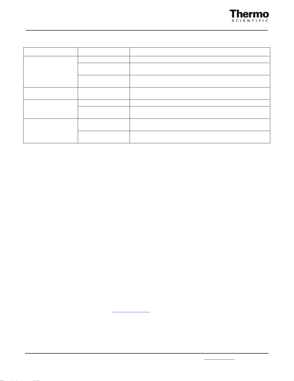
General Troubleshooting and LED Display Errors
Problem Cause Solution
Unit will not operate (no
display lights illuminate
and unit does not heat)
Unit is unplugged Verify that unit is plugged in
Blown or missing fuse Verify that unit has two fuses (same rating) inserted into power entry
module, and that both fuses are functional
Incorrect voltage setting Verify that the voltage setting switch on back of the unit is properly
configured
Unit will not operate
(“888” shows on display)
Software error occurred
and needs to be reset
Cycle power to unit by unplugging power cord for 5 seconds and then
reconnecting
Incorrect voltage setting Verify voltage setting switch on back of the unit is properly set Erratic heat control
All other errors
Excessive and/or erratic
ventilation around unit
Connection error
detected by unit
Protect unit from experiencing continually varying airflow that
interferes with constant heat dissipation and measurement
Cycle power to unit by unplugging power cord for 5 seconds and then
reconnecting
Various Contact manufacturer or other trained service personnel. Use proper
ESD precautions when servicing
Service and Maintenance
Replacement parts and repair services are available for Reacti-Therm Modules. Contact our Technical Support Department.
Related Thermo Scientific Products
18915 Thermometer, range 0-200°C
18820 Remote Temperature Probe
18825 Reacti-Vap Evaporator (9-port)
18826 Reacti-Vap III Evaporator (27-port)
18801-18819 Reacti-Block Aluminum Blocks
13100-13225 Reacti-Vial Small Reaction Vials (12/pkg)
29550 Vacuum Hydrolysis Tubes, 1 ml
29560 Vacuum Hydrolysis Tubes, 5 ml
29564 Vacuum Hydrolysis Tubes, 20 ml
This product (“Product”) is warranted to operate or perform substantially in conformance with published Product specifications in effect at the time of sale,
as set forth in the Product documentation, specifications and/or accompanying package inserts (“Documentation”) and to be free from defects in material and
workmanship. Unless otherwise expressly authorized in writing, Products are supplied for research use only. No claim of suitability for use in applications
regulated by FDA is made. The warranty provided herein is valid only when used by properly trained individuals. Unless otherwise stated in the
Documentation, this warranty is limited to one year from date of shipment when the Product is subjected to normal, proper and intended usage. This
warranty does not extend to anyone other than the original purchaser of the Product (“Buyer”).
No other warranties, express or implied, are granted, including without limitation, implied warranties of merchantability, fitness for any particular
purpose, or non infringement. Buyer’s exclusive remedy for non-conforming Products during the warranty period is limited to replacement of or
refund for the non-conforming Product(s).
There is no obligation to replace Products as the result of (i) accident, disaster or event of force majeure, (ii) misuse, fault or negligence of or by Buyer, (iii)
use of the Products in a manner for which they were not designed, or (iv) improper storage and handling of the Products.
Current versions of product instructions are available at www.thermo.com/pierce
© 2009 Thermo Fisher Scientific Inc. All rights reserved. Unless otherwise indicated, all trademarks are property of Thermo Fisher Scientific Inc. and its
subsidiaries. Printed in the USA.
. For a faxed copy, call 800-874-3723 or contact your local distributor.
Pierce Biotechnology PO Box 117 (815) 968-0747 www.thermo.com/pierce
3747 N. Meridian Road Rockford, lL 61105 USA (815) 968-7316 fax
Artisan Technology Group - Quality Instrumentation ... Guaranteed | (888) 88-SOURCE | www.artisantg.com
5
Page 7

Artisan Technology Group is your source for quality
new and certied-used/pre-owned equipment
• FAST SHIPPING AND
DELIVERY
• TENS OF THOUSANDS OF
IN-STOCK ITEMS
• EQUIPMENT DEMOS
• HUNDREDS OF
MANUFACTURERS
SUPPORTED
• LEASING/MONTHLY
RENTALS
• ITAR CERTIFIED
SECURE ASSET SOLUTIONS
SERVICE CENTER REPAIRS
Experienced engineers and technicians on staff
at our full-service, in-house repair center
Instra
Remotely inspect equipment before purchasing with
our interactive website at www.instraview.com
Contact us: (888) 88-SOURCE | [email protected] | www.artisantg.com
SM
REMOTE INSPECTION
View
WE BUY USED EQUIPMENT
Sell your excess, underutilized, and idle used equipment
We also offer credit for buy-backs and trade-ins
www.artisantg.com/WeBuyEquipment
LOOKING FOR MORE INFORMATION?
Visit us on the web at www.artisantg.com for more
information on price quotations, drivers, technical
specications, manuals, and documentation
 Loading...