

Page 1

50125612-3 dicembre 2010
Thermo Fisher Scientific
RC BIOS
Instruction Manual
Page 2

IMPORTANT!
Please reference this page for the most up-to-date information on the
following*
• web site addresses
• contact information
• copyright and trademark information
*All subsequent pages in this manual may have incorrect web site addresses and contact information.
©2013 Thermo Fisher Scientific Inc. All rights reserved. Delrin, TEFLON, and Viton are registered
trademarks of DuPont. Noryl is a registered trademark of SABIC. POLYCLEAR is a registered
trademark of Hongye CO., Ltd. Hypaque is a registered trademark of Amersham Health As. RULON A
and Tygon are registered trademarks of Saint-Gobain Performance Plastics. Alconox is a registered
trademark of Alconox. Ficoll is a registered trademark of GE Healthcare. Haemo-Sol is a registered
trademark of Haemo-Sol. Triton X-100 is a registered trademark of Sigma-Aldrich Co. LLC. All other
trademarks are the property of Thermo Fisher Scientific Inc. and its subsidiaries.
Manufacturer
Thermo Fisher Scientific
Robert-Bosch-Straße 1
D - 63505 Langenselbold
Germany
Thermo Fisher Scientific Inc. provides this document to its customers with a product purchase to use
in the product operation. This document is copyright protected and any reproduction of the whole or
any part of this document is strictly prohibited, except with the written authorization of Thermo Fisher
Scientific Inc.
The contents of this document are subject to change without notice. All technical information in this
document is for reference purposes only. System configurations and specifications in this document
supersede all previous information received by the purchaser.
Thermo Fisher Scientific Inc. makes no representations that this document is complete,
accurate or error-free and assumes no responsibility and will not be liable for any errors,
omissions, damage or loss that might result from any use of this document, even if the
information in the document is followed properly.
This document is not part of any sales contract between Thermo Fisher Scientific Inc. and a
purchaser. This document shall in no way govern or modify any Terms and Conditions of Sale, which
Terms and Conditions of Sale shall govern all conflicting information between the two documents
Page 3
ThermoFisher
SCIENTIFIC
Ko
N
Fo nru
rrÄrsERKLAnu
ruc
(2006
I 421 EG; 2006/95/EG', 20041 108/EG)
DECLARATION
OF
CONFORMITY
(2006
I 421 EC; 2006/95/EC
;
2oo4 I 1
08
t EC)
DECLARATION DE CONFORMITE
(2006
I 42t CE;
2006/95/C E ; 2004 I
1 08
I
CE)
Produkt: Labor-Zentrifuge
Product: Laboratory
centrifuge
Produit: Centrifugeuse de laboratoire
Gerät:
Modet:
Rc12 BP+
Modöte:
Rc Blos
Best.-Nr.:
75007032,
75007033
Cat.-No.:
75007036
,75007097
Röförence:
Dr. Thomas
Reck
Werkleiter
C€
Dieses Produkt
wurde
in
Übereinstimmung
mit den Richtlinien
2006/95/EG
N iederspan nu ng, 2006 I 42lEG Masch
i nen,
20041 108/EG
elektromagnetische
Verträg
lichkeit
(E
M\,f hergestel lt u nd
geprüft.
This
product
is manufactured
and
duly carried out
in
compliance with
directions
2006/95/EC
Low
Voltage,2006142lEC Machinery, 20041108/EC electromagnetic
compatibility
(EMC).
Ce
produit
est fabriqu6
et
testö
selon
les directives
2006/95/CE mat6riel
6lectrique destin6 ä ötre
employ6
dans certaines limites de tension,
2006 I 42 I CE machi nes, 2OO4 I 1
08/CE
I a com
pati
bil it6
6lectroma
g
n6ti
q
ue.
Normen / Standards /
Normes:
EN 61010-1: 2004
I EN
61010-2-020:2006
EN 61 326-1:2006
I EN
5501
18:2007
/ EN 61000-6-2: 2005
Osterode, den 08.09.201 0
Thermo Electron LED GmbH
Werk Osterode
Am
Kalkberg
D-37520 Osterode
atum Jol(ument Revision
"stelll
l8 09 2010 29707033-0 50124625.doc
00
Freioeoeben Abdullah Laaboubr l8 09.201 0
V \HSNOC\KONF
Page 4

WEEE Conformity
This product is subject to the regulations of the EU Waste Electrical & Electronic Equipment (WEEE)
Directive 2002/96 It is marked by the following symbol:
Thermo Fisher Scientific has entered into agreements with recycling and disposal companies in all EU
Member States for the recycling and disposal of this device. For information on recycling and disposal
companies in Germany and on the products of Thermo Fisher Scientific, which fall under the RoHS
Directive (Restriction of the use of certain hazardous substances in electrical and electronic
equipment), please visit the website www.thermo.com/WEEERoHS
Page 5

Thermo Scientific RC BIOS i
T
Preface .......................................................................................................................................iii
Scope of Supply ........................................................................................................................iii
Intended Use ............................................................................................................................. iv
Accident Prevention ................................................................................................................ iv
Precautions ............................................................................................................................... iv
Chapter 1 Introduction and Description ...............................................................................................1-1
Characteristics of the RC BIOS ................................................................................1-2
Technical Data .........................................................................................................1-3
Directives, Standards and Guidelines ....................................................................................... 1-4
Functions and Features ............................................................................................................. 1-4
Mains Supply ...........................................................................................................1-5
Rotor Selection .........................................................................................................1-5
Chapter 2 Before use ................................................................................................................................2-1
Before Setting up ......................................................................................................2-2
Location ...................................................................................................................2-2
Installation ...............................................................................................................2-2
Aligning the Centrifuge ............................................................................................2-5
Transporting the Centrifuge .....................................................................................2-5
Mains Connection ....................................................................................................2-5
Other connections ....................................................................................................2-6
Storage .....................................................................................................................2-6
Chapter 3 Control Panel ...........................................................................................................................3-1
CONTROLL PANEL ..............................................................................................3-2
KEYS ........................................................................................................................3-2
RUN DISPLAY .......................................................................................................3-3
PRIMARY FUNCTION KEYS ...............................................................................3-4
SET DISPLAY .........................................................................................................3-7
KEYPAD LOCK ......................................................................................................3-8
Chapter 4 Operation .................................................................................................................................4-1
Switch on Centrifuge ................................................................................................4-2
Lid Opening .............................................................................................................4-2
Close Lid ..................................................................................................................4-2
Rotor Installation .....................................................................................................4-3
Normal Operation ....................................................................................................4-3
Centrifugation ..........................................................................................................4-5
Table of Contents
Page 6

Contents
ii RC B
IOS Thermo Scientific
Programmed Operation ........................................................................................... 4-6
Using Advanced Features (Options) ......................................................................... 4-8
Temperature Control ............................................................................................. 4-13
Rotor Temperature Equilibration .......................................................................... 4-14
Chapter 5 Customer Control Inspection ..............................................................................................5-1
Speed Controls ........................................................................................................ 5-2
Timer Controls ........................................................................................................ 5-2
Temperature Controls ............................................................................................. 5-3
Chapter 6 Maintenance and Care .........................................................................................................6-1
Cleaning Intervalls ................................................................................................... 6-2
Cleaning .................................................................................................................. 6-2
Disinfection ............................................................................................................. 6-4
Decontamination ..................................................................................................... 6-5
Autoclaving .............................................................................................................. 6-5
Service of Thermo Fisher Scientific .......................................................................... 6-6
Chapter 7 Troubleshooting ....................................................................................................................7-1
Mechanical Emergency Door Release ...................................................................... 7-2
Circuit Breakers ....................................................................................................... 7-3
Failure message ........................................................................................................ 7-3
Chemical Compatibility Chart ..............................................................................A-1
Warranty ...................................................................................................................B-1
Contact Information ................................................................................................C-1
Page 7

Thermo Scientific RC BIOS iii
P
Preface
Before starting to use the centrifuge, read through this instruction manual carefully and follow the
instructions.
The information contained in this instruction manual is the property of Thermo Fisher Scientific. It is
forbidden to copy or pass on this information without explicit approval.
Failure to follow the instructions and safety information in this instruction manual will result in the
expiration of the sellers warranty.
Scope of Supply
If any parts are missing, please contact your nearest Thermo Fisher Scientific representative.
This symbol refers to general hazards.
CAUTION means that material damage could occur.
WARNING means that injuries or material damage or contamination could occur.
This symbol refers to a rotor failure.
3~
This symbol refers 3 phase alternating current.
Article Number Quantity Check
Centrifuge RC BIOS 1
Power supply cable 1
50105346 Instruction manual 1
70907249 Installation kit 1
Page 8

P
Intended Use
iv RC B
IOS Thermo Scientific
Intended Use
• This centrifuge is a laboratory product designed to separate components by generation of Relative
Centrifugal Force. It separates human samples (e.g. blood, urine and other body fluids) collected in
appropriate containers, either alone or after addition of reagents or other additives.
• The centrifuge is designed to also run other containers filled with chemicals, environmental
samples and other non-human body samples.
• This centrifuge should be operated by trained specialists only.
Accident Prevention
Precautions
In order to ensure safe operation of the centrifuge, the following general safety regulations must be
followed. Ignoring the safety regulations can result in severe damage and inguries.
• Do not manipulate the safety devices
• The centrifuge should be operated by trained specialists only.
• The centrifuge is to be used for its intended purpose only.
• Plug the centrifuge only into sockets which have been properly grounded.
• Do not move the centrifuge while it is running.
• Use only rotors and accessories for this centrifuge which have been approved by Thermo Fisher
Scientific. Exceptions to this rule are commercially available glass or plastic centrifuge tubes,
provided they have been approved for the speed or the RCF value of the rotor.
Prerequisite for the safe operation of the centrifuge is a work environment in compliance
with standards, directives and trade association safety regulations and proper instruction of
the user.
The safety regulations contain the following basic recommendations:
• Maintain a radius of at least 30 cm (12 inch) around the centrifuge.
• Implementation of special measures which ensure that no one can approach the
centrifuge for longer than absolutely necessary while it is running.
The mains plug and main switch must be freely accessible at all times. Pull out the power
supply plug or disconnect the power supply in an emergency.
Page 9

P
Precautions
Thermo Scientific RC B
IOS v
• Do not use rotors which show any signs of corrosion and/or cracks.
• Do not touch the mechanical components of the rotor and do not make any changes to the
mechanical components.
• Use only with rotors which have been properly installed. Follow the instructions in section “Rotor
Installation” on page 4-3.
• Use only with rotors which have been loaded properly. Follow the instructions given in the rotor
manual.
• Never overload the rotor. Follow the instructions given in the rotor manual.
• Never start the centrifuge when the lid is open.
• Never open the lid until the rotor has come to a complete stop and this has been confirmed in the
display.
• The lid emergency release may be used in emergencies only to recover the samples from the
centrifuge, e.g. during a power failure (see section “Failure message” on page 7-3).
• Never use the centrifuge if parts of its cover panels are damaged or missing.
• Do not touch the electronic components of the centrifuge or alter any electronic or mechanical
components.
• Please observe the safety instructions.
Please pay particular attention to the following aspects:
• Location: well-ventilated environment, set-up on a level and rigid surface with adequate
load-bearing capacity.
• Rotor installation: make sure the rotor is locked properly into place before operating the
centrifuge.
• Especially when working with corrosive samples (salt solutions, acids, bases), the accessory parts
and vessel have to be cleaned carefully.
• Always balance the samples.
Centrifuging hazardous substances:
• Do not centrifuge explosive or flammable materials or substances which could react violently with
one another.
• The centrifuge is neither inert nor protected against explosion. Never use the centrifuge in an
explosion-prone environment.
• Do not centrifuge inflammable substances.
• Do not centrifuge toxic or radioactive materials or any pathogenic micro-organisms without
suitable safety precautions.
When centrifuging microbiological samples from the Risk Group II (according to the Bio-safety
Manual" of the World Health Organization WHO), aerosol-tight biological seals have to be used.
For materials in a higher risk group, extra safety measures have to be taken.
Page 10

P
Precautions
vi RC B
IOS Thermo Scientific
• If toxins or pathogenic substances have gotten into the centrifuge or its parts, appropriate
disinfection measures have to be taken (see “Disinfection” on page 6-4).
• Highly corrosive substances which can cause material damage and impair the mechanical stability
of the rotor, should only be centrifuged in corresponding protective tubes.
IF A HAZARDOUS SITUATION OCCURS, TURN OFF THE POWER SUPPLY TO THE
CENTRIFUGE AND LEAVE THE AREA IMMEDIATELY.
Normal use
The centrifuge is to be used for separating materials of different density or particle size suspended in a
liquid.
Maximum sample density at maximum speed: 1,2
g
cm
3
---------- -
Page 11

Thermo Scientific RC BIOS 1-1
1
Introduction and Description
Contents
• “Characteristics of the RC BIOS” on page 1-2
• “Technical Data” on page 1-3
• “Directives, Standards and Guidelines” on page 1-4
• “Functions and Features” on page 1-4
• “Mains Supply” on page 1-5
• “Rotor Selection” on page 1-5
Page 12

1
Introduction and Description
Characteristics of the RC BIOS
1-2 RC B
IOS Thermo Scientific
Characteristics of the RC BIOS
The maintenance-free induction motor ensures quiet and low-vibration operation even at high speeds,
and guarantees a very long lifetime.
The user-friendly control panel makes it easy to pre-set the speed, RCF value, running time,
temperature, and running profile (acceleration and braking curves). You can choose between the
display of speed and RCF or the entry mode.
These settings can be changed even while the centrifuge is running.
The RC BIOS is equipped with various safety features:
Housing, rotor chamber, baseframe, and guard ring are made of high-strength, high-quality steel.
• The lid is equipped with a view port and a lock.
• The lid of the centrifuge can only be opened while the centrifuge is switched on and the rotor has
come to a complete stop. The centrifuge cannot be started until the lid has been closed properly.
• Electronic imbalance detection.
• Lid emergency release: For emergencies only, e.g. during power failures (see “Failure message” on
page 6-3)
Page 13

1
Introduction and Description
Technical Data
Thermo Scientific RC B
IOS 1-3
Technical Data
The technical data of the RC BIOS is listed in the following table.
Table 1-1. Technical Data RC B
IOS
Feature Value
Environmental conditions -Use in interior spaces
-Altitudes of up to 2,000 m above sea level
-max. relative humidity 80% up to 31 °C; decreasing linearly up to 50%
relative humidity at 40 °C
permissible ambient temperature +2° C to +40° C +35.6° F to +104° F
Overvoltage category II II II
Pollution degree 2 2 2
Heat dissipation 230V 208V 400V
~5.2 kW ~4.5 kW ~5.8 kW
17700 BTU/h 15300 BTU/h 19700 BTU/h
IP 20 20 20
Running time unlimited unlimited unlimited
Maximum speed n
max
8500 rpm 8500 rpm 8500 rpm
Minimum speed n
min
300 rpm 300 rpm 300 rpm
Minimum sample temperature 4°C at 8500 rpm 4°C at 7800 rpm 4°C at 8500 rpm
Maximum RCF value at n
max
15860 x g 15860 x g 15860 x g
Maximum kinetic energy <212 kJ < 212 kJ < 212 kJ
Noise level at maximum speed
a
< 65 dB (A) < 65 dB (A) < 65 dB (A)
Temperature setting range -10 °C to +40 °C -10 °C to +40 °C -10 °C to +40 °C
Dimensions
Height
Width
Depth
Length power cord
1178 mm
800 mm
905 mm
3000 mm
46.3 inch
31.5 inch
35.6 inch
118.1 inch
Weight without rotor 475 kg 1047 lb
a
front side measurement
Page 14

1
Introduction and Description
Directives, Standards and Guidelines
1-4 RC B
IOS Thermo Scientific
Directives, Standards and Guidelines
Functions and Features
The following table gives an overview of the important functional and performance characteristics of
the RC BIOS.
Table 1-2. Directives, standards and guidelines
Tension /
Frequency
Produced and inspected according to the following
standards and guidelines
220V-230V 50Hz,
400V 50Hz
2006/95/EC Low Voltage Directive:
2006/42/EC Machine Directive:
2004/108/EC EMC Directive
EN 61010-1, 2
nd
Edition
EN 61010-2-020, 2
nd
Edition
EN 61326-1
EN 55011B
EN 61000-6-2
208-220V 60Hz,
230V 60Hz
The centrifuges are produced and inspected
according to the following standards and
guidelines
UL 61010-1, 2
nd
Edition
CAN/CSA-C22.2 No. 61010-1, 2
nd
Edition
IEC 61010-2-20, 2
nd
Edition
(Pollution degree 2, Overvoltage category II)
Emitted interference FCC Part 15 A
NOTE: This equipment has been tested and found to comply with
the limits for a Class A digital device, pursuant to Part 15 of the
FCC Rules. These limits are designed to provide reasonable
protection against harmful interference when the equipment is
operated in a commercial environment. This equipment
generates, uses, and can radiate radio frequency energy and, if
not installed and used in accordance with the instruction manual,
may cause harmful interference to radio communications.
Operation of this equipment in a residential area is likely to
cause harmful interference in which case the user will be
required to correct the interference at his own expense.
Table 1-3. Functions and features
Component / Function Description / Features
Structure / Housing Galvanized and powder doated high-strength steel chassis and guard-ring
Chamber Stainless steel
Drive Induction drive without carbon brushes
Keys and display Easy-to-clean keypad and display surface
Controls Microprocessor-controlled
Internal memory The most recent data is saved
Functions RCF-selection, temperature control
Acceleration / braking profiles 11 acceleration and 11 braking curves
Imbalance detection Electronic, contingent on rotor and speed
Lid lock Automatic lid closing and locking starting from an initial hold position
Page 15

1
Introduction and Description
Mains Supply
Thermo Scientific RC B
IOS 1-5
Mains Supply
The following table contains an overview of the electrical connection data for the RC BIOS. This data is
to be taken into consideration when selecting the mains connection socket.
Rotor Selection
RC BIOS is sold commercially in a package solution (unit and rotor included).
The rotor that is available for use in the RC B
IOS:
The technical data of the rotors and the corresponding adapters and reduction sleeves for various
commercially available containers can be found in the corresponding rotor operating manuals.
For more information visit our website at: http://www.thermo.com
Table 1-4. Electrical connection data of the RC BIOS
Cat. Mains voltage Frequency
Rated current
Power consumption
Equipment
fuse
Building
fuse
Supply Power
Plugs
75007034 208-220V 60Hz 23.5 A 4400W 25A & 6A 30 A NEMA 6-30P
SinglePhase
75007035 230V 60Hz 22.5 A 4500 W 25A & 6A 30 A NEMA 6-30P
SinglePhase
75007036 220V-230V 50Hz 22 A 4300 W 25A & 6A 32A IEC60309 CEE 32
A-6h 1P+N+PE
75007037 230V/ 400V 3 50Hz 20.5 A 3800 W 25A & 6A 3x 32A IEC60309 CEE 32
A-6h 3P+N+PE
F8-6x1000y 096-061137
Page 16

Thermo Scientific RC BIOS 2-1
2
Before use
Contents
• “Before Setting up” on page 2-2
• “Location” on page 2-2
• “Installation” on page 2-2
• “Aligning the Centrifuge” on page 2-5
• “Transporting the Centrifuge” on page 2-5
• “Mains Connection” on page 2-5
• “Other connections” on page 2-6
• “Storage” on page 2-6
Page 17
2
Before use
Before Setting up
2-2 RC B
IOS Thermo Scientific
Before Setting up
1. Check the centrifuge and the packaging for any shipping damage.
Inform the shipping company and Thermo Fisher Scientific immediately if any damage is
discovered.
2. Remove the packaging.
3. Check the order for completeness (see “Scope of Supply” on page iii).
If the order is incomplete, please contact Thermo Fisher Scientific.
Location
The centrifuge should only be operated indoors.
The set-up location must fulfil the following requirements:
• A safety zone of at least 30 cm must be maintained around the centrifuge.
People and hazardous substances must be kept out of the safety zone while centrifuging.
• The supporting structure must be stable and free of resonance.
• The supporting structure must be suitable for horizontal setup of the centrifuge.
• The centrifuge should not be exposed to heat and strong sunlight.
• The set-up location must be well-ventilated at all times.
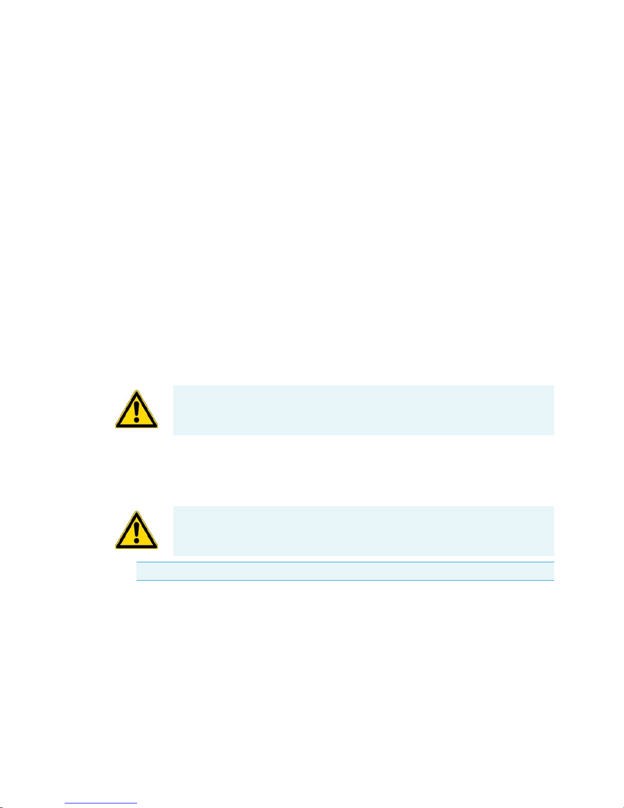
Installation
1. Place the pallet with the centrifuge so that you have at leased 2 m room in front of the pallet.
2. Release the rails from the pallet.
3. Screw the rails onto the pallet in front of the centrifuge.
WARNING UV rays reduce the stability of plastics.
Do not subject the centrifuge, rotors and plastic accessories to direct sunlight.
WARNING The centrifuge operates with high kinetic energies. Do not run the centrifuge
without a radius of at least 30 cm (12 inch) around the centrifuge.
Do not run the centrifuge while standing on its casters.
Note The centrifuge is screwed onto the pallet with four screws.
Page 18
2
Before use
Installation
Thermo Scientific RC B
IOS 2-3
4. Place the piece of wood under the rails.
5. Place the rubber feet under the studs with the safety brackets and screw them entirely up.
6. Remove the four screws that fix the centrifuge t the pallet. The heads are upsiede down in the
pallet.
7. Remove the bolt spacers.
8. Screw the studs with the safety brackets entirely up. Otherwise they might get stuck when rolling
the centrifuge off the pallet.
9. Remove the rubber feet.
Rails
Safety brackets
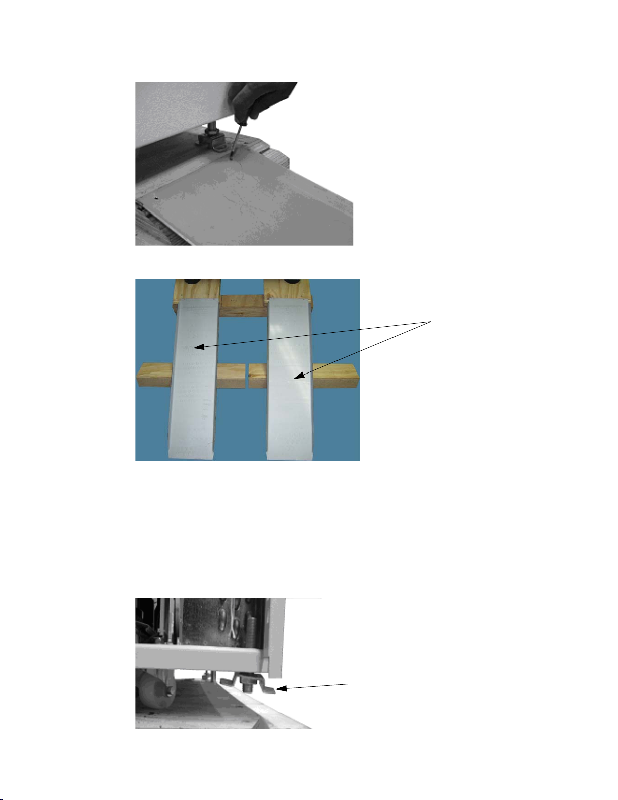
Page 19
2
Before use
Installation
2-4 RC B
IOS Thermo Scientific
10. Check that the stearing casters point to the back.
11. Use several people and other means in order to roll the centrifuge off the pallet.
12. Once the centrifuge is in its final position mount the enclosed locking stabilizers.
13. Screw the studs down.
14. Place the rubber feet centrally and align the centrifuge. All the rubber feet should carry uniformly
(check by a tilt test). The casters are at a distance of about 5-15 mm from the ground.
15. Switch on the centrifuge.
16. Open the centrifuge.
17. Put the enclosed water level on the drive spindle.
18. Use a wrench to rotate the safety brackets alternately to raise or lower them until the centrifuge is
leveled.
19. Remove the water level when the centrifuge is leveled.
20. Be sure that the four locking stabilizers stand safe and don't jolt. The final assembly of the safety
brackets is carried out after leveling.
21. Tighten the locking nuts of the locking stabilizers firmly.
Mount the safety brackets by means of an 8 mm open-end wrench on the stabilizers.
22. Optional: To be certain the centrifuge is working properly, refer to the Customer Control
Inspection paragraph located in “Customer Control Inspection” on page 5-1. Perform the
procedures listed under Speed Control, Timer, and Temperature Control.
WARNING Due to the centrifuges weight it must be controlled by several people and
other means when rolling of the pallet. Do not stand in front of the centrifuge when
rolling down for the centrifuge might run you over.
CAUTION If the centrifuge isn’t level, imbalances can occur and the centrifuge can be
damaged.
Do not place anything under the feet to level the centrifuge.
Page 20
2
Before use
Aligning the Centrifuge
Thermo Scientific RC B
IOS 2-5
Aligning the Centrifuge
The horizontal alignment of the centrifuge must be checked every time after moving it to a different
location.
The supporting structure must be suitable for horizontal setup of the centrifuge.
Transporting the Centrifuge
• Use a forklift to lift the centrifuge.
• The centrifuge can be damaged by impacts.
• Transport the centrifuge upright and if at all possible in packaging.
Mains Connection
1. Turn off the power supply switch located on a small recessed panel in the upper right corner of the front
cabinet panel (press "0").
2. Plug the centrifuge into grounded electrical sockets only.
3. Check whether the cable complies with the safety standards of your country.
4. Make sure that the voltage and frequency correspond to the figures on the rating plate.
5. Establish the connection to the power supply with the connecting cable.
Note The packaging is an one-way packaging. Assign a logistic company for the transport. Contact
Customer Service.
WARNING Always remove the rotor before moving the centrifuge.
Page 21
2
Before use
Other connections
2-6 RC B
IOS Thermo Scientific
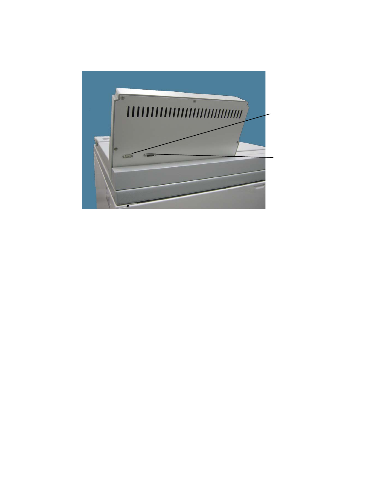
Other connections
Figure 2-1. Connetors to external devises
Storage
• Before storing the centrifuge and the accesories it must be cleanedand if necessary desinfected and
decontaminated.
• Store the centrifuge in a clean, dust-free location.
• Be sure to place the centrifuge on its feet.
• Avoid direct sunlight.
15 Pol D-Sub Computer
Interface Connector
9 Pol D-Sub Connector Barcode
Reader
Page 22

Thermo Scientific RC BIOS 3-1
3
Control Panel
Contents
• “KEYS” on page 3-2
• “CONTROLL PANEL” on page 3-2
• “RUN DISPLAY” on page 3-3
• “PRIMARY FUNCTION KEYS” on page 3-4
• “SET DISPLAY” on page 3-7
• “KEYPAD LOCK” on page 3-8
Page 23

3
Control Panel
CONTROLL PANEL
3-2 RC B
IOS Thermo Scientific
CONTROLL PANEL
The controll panel consists of the RUN DISPLAY, the SET DISPLAY, the MENU key with the
OPTION INDICATORS, the PRIMARY FUNCTION KEYS, a NUMMERIC KEY PAD, and a
KEYPAD LOCK.
KEYS
Press the START key to start a run.
Press the STOP key to stop a run.
Press the OPEN key to open the door. The key can only be used under the following conditions: The
centrifuge is switched on. The rotor is not spinning. The is now error message in the display. The
message OPEN appears in the RUN DISPLAY.
Press the ENTER key to confirm a selection. Or to step though the menu.
Use the nummeric keypad to enter values into the SET DISPLAY. CLEAR removes input values or
messages from the SET DISPLAY. */- toggles between positive and negative temperature values.
Press the ROTOR key to enter the rotor selection.
Press the SPEED key to enter the speed or RCF selection.
Press HOLD key to select an continues run.
Press TIME key to enter the time selection.
Press ACE key to enter ACE value.
Press TEMP key to enter the temperature.
KEYPAD LOCK
MENU KEY
PRIMARY FUNCTION KEYS
NUMERIC KEYPAD
SET DISPLAY
RUN DISPLAY
OPTION INDICATORS
Page 24

3
Control Panel
RUN DISPLAY
Thermo Scientific RC B
IOS 3-3
Press RECALL to view and select programmed parameters.
Press MENU to enter advanced features.
RUN DISPLAY
The RUN DISPLAY shows the actual values during a run.
SPEED field
The SPEED (RPM/RCF) field indicates either:
• the current measured rotor speed (in rpm) or,
• the relative centrifugal force (or g-force) that is currently being generated at the maximum radius of
the selected rotor if RCF is selected (RCF indicator is lit).
• At run completion (zero speed) the display shows the word "End" until the door is opened.
TEMPERATURE field
The run TEMPERATURE (°C) field indicates the current calculated sample temperature in degrees
Celsius, based on:
• rotor selected,
• rotor speed,
• run time,
• set temperature, and
• measured temperature.
The calculation assumes that the sample temperature, rotor temperature, and SET temperature are all
equal at the start of the run.
TIME field
The run time can be defined as follows:
You can select TIME/HOLD/ACE mode for a time controlled run.
• If controlled by TIME, the display counts down from set time, showing the time remaining (in
minutes and seconds) until the run terminates and deceleration begins.
• If controlled by HOLD (indicated in the smaller SET DISPLAY below), the display during a run
counts up. The RUN DISPLAY shows the time elapsed (expressed in minutes and seconds, up to a
maximum of 99:59) since START was pressed.
• If controlled by ACE (Accumulated Centrifugal Effect™, ACE indicator lit), the RUN display
shows the current Calculated ACE value ( ). When the set ACE value is reached, the run
terminates and decelerates to a stop. The displayed value continues to calculate the centrifugal
effect during deceleration to zero to show total accumulation.
ω2dt
∫
Page 25

3
Control Panel
PRIMARY FUNCTION KEYS
3-4 RC B
IOS Thermo Scientific
PRIMARY FUNCTION KEYS
The Primary Function keys are the keys below the SET DISPLAY.
ROTOR allows selection of rotors to be used.
SPEED allows changing desired speed (rpm) or RCF (g-force).
TEMP allows changing desired calculated sample temperature.
RECALL allows viewing and selecting programmed parameters.
Each key is positioned below a corresponding field in the SET DISPLAY, allowing simple, direct access
to basic run parameter controls:
ROTOR
• Press the ROTOR key to specify a different rotor than the one shown in the SET DISPLAY. This
is necessary if the rotor or bucket/ carrier system installed in the centrifuge are changed.
• The rotors are listed by the rotor name. Press the ROTOR key repeatabely to scroll through the
rotor list for selection.
• The correct identification of the installed rotor is necessary for the set SPEED limits, correctly
calculate RCF, and accurately control sample temperature.
• If a rotor is able to use buckets/carriers with different maximum radii, each configuration will be
listed for selection, to calculate the different RCF.
• The ROTOR key is not active when a run is in progress.
SPEED
• Press the SPEED key to specify a different rotor speed in revolutions per minute (rpm) or relative
centrifugal force (RCF, also known as g-force).
• Speed is selectable from 300 to 4700 rpm, up to the maximum rated speed for the specified rotor,
or as an equivalent RCF calculated at the maximum radius of the specified rotor (rotor geometry
only, with no accounting for adapters).
• Press the SPEED key repeatedly to toggle between rpm and RCF or RCF. Pressing once causes the
value to flash so a change can be made in that mode. Pressing again changes to the other mode and
displays a value equivalent to the previouse. Pressing again causes that value to flash so a change can
be made, pressing again changes the mode back, and so on.
• An entered value will continue to flash (prompting input) when it is out of range for the SET
rotor. The formula used to calculate RCF is:
Note To ensure that the installed rotor will always be correctly identified, make it a practice to
change the SET rotor name immediately after changing the installed rotor.
RCF 11.18 radius in cm×
rpm
1000
----------- -
⎝⎠
⎛⎞
2
×=
Page 26

3
Control Panel
PRIMARY FUNCTION KEYS
Thermo Scientific RC B
IOS 3-5
The run duration (from start to termination, when deceleration begins) setting or control method is
changed by pressing one of these three PRIMARY FUNCTION KEYS:
TIME
• Press the TIME key to specify a length of time (minutes and seconds, to a maximum of 99:59)
from run start to termination.
• In the RUN DISPLAY, minutes and seconds begin counting down from the input value when
START is pressed.
• The run terminates and deceleration begins when the timer reaches zero.
HOLD
• Press the HOLD key to specify a continuous run which, once started, runs until STOP is pressed
(terminating the run and initiating deceleration).
• During a continuous run, HOLD will be in the SET DISPLAY, and the time elapsed from when
START was pressed will appear in the RUN display.
• The timer will accumulate up to 99 minutes 59 seconds - if a run continues beyond that, the
displayed run time will remain fixed at 99:59. Whenever it is possible for such an extended run to
occur, an external timing method is recommended.
ACE
• Press the ACE key to specify an Accumulated Centrifugal Effect™ value.
• When ACE control is selected, the centrifuge calculates the effect of speed in relation to time (the
shaded area in the illustration below), adjusting run duration to account for acceleration variation.
This variation can be attributed to rotor load/configuration differences (affecting inertia),
fluctuations in line voltage (affecting motor power), or slight mechanical differences including
normal wear.
Note When changing mode, rpm/RCF values may appear a digit or two off from the original set
value. The centrifuge translates set RCF values to rpm whole numbers for speed control purposes,
then calculates that rpm whole number to the closest RCF value. There is no cause for concern.
Speed control accuracy is not compromised, and the slight value difference will not affect your run
TIME
SPEED
Termination Set Point
Page 27

3
Control Panel
PRIMARY FUNCTION KEYS
3-6 RC B
IOS Thermo Scientific
• When START is pressed, the realized ACE value begins to accumulate in the RUN DISPLAY.
• The run will terminate and deceleration will begin when the specified ACE value (expressed as
1
value up to 9.99 x 1030 [displayed as 9.99e30]) is reached.
• After termination, the RUN DISPLAY will continue to accumulate until the rotor stops - this run
total is for reference. Care should be taken not to confuse the RUN DISPLAY's final accumulation
with the controlling input/ timeout value, found in the SET DISPLAY.
• Compared to control by time, ACE selection provides a more advanced and relevant form of run
duration control, thereby improving separation consistency, run reproducibility, and dependability
of results.
• During a run, to view in an alternative duration control mode (for example, to monitor
accumulating TIME when an ACE run is in progress), press one of the other two duration control
keys once - this changes the RUN DISPLAY to show an accumulating value in that alternative
mode without altering the way duration is controlled. In this viewing condition, the SET
DISPLAY field header does not change, nor will the status of the ACE indicator (both continuing
to indicate the set control mode), but the SET value will change to show the last value entered in
the alternative mode. If you press the same key a second time, the run will then change to that
control method, using the value that was in the SET DISPLAY as the controlling value until a
different one is entered.
• Between runs, the RUN DISPLAY shows the previous run duration values. You can choose each
control mode.
• Press the TIME key to see the MIN:SEC value at termination (the SET DISPLAY shows the last
TIME input value).
• Press the HOLD key to see the total MIN:SEC value after deceleration to zero.
• Press the ACE key to see the total ACE of an ACE controlled run. value after deceleration to zero
(the termination value is in the SET DISPLAY). If the previous run was not controlled by ACE,
pressing ACE shows the ACE value at termination (the SET DISPLAY shows the last ACE input
value).
• Always be sure of the control method and value before pressing START.
1
The integral value can be calculated deriving the following formula:
Where
and
Note If you change the duration control mode to TIME during a run, time begin to will count
down from the set value the moment the change is made (unless the run was previously controlled
by time, in which case the run will resume counting down from the value that existed when the
TIME mode was exited). If you change mode to ACE control, the set value that exists at the
moment the change is made will control run termination. If you change to ACE after the run has
exceeded the set value, the run will terminate immediately.
ω2dt
ω2dt∫ω2dt∫ω
2
Δt==
Δt Change in time (seconds)=
ω
2
Angular speed=
2= π n/60 ][
n Speed (rpm)=
Page 28

3
Control Panel
SET DISPLAY
Thermo Scientific RC B
IOS 3-7
TEMP
Press the TEMP key to change the desired calculated sample temperature ( °C) that is controlled by the
centrifuge during a run.
The centrifuge automatically considers the rotor selected, rotor speed, run time, set temperature, and
measured temperature to calculate and maintain sample temperature during the run. The calculation
assumes that the sample temperature, rotor assembly temperature, and SET temperature are all equal at
the start of the run (as they must be any time that temperature control is critical).
RECALL
• Press the RECALL key to access program memory.
• Saved parameters are recalled by inputting a specific program number. Press the START key to
begin a run using the run parameters displayed.
• Programs can easily be recalled and modified to create new run parameters without fear of
damaging the original program, because information that is saved in memory cannot be
overwritten by using the RECALL key (modifying or replacing a program is reserved for the
SELECT SAVE RUN option under the MENU key).
MENU and OPTION INDICATORS
• The MENU key accesses advanced feature options listed below it, plus other features such as saving
parameters to memory.
• Pressing the MENU key to enter the advanced features. After that pressing 1 accesses a secondary
screen to view or enter values, plus confirm option selection. Pressing 0 deselects options. Pressing
ENTER steps through options without changing selections or settings, and on secondary screens,
enters values to select the option. Pressing MENU again exits the options and returns to the SET
DISPLAY without entering/selecting a flashing value.
SET DISPLAY
The SET DISPLAY is used to:
• input and display basic run parameters,
• to select options or other advanced features, and
• to display advisory messages.
• The SET DISPLAY displays currently selected values for the basic run parameters: ROTOR,
SPEED/RCF, TIMED/HOLD/ACE, DEG C and, if displaying a recalled program, PROG #.
• The set values appear in the SET DISPLAY after the centrifuge power has been set ON and the
diagnostic test has been completed.
• If you have pressed MENU to access the options screens, pressing MENU again will return the set
values to the SET DISPLAY.
• The SET DISPLAY is the primary interactive screen on the control panel, and has a role in all
aspects of centrifuge use.
Page 29

3
Control Panel
KEYPAD LOCK
3-8 RC B
IOS Thermo Scientific
KEYPAD LOCK
• The KEYPAD LOCK can be used to limit control panel function.
• It uses a 3-position keyswitch with a key that is removable in any of the 3 positions. Functionality
is as follows:
• The upper position, FULL (full function), allows use of all keys and features, without
restriction.
• The lower position, SINGLE (Run Single Program), minimizes functionality so that set
parameters cannot be changed (START, STOP, and CLEAR are the only active keys).
• The middle position, ANY (Run Any Program), makes it so that users may only perform runs
using run parameters recalled from program memory (only RECALL, the numeric keypad
including ENTER and CLEAR, START and STOP are active).
• Use of the KEYPAD LOCK may offer a considerable advantage, improving process control by
reducing the possibility for operator error, as well as restricting unauthorized run parameter or
program memory changes.
Page 30

Thermo Scientific RC BIOS 4-1
4
Operation
Contents
• “Switch on Centrifuge” on page 4-2
• “Lid Opening” on page 4-2
• “Close Lid” on page 4-2
• “Rotor Installation” on page 4-3
• “Normal Operation” on page 4-3
• “Centrifugation” on page 4-5
• “Programmed Operation” on page 4-6
• “Using Advanced Features (Options)” on page 4-8
• “Temperature Control” on page 4-13
• “Rotor Temperature Equilibration” on page 4-14
Page 31

4
Operation
Switch on Centrifuge
4-2 RC B
IOS Thermo Scientific
Switch on Centrifuge
1. Turn on the power switch located on a small recessed panel in the upper right corner of the front
cabinet panel into position “1“.
The device performs a self-check of its software.
2. Watch the control panel LEDs to be sure that all segments light.
During start-up the SET DISPLAY shows:
• If an error is detected, an error message will appear in the SET DISPLAY.
• If no error is found, the SET DISPLAY will display the values that was displayed when the
centrifuge was turned OFF.
• All OPTIONS selections will also be the same as when the centrifuge was turned OFF.
Lid Opening
1. Press the "OPEN" key .
Close Lid
Close the lid by pressing down on it lightly in the middle or on both sides of it. Two locks close the lid
completely. The lid will close automatically.
Note Make sure the centrifuge is properly installed before turning it ON for the first time, (see
Chapter 2, Installation).
Note If any LED segments do not light, note which ones and inform Customer Service. Continued
operation when the centrifuge is unable to display all run information correctly could mislead an
unaware observer.
WARNING Do not reach into the crack between the lid and the housing. The lid is
drawn shut automatically.
Use the emergency release only for malfunctions and power failures (see “Failure message”
on page 7-3).
WARNING Do not reach into the crack between the lid and the housing. The lid is
drawn shut automatically.
Note The lid should audibly click into place.
Page 32

4
Operation
Rotor Installation
Thermo Scientific RC B
IOS 4-3
Door Gas Springs
Periodically check that the two door gas springs are functioning properly.
a. Open the chamber door and making sure it remains open.
The gas springs counterbalance the weight of the door and hold it in the open position.
If the chamber door will not stay in the open position, inform Customer Service.
b. Check that the gas spring bracket is not cracked.
If the gas spring bracket is cracked, inform Customer Service.
Rotor Installation
The approved rotors for the centrifuge are listed in section “Rotor Selection” on page 1-5. Use only the
rotors and accessories from this list in the centrifuge.
Proceed as follows:
1. Open the lid of the centrifuge and if necessary remove any dust, foreign objects or residue from the
chamber.
2. Follow the instructions given in the rotor manual in order to install, load, and balance the rotor.
3. Close the centrifuge lid.
4. Make sure the rotor matches the rotor in the SET DISPLAY.
5. Press the ROTOR key repeatedly until the name of the installed rotor appears.
Normal Operation
Preselecting Speed / RCF
1. Press the SPEED key.
The display shows the RPM or the RCF-value depending on the display setting. Press the SPEED
key to toggle between the two modes.
2. Enter the desired value using the numeric pad.
The digits show in sequential order.
CAUTION The door gas springs must be checked periodically for proper functioning. If gas
pressure is not sufficient the door will not stay open and possible injury could result.
CAUTION Unapproved or incorrectly combined accessories can cause serious damage to
the centrifuge.
Note If you select a value that is to high for the defined rotor it will not be accepted. The value will
continue to blink.
Page 33

4
Operation
Normal Operation
4-4 RC B
IOS Thermo Scientific
3. Confirm your entry by pressing ENTER.
Your entry will also be automatically confirmed if you do not press any key for 5 seconds.
Preselecting Run time
1. Press the TIME key in order to open the runtime selection menu.
2. Enter the desired runtime using the numeric pad.
The maximum selectable run time is 99:59.
The digits show in sequential order.
3. Confirm your entry by pressing ENTER.
Your entry will be automatically confirmed if you do not press any key for 5 seconds.
ACE
1. Press the ACE key in order to open the ACE selection menu.
2. Enter the desired runtime using the numeric pad.
The maximum selectable ACE is 9.99 x 10
30
(read 9.99e30 in SET DISPLAY)
The digits show in sequential order.
3. Confirm your entry by pressing ENTER.
Your entry will be automatically confirmed if you do not press any key for 5 seconds.
HOLD
Press the HOLD key in order to select the HOLD run. During HOLD, the centrifuge will continue
running until you stop it manually with the STOP key.
Note The equivelant value will be calculated and displayed. If an extremely low RCF value has
been selected, it will be corrected automatically if the resulting speed is less than 300 rpm. This is
because 300 rpm is the lowest selectable speed.
Explanation of RCF Value
The relative centrifugal force is given as a multiple of the force of gravity g. It is a unitless numerical
value which is used to compare the separation or sedimentation capacity of various devices, since it
is independent of the type of device. Only the centrifuging radius and the speed come into play in
it:
r = centrifuging radius in cm
n = Rotational speed in rpm
The maximum RCF value is related to the maximum radius of the tube opening.
Remember that this value is reduced depending on the tubes and adapters used.
This can be accounted for in the calculation above if required.
RCF 11 18,
n
1000
-------------
〈〉
2
r××=
Page 34

4
Operation
Centrifugation
Thermo Scientific RC B
IOS 4-5
Preselecting temperature
You can preselect temperatures between -10 °C and +40 °C.
1. Press the TEMP key in order to enter the temperature.
2. Enter the desired temperature using the numeric pad.
The digits show in sequential order.
3. Confirm your entry by pressing ENTER.
Your entry will be automatically confirmed if you do not press any key for 5 seconds.
Centrifugation
Once the rotor has been properly installed, the main switch has been turned on and the door has been
closed, you can start centrifugation
Starting centrifuge program
1. Press the START key on the control panel.
The centrifuge accelerates to the pre-set speed with the time display active.
2. You cannot open the door while the centrifuge is running.
Imbalance indicator
If a load is imbalanced, this will be indicated by the message "ROTOR IMBALANCE - BALANCE
ROTOR".
The run will terminate.
Check the loading and start the centrifuge once again. See the information on proper loading in the
rotor instruction manual. For information on troubleshooting, see section “Troubleshooting by user”
on page 7-3.
Stopping the centrifugation program
Set run time
Usually the run time is preset and you only have to wait until the centrifuge stops automatically when
the preset time limit expires.
As soon as the speed drops to zero, the message "END" will appear in the SPEED field. By pressing the
OPEN key, you can open the lid and remove the centrifuge material.
You can also stop the centrifugation program manually at any time by pressing the STOP key.
ACE
When you select an ACE controll run, the run will determine when the centrifuge has reached the set
ACE value.
Page 35

4
Operation
Programmed Operation
4-6 RC B
IOS Thermo Scientific
HOLD
If you selected continuous operation (see “HOLD” on page 4-4), you will have to stop the centrifuge
manually. Press the STOP key on the control panel. The centrifuge will be decelerated at the
designated rate. The message "END" will illuminate, and after pressing the key OPEN, the lid will
open and you can remove the samples.
Programmed Operation
Storing Selections to Program Memory
1. Establish all desired run parameters as explained above, “Normal Operation” on page 4-3.
To minimize the time it takes to perform a QC RUN, we recommend the following:
• Starting with program 1, save runs to program memory: first by temperature (highest first), then,
by speed (lowest first).
FOR EXAMPLE: The programs below are listed in correct order for using QC RUN function
(program values shown are for example purposes only, actual set parameters will vary).
2. Press the MENU key to access the advanced features screens.
3. Press the ENTER key (six times after first accessing the advanced features) until the following
screen is in the SET DISPLAY:
4. Press 1.
The following screen will appear in the SET DISPLAY:
Note If you plan on using the QC RUN feature, consider the following as you save runs to
program memory:
• QC programs should all apply to using the same rotor.
• QC RUN programs should not use HOLD.
ROTOR SPEED TIMED DEG C PROG #
F8-6x1000y 2900 04:00 22 1
F8-6x1000y 4000 03:00 22 2
F8-6x1000y 3800 03:45 4 3
F8-6x1000y 4700 05:30 4 4
Note Single-digit program numbers 1-9 are for storing sets of standard run parameters.
Double-digit program numbers 10-15 are for storing step-runs.
Page 36

4
Operation
Programmed Operation
Thermo Scientific RC B
IOS 4-7
5. Enter a program number.
6. Press ENTER key.
The SET DISPLAY will then return to the HOME screen, and that program number will appear
in the PROG # field as confirmation:
7. Record saved information on the Program Log Pad (supplied).
To review stored programs before overwriting, refer to your Program Log Pad or press RECALL. If you
press RECALL, you will have to go back and re-establish the run parameters before you can store them
to memory.
Performing a Programmed Run
Read the Safety Information Page at the front of this manual.
1. Press RECALL .
The SET DISPLAY will change to display a program number flashing in the PROG # field.
2. Input the desired program number, then press ENTER key.
The SET DISPLAY and options indicators change to reflect the run parameters that were saved to
that program number.
3. Prepare the rotor according to the rotor manual.
4. Open the chamber door and install the rotor, making sure that the rotor is fully seated and locked
to the drive spindle. Install the rotor cover, if any, then close the chamber door.
5. If using logging software, make sure it is running, then press START key.
The rotor will accelerate according to the recalled parameters, and continue until run termination. At
termination, the rotor will decelerate to a stop. After it stops "End" will appear in the SPEED display
and remains there until the door is opened or the START key will be pressed.
Note To prevent accidental erasure of established programs, if the entered program number has
been previously assigned, the following message will appear:
Note Rotor names are saved within the program. If the rotor is changed by selecting a different
program this will be indicated in the SET DISPLAY. Be sure that the installed rotor is correct for
the recalled program. Make sure that the SET rotor identifies the installed rotor.
Note If you select a program number that has not been used to save a program, a warning message
will be displayed. In this case no program will be recalled.
Page 37

4
Operation
Using Advanced Features (Options)
4-8 RC B
IOS Thermo Scientific
Using Advanced Features (Options)
The advanced features of the centrifuge allow for:
• performing quality control runs, changing speed or time control ranges,
• changing acceleration/deceleration or overtemperature alert settings,
• linking together programmed run parameters, and
• saving run parameters to program memory for simple recall.
Advanced feature selection is usually reflected by LED option status indicators. When a feature has
been selected, the corresponding indicator will be lit (although specific settings for several features
can only be checked by reselecting the feature in the options screens). If changes to advanced feature
selection are required (other than to RPM/RCF or TIME/HOLD/ACE status, which are accessible
through primary function keys). The features are accessed by pressing MENU and then pressing
ENTER until the selection screen of the particular feature appears in the SET DISPLAY.
• The MENU key accesses advanced feature options listed below it, plus other features such as
saving parameters to memory.
Press the MENU key to enter the advanced features. After that pressing 1 accesses a secondary screen
to view or enter values, plus confirm option selection. Pressing 0 deselects options. Pressing ENTER
steps through options without changing selections or settings, and on secondary screens, enters
values to select the option. Pressing MENU exits the options and returns to the SET DISPLAY
without entering/selecting a flashing value.
Page 38

4
Operation
Using Advanced Features (Options)
Thermo Scientific RC B
IOS 4-9
Figure 4-1. Advanced Feature Option Screens
1
MENU
MENU
0 or ENTER
ENTER
START
ENTER
ENTER
ENTER
ENTER
ENTER
1
1
1
1
1
1
MENU
MENU
MENU
MENU
MENU
MENU
0 or ENTER
0 or ENTER
0 or ENTER
0 or ENTER
0 or ENTER
0 or ENTER
HOME SCREEN
Page 39

4
Operation
Using Advanced Features (Options)
4-10 RC B
IOS Thermo Scientific
SELECT QC RUN
• QC RUN allows simple, automatic quality control run speed/ temperature verification when used
with the optional computer interface package. The QC RUN feature will run and document the
data from each set of parameters that has been saved in program memory.
• When QC RUN is selected, the SET DISPLAY will prompt you to prepare for the run and press
the START key to begin. The centrifuge will start running program number 1, and systematically
run each program in-order through program number 9.
• While the QC RUN is in progress, the parameters of the program that is running will be in the
SET DISPLAY.
• During a QC RUN the centrifuge checks if the preset speed and temperature can be reached. In
order to save time during the QC RUN the next program will be run once the desired speed has
been reached and the temperature is within °K of the preset value.
• To minimize the time it takes to perform a QC RUN, we recommend the following: Starting with
program 1, save runs to program memory. Sort first by temperature (highest first), then, if there is
more than one run at a single temperature, by speed (lowest first).
FOR EXAMPLE: The programs below are listed in correct order for using QC RUN (program
values shown are for example purposes only, actual set parameters will vary).
To select the QC RUN feature:
1. Press MENU key .
2. Input 1.
3. Install the correct rotor.
4. Press START key.
The QC RUN sequence will begin, running program number 1.
• If, during a QC RUN, the observed RUN temperature is more than 2°C over SET temperature,
the rotor continues spinning until set temperature is reached.
Note If you plan on using the QC RUN feature, consider the following as you save runs to
program memory:
• QC programs should all apply to using the same rotor.
• QC RUN programs should not use HOLD.
ROTOR SPEED TIMED DEG °C PROG #
F8-6x1000y 2900 04:00 22 1
F8-6x1000y 4000 03:00 22 2
F8-6x1000y 3800 03:45 4 3
F8-6x1000y 4700 05:30 4 4
2±
Page 40

4
Operation
Using Advanced Features (Options)
Thermo Scientific RC B
IOS 4-11
SLOW START
• SLOW START chooses gentle acceleration from 0 to 250 rpm (acceleration transitions to the
normal, maximum rate at 250 rpm), with the slow start rate defined by selection of one of ten
different acceleration profiles.
• The profiles are numbered for ease of selection, with number 1 being the slowest, most gradual
rate, and each successive rate being incrementally faster up to number 10.
• If SLOW START is selected when START is pressed, the rotor will accelerate at a more gradual
rate.
• After SLOW START selections are completed, SELECT SLOW STOP? will appear in the SET
DISPLAY.
SLOW STOP
• SLOW STOP chooses gentle deceleration from 500 to 0 rpm (normal deceleration braking from
set speed transitions to the more gradual rate at 500 rpm), with the rate defined by selection of one
of ten different deceleration profiles.
• The profiles are numbered for ease of selection, with number 1 being the slowest, most gradual
rate, and each successive rate incorporating incrementally more braking up to number 10.
• Selection of BRAKE OFF will have an affect on SLOW STOP (see the NOTE under BRAKE
OFF).
BRAKE OFF
• BRAKE OFF deactivates normal deceleration braking for a coasting stop from any specified speed
(in rpm).
• The time it takes for the rotor to stop depends on the transition speed, windage and inertia of the
rotor.
• BRAKE OFF transition speed is set independently of set run speed, and is not affected by changes
to set run speed. If the transition speed is set higher than the set run speed, at run termination, the
centrifuge will coast to a stop from set speed.
• After BRAKE OFF selections are completed, CHANGE OVERTEMPERATURE LIMIT? will
appear in the SET DISPLAY.
Note If SLOW STOP and BRAKE OFF are both selected:
• If the BRAKE OFF transition speed is set to 500 rpm or higher, the SLOW STOP selection
will be ignored.
• If the BRAKE OFF transition speed is set below 500 rpm, the centrifuge will decelerate with
full braking to 500, transition to the specified SLOW STOP rate, then change to a coasting
stop when the specified BRAKE OFF transition speed is reached.
Page 41

4
Operation
Using Advanced Features (Options)
4-12 RC B
IOS Thermo Scientific
CHANGE OVERTEMPERATURE LIMIT
• CHANGE OVERTEMPERATURE LIMIT allows changing the maximum allowable sample
temperature to establish a new overtemperature offset value.
• The centrifuge calculates the difference between the set and the maximum temperatures, and
retains that value as an offset to apply to future runs, until it is changed. The retained offset will
apply to any normal (manual entry) run.
• Recalling program runs may change the overtemperature limit. Specific overtemperature limit
settings can be saved in run programs. See the EXAMPLE:
EXAMPLE: If you have a set temperature of 22°C and set the maximum temperature to 24°C, an
overtemperature alert will occur if the calculated sample temperature reaches 25°C. If the set
temperature is then changed to 4°C, the maximum temperature setting will automatically change
to 6°C.
• During a run, if the calculated sample temperature in the RUN display goes above the maximum
allowable sample temperature, the run will terminate, a SAMPLE TEMPERATURE OVER
LIMIT message will appear in the SET DISPLAY, and an alarm will sound. This may indicate a
condition requiring simple corrective action, or it could indicate a refrigeration problem
(“SAMPLE TEMPERATURE OVER LIMIT” on page 7-3).
• Overtemperature termination is deactivated when a temperature change between programs occurs
in a QC RUN. The QC RUN is repeated until the temperature is within 2°C of set temperature.
• After CHANGE OVERTEMPERATURE LIMIT selections are completed, SELECT STEP
RUN? will appear in the SET DISPLAY.
STEP RUN
• STEP RUN allows the linking-together of up to three sets of programmed run parameters to
automatically perform step run protocols.
• If the desired parameters have not been entered into memory, you must save each desired set of
parameters to memory before continuing with step run creation.
• If programs are used within a step run, that have not been defined before, a warning message will
be displayed.
• To create a step run, input a program number 1-9 for the first portion of the step run.
• The SET DISPLAY will prompt for another number, input a program number 1-9 for the second
portion of the step run.
• The SET DISPLAY will prompt for another number, and you can either press ENTER (if you are
creating a two-stage step run), or input a program number 1-9 for the third portion of your run.
• Step runs can be saved to program memory (program numbers 10-15) for simple recall in future
use (see SAVE RUN below).
• Runs are not inadvertently corrupted, whenever STEP RUN has been selected (indicator lit).
Note When step run is selected, the specified programs must specify the same rotor at similar
temperatures
Page 42

4
Operation
Temperature Control
Thermo Scientific RC B
IOS 4-13
• Changes to run parameters will be ignored unless STEP RUN is deselected before START is
pressed.
• The only changes that could be made without deselecting would be if a different step run was
recalled from program memory (program numbers 10-15).
• After STEP RUN selections are completed, SAVE TO PROGRAM MEMORY? will appear in the
SET DISPLAY.
SAVE TO PROGRAM MEMORY?
• SAVE RUN allows pre-programming of up to 15 different sets of run parameters (9 standard runs,
and 6 step runs) for future simple recall and error-free run reproducibility.
• In addition to basic parameters, all option selections and settings (excluding rotor name and
overtemperature limit) will also be saved to program memory.
• To eliminate inadvertent loss of existing programs, the save run sequence alerts users before
overwriting.
• The RECALL key allows browsing through existing programs for selection or reference.
• To save a run, all run parameter selections should be made before selecting this option.
• After SAVE RUN selection and assignment of a program number, the SET DISPLAY will return
to the HOME screen.
Temperature Control
The centrifuge controls calculated sample temperature during a run based on the rotor selected, rotor
speed, run time, SET temperature and measured chamber temperature. The complex calculation the
centrifuge performs must assume, however, that the sample and the rotor are at SET temperature at the
start of the run. If temperatures are not equilibrated, adjustments made by the centrifuge's control
system may not be appropriate (although, over time, temperature control should come into range).
Either store the rotor in a controlled temperature environment (such as refrigerator or cold room), or
precool/preheat the rotor in the centrifuge chamber, until the rotor is the same temperature as the
sample and the required SET temperature.
Temperature control needs can vary with the application. In many cases, the centrifuge will be used to
run large volumes of sample for short amounts of time. With such a run, if all components have been
equilibrated, it would be difficult to significantly change sample temperature during the run - even if
the centrifuge's temperature control performance was reduced.
Note If you plan to use the QC RUN feature, specific guidelines should be considered when
saving parameters to memory.
Note When temperature control is critical, the sample, SET temperature, rotor (body, buckets,
adapters, and cover), and rotor chamber should all be at the same temperature when START is
pressed. Also, remove the sample soon after a run has ended, so that it will not be affected if
chamber temperature drops slightly when the rotor is no longer generating heat due to air friction.
Page 43

4
Operation
Rotor Temperature Equilibration
4-14 RC B
IOS Thermo Scientific
Rotor Temperature Equilibration
To equilibrate the rotor temperature in the centrifuge chamber:
1. Install the rotor in the rotor chamber, place empty buckets (if applicable) in all positions, and the
rotor cover, if any.
2. Close the door.
3. Turn off all options (access with MENU key).
4. Check to be sure the correct rotor name is in the ROTOR field of the SET DISPLAY. If not, press
ROTOR until it is.
5. Press SPEED. If cooling, input 1500 rpm. If heating, input a value that is approximately 70% of
the maximum rated speed of the selected rotor.
6. Press HOLD to select a continuous run.
7. Press TEMP and enter the desired temperature.
8. Press START to begin temperature equilibration.
9. The centrifuge will alert you that a sample overtemperature condition exists, and that pre-cooling
is taking place. Press CLEAR.
10. Monitor progress of the value in the RUN TEMPERATURE display, and note the time when the
displayed RUN temperature reaches the SET temperature. From the time it does, allow the run to
continue for an additional 30 minutes, then press STOP.
Page 44

Thermo Scientific RC BIOS 5-1
5
Customer Control Inspection
Contents
• “Speed Controls” on page 5-2
• “Timer Controls” on page 5-2
• “Temperature Controls” on page 5-3
Page 45

5
Customer Control Inspection
Speed Controls
5-2 RC B
IOS Thermo Scientific
To keep your centrifuge in good working condition and ensure accurate test results, Thermo Fisher
Scientific recommends that you check the speed controls, timer controls and temperature controls at
least twice a year. If the bi-annual inspection reveals inaccurate results for any of these controls, inform
Customer Service to recalibrate the controls.
Speed Controls
1. Prepare a sample of test fluid.
2. Load and balance the rotor according to the instructions in the rotor manual.
3. Install the rotor in the chamber.
4. Close the chamber door.
5. Set the run parameters for a commonly used protocol, with SPEED controlled by rpm, and run
duration set to HOLD.
6. Deselect RCF or SLOW START if indicators are lit.
7. Press START key .
8. Wait for the SPEED value in the RUN display to reach the specified SET speed. Wit an additional
5 minutes for speed to stabilize.
9. Check rotor speed through the viewing port in the centrifuge door using a strobe tachometer (in
rpm, following instructions supplied with the tachometer).
The tachometer should indicate rpm equal to the SET value 20 rpm or %, (2000 rpm and
below, , above 2000 rpm, %).
10. If necessary, repeat this procedure at other speeds that are commonly used in your protocols.
Timer Controls
1. Prepare a sample of test fluid.
2. Load and balance the rotor according to the instructions in the rotor manual.
3. Install the rotor in the chamber.
4. Close the chamber door.
5. Set the run parameters for a commonly used protocol, but set the run duration by TIME
(MIN:SEC) to 10:00.
6. Press START key .
7. Using a stopwatch, begin timing precisely as the RUN TIME display counts down to 10:00. Then
stop timing precisely as the RUN TIME display counts down to 00:00.
The stopwatch should read between 9:30 to 10:30, representing 10:00 % (29 seconds) plus an
additional second to allow for cumulative human error.
8. If necessary, repeat this procedure at other time ranges that are commonly used in your protocols.
1±
20± 1±
5±
Page 46

5
Customer Control Inspection
Temperature Controls
Thermo Scientific RC B
IOS 5-3
Temperature Controls
When verifying temperature control, all test run conditions (TEMP, SPEED, TIME, ROTOR and
option selections) should match your required protocol(s). Test fluid must be at the same volume and
temperature as the actual sample (use a calibrated thermometer to confirm). The sample temperature,
rotor assembly temperature, and SET temperature must match also. Ideally, all components would
have been stored in the same controlled-temperature area overnight. If that is not possible, you can
precool or preheat the rotor as required. Immediately after the test run is performed, check test fluid
temperature using the same thermometer that was used before the run.
1. Set the run parameters. Choose the protocol with the longest run time.
2. Equilibrate the rotor chamber and the temperature of all rotor parts (include any tubes, bottles, or
adapters to be used) to the desired sample temperature.
3. Prepare two equal loads of test fluid (similar in volume to normal run samples) equilibrated to the
desired sample temperature. Check the sample temperature using a calibrated thermometer.
4. Load and balance the rotor according to the instructions in the rotor manual.
5. Install the rotor in the chamber.
6. Close the chamber door.
7. Press START key.
During the run, the RUN display temperature should be within 2°C of the SET DISPLAY
temperature.
8. Immediately after the run measure the sample temperature using the same calibrated thermometer
used earlier.
The measured sample temperature should be within 2°C of SET temperature.
9. If required, repeat this procedure at any other speed/temperature ranges that are commonly used in
your run protocols.
10. If an out-of-range temperature is observed, re-equilibrate the chamber, rotor, and test fluid
temperatures to match desired sample temperature, and repeat the test run.
Note Test fluid must be compatible with aluminum and have a freezing point below the desired
sample temperature.
Page 47

Thermo Scientific RC BIOS 6-1
6
Maintenance and Care
Contents
• “Cleaning Intervalls” on page 6-2
• “Cleaning” on page 6-2
• “Disinfection” on page 6-4
• “Decontamination” on page 6-5
• “Autoclaving” on page 6-5
• “Service of Thermo Fisher Scientific” on page 6-6
Page 48

6
Maintenance and Care
Cleaning Intervalls
6-2 RC B
IOS Thermo Scientific
Cleaning Intervalls
For the sake of personal, environmental, and material protection, it is your duty to clean and if necessary
disinfect the centrifuge on a regular basis.
Cleaning
When cleaning centrifuge and accessories:
• Use warm water with a neutral solvent.
• Never use caustic cleaning agents such as soap suds, phosphoric acid, bleaching solutions or
scrubbing powder.
• Rinse the cavities out thoroughly.
• Use a soft brush without metal bristles to remove stubborn residue.
• Afterwards rinse with distilled water.
• Place the rotors on a plastic grate with their cavities pointing down.
• If drying boxes are used, the temperature must never exceed 50 °C, since higher temperatures could
damage the material and shorten the lifetime of the parts.
• Use only disinfectants with a pH of 6-8.
• Dry aluminum parts off with a soft cloth.
• After cleaning, treat the entire surface of aluminum parts with corrosion protection oil (7000
9824). Also treat the cavities with oil.
• Store the aluminum parts at room temperature or in a cold-storage room with the cavities pointing
down.
Maintenance Recommended Interval
Clean rotor chamber daily or when polluted
Clean rotor daily or when polluted
Accessories daily or when polluted
Cabinet Once per month
Ventilation holes Every six months
CAUTION Refrain from using any other cleaning or decontamination procedure than those
recommended here, if you are not entirely sure that the intended procedure is safe for the
equipment.
Use only approved cleansers.
If in doubt, contact Thermo Fisher Scientific.
CAUTION Before using any cleaning or decontamination methods except those
recommended by the manufacturer, users should check with the manufacturer that the
proposed method will not damage the equipment.
Page 49

6
Maintenance and Care
Cleaning
Thermo Scientific RC B
IOS 6-3
• The felt ring that seals the bearing openings must be fully soaked with oil to provide in a particular
case a sufficient protection against leaking liquids.
Clean centrifuge and accessories as follows:
1. Open the centrifuge.
2. Turn off the centrifuge.
3. Pull out the power supply plug.
4. Remove the rotor according to the rotor manual.
5. Remove the centrifuge tubes and adaptors.
6. Use a neutral cleaning agent with a pH value between 6 and 8 for cleaning.
7. Dry all of the rotors and accessorie after cleaning with a cloth or in a warm air cabinet at a
maximum temperature of 50°C.
8. Clean the housing of the centrifuge as needed.
• After cleaning, treat the entire surface of aluminum parts with corrosion protection oil (7000
9824). Also treat the cavities with oil.
• Treat the bolts of the swing out rotor with bolt grease (75003786).
After some applications their might be ice in the rotor chamber.
To defrost the chamber:
1. Install a rotor and close the centrifuge.
2. Set run parameters to SPEED=2500 rpm, TIME=5:00 (longer for heavy frost buildup),
TEMP=30.
3. Press the START key.
Clean the rotor chamber as described above.
CAUTION Observe that no liquids, particularly no organic solvents, get into the openings
at the motor shaft outlet, as they could leach out the grease of the bearings.
CAUTION Lift the rotor with two persons due to its weight.
CAUTION When cleaning, do not allow liquids, especially organic solvents, to get on the
drive shaft, the bearings, or the locks.
Organic solvents break down the grease in the motor bearing. The drive shaft could freeze
up.
Page 50

6
Maintenance and Care
Disinfection
6-4 RC B
IOS Thermo Scientific
Disinfection
Disinfect the centrifuge immediately whenever infectious material has spilled during centrifugation.
The rotor chamber and the rotor should be treated preferably with a neutral disinfectant.
Contact the Service Department of Thermo Fisher Scientific for questions regarding the use of other
disinfectants.
Disinfect the rotor and accessories as follows:
1. Open the centrifuge.
2. Turn off the centrifuge.
3. Pull out the power supply plug.
4. Remove the rotor according to the rotor manual.
5. Remove the centrifuge tubes and adaptors and dispose of them or disinfect them.
6. Treat the rotor and accessories according to the instructions for the disinfectant. Adhere strictly to
the given application times.
7. Be sure the disinfectant can drain off the rotor.
8. Rinse the rotor and rotor lid thoroughly with water and then rub down.
9. Dispose of the disinfectant according to the applicable guidelines.
10. Dry all of the rotors and accessorie after cleaning with a cloth or in a warm air cabinet at a
maximum temperature of 50°C.
• After cleaning, treat the entire surface of aluminum parts with corrosion protection oil (7000
9824). Also treat the cavities with oil.
• Treat the bolts of the swing out rotor with bolt grease (75003786).
WARNING Infectious material can get into the centrifuge when a tube breaks or as a
result of spills. Keep in mind the risk of infection when touching the rotor and take all
necessary precautions.
In case of contamination, make sure that others are not put at risk.
Decontaminate the affected parts immediately.
Take other precautions if need be.
CAUTION Before using any cleaning or decontamination methods except those
recommended by the manufacturer, users should check with the manufacturer that the
proposed method will not damage the equipment.
Observe the safety precautions and handling instructions for the cleaning agents used.
CAUTION Lift the rotor with two persons due to its weight.
Page 51

6
Maintenance and Care
Decontamination
Thermo Scientific RC B
IOS 6-5
Decontamination
Decontaminate the centrifuge immediately whenever radioactive material has spilled during
centrifugation.
For general radioactive decontamination use a solution of equal parts of 70% ethanol, 10% SDS and
water.
Disinfect the rotor and accessories as follows:
1. Open the centrifuge.
2. Turn off the centrifuge.
3. Pull out the power supply plug.
4. Remove the rotor according to the rotor manul.
5. Remove the centrifuge tubes and adaptors and dispose of them or disinfect them.
6. Rinse the rotor first with ethanol and then with de-ionized water.
• Adhere strictly to the given application times.
7. Be sure the decontamination solution can drain off the rotor.
8. Rinse the rotor and accessories thoroughly with water.
9. Dispose of the decontamination solution according to the applicable guidelines.
10. Dry all of the rotors and accessorie after cleaning with a cloth or in a warm air cabinet at a
maximum temperature of 50°C.
• After cleaning, treat the entire surface of aluminum parts with corrosion protection oil (7000
9824). Also treat the cavities with oil.
• Treat the bolts of the swing out rotor with bolt grease (75003786).
Autoclaving
1. Before autoclaving clean rotor and accessories and described above.
WARNING Radioactive material can get into the centrifuge when a tube breaks or as a
result of spills. Keep in mind the risk of infection when touching the rotor and take all
necessary precautions.
In case of contamination, make sure that others are not put at risk.
Decontaminate the affected parts immediately.
Take other precautions if need be.
CAUTION Before using any cleaning or decontamination methods except those
recommended by the manufacturer, users should check with the manufacturer that the
proposed method will not damage the equipment.
CAUTION Lift the rotor with two persons due to its weight.
Page 52

6
Maintenance and Care
Service of Thermo Fisher Scientific
6-6 RC B
IOS Thermo Scientific
2. Place the rotor on a flat surface.
• Rotors and adapter can beautoclaved at 121 °C.
• The maximum permissible autoclave cycle is 20 minutes at 121 °C.
Clean the rotor before autoclaving and rinse it with distilled water. Remove all accessories (tubes,
adapters). Place the rotor on a flat surface.
Service of Thermo Fisher Scientific
Thermo Fisher Scientific recommends having the centrifuge and accessories serviced once a year by an
authorized service technician. The service technicians check the following:
• the electrical equipment
• the suitability of the set-up site
• the lid lock and the safety system
• the rotor
• the fixation of the rotor and the drive shaft
Thermo Fisher Scientific offers inspection and service contracts for this work.
Note No chemical additives are permitted in the steam.
CAUTION Never exceed the permitted temperature and duration when autoclaving.
If the rotor shows signs of corrosion or wear, it must be replaced.
Page 53

Thermo Scientific RC BIOS 7-1
7
Troubleshooting
Contents
• “Mechanical Emergency Door Release” on page 7-2
• “Circuit Breakers” on page 7-3
• “Failure message” on page 7-3
Page 54

7
Troubleshooting
Mechanical Emergency Door Release
7-2 RC B
IOS Thermo Scientific
Mechanical Emergency Door Release
During a power failure, you will not be able to open the centrifuge lid with the regular electric lid
release. A mechanical override is provided to allow sample recovery in the case of an emergency.
However, this should be used only in emergencies and after the rotor has come to a complete stop.
Always wait until the rotor has come to a stop without braking. The brake does not work when there is
no current. The braking process lasts much longer than usual.
Proceed as follows:
1. Make sure the rotor has stopped (view port in the lid).
2. Pull out the power supply plug.
3. Unlock the front door by means of square box wrench.
4. Open the front door.
5. Pull down both levers on the right hand side.
The door lock will be release mechanical. The lid will open and the samples can be removed.
Figure 7-1. Emergency door release
6. Close the door and lock it well.
WARNING The rotor can still be spinning at high speed. If touched, it can cause serious
injuries.
WARNING Never use your hand or other tools to brake the rotor.
Levers
Page 55

7
Troubleshooting
Circuit Breakers
Thermo Scientific RC B
IOS 7-3
Reconnect the centrifuge once the power has been restored. Switch on the centrifuge. Press the OPEN
key to have the door locks operative again.
Circuit Breakers
The centrifuge has circuit breakers. In the event of a failure inform Customer Service.
Failure message
If problems occur other than those listed in this table, the authorized customer service
representative must be contacted.
Failure message Problem with centrifuge Possible causes and cures
NO ROTOR DETECTED The centrifuge cannot be operated.
The run does not start or the centrifuge runs
down without being braked.
The rotor could not be identified.
Check to see if the rotor is properly installed.
Restart the centrifuge.
If an error message appears again, inform Customer Service.
ROTOR IMBALENCE BALANCE ROTOR
The centrifuge cannot be operated.
The run does not start or the centrifuge runs
down without being braked.
Imbalance detected.
Check the load placed in the rotor.
Check that the rotor cross bolts are well greased.
Restart the centrifuge.
If an error message appears again, inform Customer Service.
CRITICAL OVERTEMP The centrifuge cannot be operated.
The run does not start or the centrifuge runs
down without being braked.
The run will not terminate
Turn off the centrifuge.
Pull out the power supply plug.
Inform Customer Service.
SAMPLE
TEMPERATURE OVER
LIMIT
The RUN DISPAY temperature went above
the maximum allowable (overtemperature
limit) setting.
The centrifuge cannot be operated.
• The set temperature is to low for the selected speed.
• The selected maximum temperature is in the
overtemperature limit.
• The permissible ambient temperature at the air inlet is >35
°C.
• The air inlet is blocked, the clearence is to small <30 cm.
Check the aspects mentioned above. If an error message
appears again, inform Customer Service.
AIR TEMP MEASURE
ERROR
The centrifuge cannot be operated. The cooling circuit is open.
The temperature is >45 °C.
Wait for the rotor to cool down in order to prevent burn.
Turn off the centrifuge.
Pull out the power supply plug.
Inform Customer Service.
Page 56

7
Troubleshooting
Failure message
7-4 RC B
IOS Thermo Scientific
AIR TEMP SENSOR
FAIL
The centrifuge cannot be operated. The temperatur sensor detects a temperature increase >10 °C,
while the centrifuge is cooled down..
The cooling circuit is open.
The temperature sensor is broken.
Wait for the rotor to cool down in order to prevent burn.
Turn off the centrifuge.
Pull out the power supply plug.
Inform Customer Service.
MISSING MEMORY
CONTAINING
CONFIGERATION
The centrifuge cannot be operated.
The run does not start or the centrifuge runs
down without being braked.
The centrifuge did not find the NV RAM2 during self-testing.
Restart the centrifuge.
If an error message appears again, turn of the centrifuge.
Pull out the power supply plug.
Inform Customer Service.
DOOR CLOSED
SWITCH FAILURE
The centrifuge cannot be operated.
The centrifuge runs down without being
braked.
The door lock opened during a run.
Turn off the centrifuge.
Pull out the power supply plug.
Inform Customer Service.
DOOR LOCK SWITCH
FAILURE
The centrifuge cannot be operated.
The centrifuge runs down without being
braked.
The door lock opened during a run.
Turn off the centrifuge.
Pull out the power supply plug.
Inform Customer Service.
DOOR LOCK SWITCH
SHORTED
Centrifuge does not open. The power supply for the door lock is broken.
The emergency lid release enables you to retrieve your
samples.
Turn off the centrifuge.
Pull out the power supply plug.
Inform Customer Service.
ROTOR NOT
SPINNING
The centrifuge cannot be operated.
The run does not start or the centrifuge runs
down without being braked.
Error during the self-test of the centrifuge program and the
electronics.
The emergency lid release enables you to retrieve your
samples.
Turn off the centrifuge.
Pull out the power supply plug.
Inform Customer Service.
MAIN CONTACT
FAILURE
The centrifuge cannot be operated.
The run does not start or the centrifuge runs
down without being braked.
The main fuse is not available.
Restart the centrifuge.
If an error message appears again, turn of the centrifuge.
Pull out the power supply plug.
The emergency lid release enables you to retrieve your
samples.
Inform Customer Service.
Failure message Problem with centrifuge Possible causes and cures
Page 57

7
Troubleshooting
Failure message
Thermo Scientific RC B
IOS 7-5
TACH FAULT
DETECTED
The centrifuge cannot be operated.
The run does not start or the centrifuge runs
down without being braked.
The tachometer signal is not available.
The emergency lid release enables you to retrieve your
samples.
Turn off the centrifuge.
Pull out the power supply plug.
Inform Customer Service.
INTERNAL SYSTEM
ERROR OCCURRED
The centrifuge cannot be operated.
The run does not start or the centrifuge runs
down without being braked.
The microprocessor has detected erroneous information.
Restart the centrifuge.
If an error message appears again, turn of the centrifuge.
Pull out the power supply plug.
The emergency lid release enables you to retrieve your
samples.
Inform Customer Service.
ROTOR OVER MAX
SPEED
The centrifuge cannot be operated.
The run does not start or the centrifuge runs
down without being braked.
The speed is more than 200 rpm above the rotor's maximum
rated speed.
The emergency lid release enables you to retrieve your
samples.
Turn off the centrifuge.
Pull out the power supply plug.
Inform Customer Service.
MEMORY DATA NOT
SUITABLE FOR
INSTRUMENT
The centrifuge cannot be operated.
The run does not start or the centrifuge runs
down without being braked.
The centrifuge detected during self-testing that the NV RAM2
does not match the processor.
Restart the centrifuge.
If an error message appears again, turn of the centrifuge.
The emergency lid release enables you to retrieve your
samples.
Pull out the power supply plug.
Inform Customer Service.
MEMORY NOT
INITIALISED
The centrifuge cannot be operated.
The run does not start or the centrifuge runs
down without being braked.
The centrifuge did not find the program memory during
self-testing.
Restart the centrifuge.
If an error message appears again, turn of the centrifuge.
The emergency lid release enables you to retrieve your
samples.
Pull out the power supply plug.
Inform Customer Service.
Failure message Problem with centrifuge Possible causes and cures
Page 58

7
Troubleshooting
Failure message
7-6 RC B
IOS Thermo Scientific
INTERNAL PROGRAM
ERROR
The centrifuge cannot be operated.
The run does not start or the centrifuge runs
down without being braked.
The centrifuge detected a program fault.
Restart the centrifuge.
If an error message appears again, turn of the centrifuge.
The emergency lid release enables you to retrieve your
samples.
Pull out the power supply plug.
Inform Customer Service.
FREQUENCY
CONVERTER VOLTAGE
TO HIGH
The centrifuge cannot be operated.
The run does not start or the centrifuge runs
down without being braked.
The line voltage exceeds the tolerance or failure of the braking
resistance.
Restart the centrifuge.
If an error message appears again, turn of the centrifuge.
The emergency lid release enables you to retrieve your
samples.
Pull out the power supply plug.
Inform Customer Service.
Failure message Problem with centrifuge Possible causes and cures
Page 59

Thermo Scientific RC BIOS A-1
A
Chemical Compatibility Chart
CHEMICAL
MATERIAL
ALUMINUM
ANODIC COATING for ALUMINUM
BUNA N
CELLULOSE ACETATE BUTYRATE
POLYURETHANE ROTOR PAINT
COMPOSITE Carbon Fiber/Epoxy
DELRIN®ETHYLENE PROPYLENE
GLASS
NEOPRENE
NORYL®NYLON
PET
a
, POLYCLEAR
®
,CLEARCRIMP
®
CCCLEARCRIMP
®
POLYALLOMER
POLYCARBONATE
POLYESTER, GLASS THERMOSET
POLYTHERMIDE
POLYRTHYLENE
POLYPROPYLENE
POLYSULFONE
POLYVINYL CHLORIDE
RULON A
®
, TEFLON
®
SILICONE RUBBER
STAINLESS STEEL
TITANIUM
TYGON®VITON
®
2-mercaptoethanol
SSU- SMS- SUSSUSS- SSSSUSSSSSS
Acetaldehyde
S-UU---M-U---MU U U MM- MS U - S - U
Acetone
MSUUSUMSSUUSUSUUUSSUUSMMSUU
Acetonitrile
SSU- SMS- SSUSUMUU- SMUUSSSSUU
Alconox
®
UUS- SSS- SSSSSSMSSSSSSSSSSSU
Allyl Alcohol
---U--S----S-SSMSSS- MS- - S- -
Aluminum Chloride
UUSSSSUSSSSMSSSS- SSSSSMUUSS
Formic Acid (100%)
-SMU--U----U-SMUUSS-US-US-U
Ammonium Acetate
SSU- SSS- SSSSSSSU- SSSSSSSSSS
Ammonium Carbonate
MSUSSSSSSSSSSSUU- SSSSSSMSSS
Ammonium Hydroxide (10%)
UUSUSSMSSSSS- SUMSSSSSSSSSMS
Ammonium Hydroxide (28%)
UUSUSUMSSSSSUSUMSSSSSSSSSMS
Ammonium Hydroxide (conc.)
UUUUSUMS- S- SUSUUSSS- MSSSS- U
Ammonium Phosphate
U- S- SSSSSSSS- SSM- SSSSSSMSSS
Ammonium Sulfate
UMS- SSUSSSSSSSSS- SSSSSSUSSU
Amyl Alcohol
S- MU- - SS- M- S- MSSSSM---U-S-M
Aniline
SSUUSUSMSUUUUUUU- SMUUSSSSUS
Sodium Hydroxide (<1%)
U- MSSS- - SMSS- SMMSSSSSSMSS- U
Sodium Hydroxide (10%)
U- MU- - U- MMSSUSUUSSSSSSMSS- U
Barium Salts
MUS- SSSSSSSSSSSM- SSSSSSMSSS
Benzene
SSUUSUMUSUUSUUUMUMUUUSUUS US
Benzyl Alcohol
S- UU- - MM- M- SUUUUUUU- MSM- S- S
Boric Acid
USSMSSUSSSSSSSSSUSSSSSSSSSS
Cesium Acetate
M- S- SSS- SSSS- SS- - SSSSSSMSSS
Page 60

A
Chemical Compatibility Chart
A-2 RC B
IOS Thermo Scientific
Cesium Bromide
MSS- SSS- SSSSSSS- - SSSSSSMSSS
Cesium Chloride
MSSUSSS- SSSSSSS- - SSSSSSMSSS
Cesium Formate
MSS- SSS- SSSSSSS- - SSSSSSMSSS
Cesium Iodide
MSS- SSS- SSSSSSS- - SSSSSSMSSS
Cesium Sulfate
MSS- SSS- SSSSSSS- - SSSSSSMSSS
Chloroform
UUUUSSMUSUUMUMUUUMMUUSUUUMS
Chromic Acid (10%)
U- UUSUU- SSSUSSMUMSSUMSMUSSS
Chromic Acid (50%)
U-UU-UU---SUUSMUMSSUMS-UM-S
Cresol Mixture
SSU---S-SUUUUUU- - UU- USSSSUS
Cyclohexane
SSS- SSSUSUSSUUUMSMUMMSUMMUS
Deoxycholate
SSS- SSS- SSSSSSS- - SSSSSSSSSS
Distilled Water
SSSSSSSSSSSSSSSSSSSSSSSSSSS
Dextran
MSSSSSS- SSSSSSSSSSSSSSSMSSS
Diethyl Ether
SSUUSSSUSUUSUUUUUUUUUSSSSMU
Diethyl Ketone
S- UU- - M- SU- S- MUUUMM- US- - S UU
Diethylpyrocarbonate
SSU- SSS- SSUSUSU- - SSSMSSSSSS
Dimethylsulfoxide
SSUUSSS- SUSSUSUU- SSUUSSSSUU
Dioxane
MS U U S S MMS U U S U MU U - MMMU SSSSUU
Ferric Chloride
UUS---MS-M-S-S---SS---MUS-S
Acetic Acid (Glacial)
SSUUSSUMSUS UUUUUMSUMUSUUS - U
Acetic Acid (5%)
SSMSSSMSSSSSMSSSSSSSMSSMSSM
Acetic Acid (60%)
S S U U S S U - S MS U U MU S MS MS MS MU S MU
Ethyl Acetate
MMUUSS MMS SUSUMUU- SSUUSMMSUU
Ethyl Alcohol (50%)
SSSSSSMSSSSSUSUSSSSSSSSMSMU
Ethyl Alcohol (95%)
SSSUSSMSSSSSUSU- SSSMSSSUSMU
Ethylene Dichloride
S- UU- - S M- UUSUUUUUUU- USU- S- S
Ethylene Glycol
SSSSSSSSSSSS- SUSSSSSSSSMSMS
Ethylene Oxide Vapor
S- U- - U- - SU- S- SM- - SSSUSUSSSU
Ficoll-Hypaque
®
MSS- SSS- SSSS- SS- SSSSSSSMSSS
Hydrofluoric Acid (10%)
UUUM- - U- - UUS- SMUSSSSMSUUU- -
Hydrofluoric Acid (50%)
UUUU- - U- - UUUUSUUUSSMMS UUU- M
CHEMICAL
MATERIAL
ALUMINUM
ANODIC COATING for ALUMINUM
BUNA N
CELLULOSE ACETATE BUTYRATE
POLYURETHANE ROTOR PAINT
COMPOSITE Carbon Fiber/Epoxy
DELRIN®ETHYLENE PROPYLENE
GLASS
NEOPRENE
NORYL®NYLON
PET
a
, POLYCLEAR
®
,CLEARCRIMP
®
CCCLEARCRIMP
®
POLYALLOMER
POLYCARBONATE
POLYESTER, GLASS THERMOSET
POLYTHERMIDE
POLYRTHYLENE
POLYPROPYLENE
POLYSULFONE
POLYVINYL CHLORIDE
RULON A
®
, TEFLON
®
SILICONE RUBBER
STAINLESS STEEL
TITANIUM
TYGON®VITON
®
Page 61

A
Chemical Compatibility Chart
Thermo Scientific RC B
IOS A-3
Hydrochloric Acid (conc.)
UUUU- UUM- UMUUMUUU- S- USUUU- -
Formaldehyde (40%)
MMMSSSSMSSSSMSSSUSSMSSSMSMU
Glutaraldehyde
SSSS- - S- SSSSSSS- - SSS- - SSS- -
Glycerol
MSS- SSSSSSSSSSSS- SSSSSSSSSS
Guanidine Hydrochloride
UUS- SSS- SSSSSSS- - SSSSSSUSSS
Haemo-Sol
®
SSS---S-SSSSSSS- - SSSSSSSSSS
Hexane
SSS- SSS- SSUSUMUSSUSSMSUSSUS
Isobutyl Alcohol
- - MU- - SS- U- SUSSMSSS- SSS- S- S
Isopropyl Alcohol
MMMU SSSSSUSSUSUMSSSSSSSMMMS
Iodoacetic Acid
SSM- SSS- SMSSMSS- MSSSSSMSSMM
Potassium Bromide
USS- SSS- SSSSSSSSSSS- SSSMSSS
Potassium Carbonate
MUSSSSS- SSSSSSUSSSSSSSSSSSS
Potassium Chloride
USS- SSSSSSSSSSS- SSSSSSSUSSS
Potassium Hydroxide (5%)
UUSSSSM- SSSS- SUSSSSSSSMUMSU
Potassium Hydroxide (conc.)
UUMU- - M- MSS- UMUUUSM- MU- UU- U
Potassium Permanganate
SSS- SSS- SSSUSSSM- SMSUSSMSUS
Calcium Chloride
MUSSSSSSSSSSSSMS- SSSSSSMSSS
Calcium Hypochlorite
M- U- SMMS- M- S- SMS- SSSMSMUS- S
Kerosene
SSS- SSSUSMUSUMMS- MMMSSUSSUS
Sodium Chloride (10%)
S- SSSSSS- - - SSSSS- SSSS- SSM- S
Sodium Chloride (sat'd)
U-SUSSS----SSSSS- SS- S- SSM- S
Carbon Tetrachloride
U U MS S U MU S U U S U MU S S MMS MMMMU S S
Aqua Regia
U-UU--U-----UUUUUUU-----S-M
Solution 555 (20%)
SSS---S-SSSSSSS- - SSS- SSSSSS
Magnesium Chloride
MSS- SSSSSSSSSSSSSSSSSSSMSSS
Mercaptoacetic Acid
USU- SMS- SMS UUUU- SUUS MSUSSSS
Methyl Alcohol
SSSUSSMSSSSSUSUMSSSSSSSMSMU
Methylene Chloride
UUUUMSSUSUUSUUUUUMUUUSSMUS U
Methyl Ethyl Ketone
SSUUSSMSSUUSUSUUUSSUUSSSSUU
Metrizamide
®
MSS- SSS- SSSS- SS- - SSSSSSMSSS
Lactic Acid (100%)
--S------MSU-SSSMSS- MSMSS- S
CHEMICAL
MATERIAL
ALUMINUM
ANODIC COATING for ALUMINUM
BUNA N
CELLULOSE ACETATE BUTYRATE
POLYURETHANE ROTOR PAINT
COMPOSITE Carbon Fiber/Epoxy
DELRIN®ETHYLENE PROPYLENE
GLASS
NEOPRENE
NORYL®NYLON
PET
a
, POLYCLEAR
®
,CLEARCRIMP
®
CCCLEARCRIMP
®
POLYALLOMER
POLYCARBONATE
POLYESTER, GLASS THERMOSET
POLYTHERMIDE
POLYRTHYLENE
POLYPROPYLENE
POLYSULFONE
POLYVINYL CHLORIDE
RULON A
®
, TEFLON
®
SILICONE RUBBER
STAINLESS STEEL
TITANIUM
TYGON®VITON
®
Page 62

A
Chemical Compatibility Chart
A-4 RC B
IOS Thermo Scientific
Lactic Acid (20%)
--SS-----MSM-SSSSSSSMSMSS- S
N-Butyl Alcohol
S- SU- - S- - SM- USMSSSSMMSM- S- S
N-Butyl Phthalate
SSU- SSS- SUUSUUUM- UUSUS MMS US
N, N-Dimethylformamide
SSSUSMS- SSUSUSUU- SSUUSMSSSU
Sodium Borate
MSSSSSSSSSSUSSSS- SSSSSSMSSS
Sodium Bromide
USS- SSS- SSSSSSSS- SSSSSSMSSS
Sodium Carbonate (2%)
MUSSSSSSSSSSSSUSSSSSSSSSSSS
Sodium Dodecyl Sulfate
SSS- SSS- SSSSSSS- SSSSSSSSSSS
Sodium Hypochlorite (5%)
UUMSSMUSSMSSSMSSSSMSSSMUSMS
Sodium Iodide
MSS- SSS- SSSSSSS- - SSSSSSMSSS
Sodium Nitrate
SSS- SSSSSSSSSSSS- SSSSSUSSSS
Sodium Sulfate
USS- SSSSSSSSSSSSSSSSSSSMSSS
Sodium Sulfide
S-SS---S---SSSUU--S---SSM-S
Sodium Sulfite
SSS- SSSSMSSSSSSM- SSSSSSSSSS
Nickel Salts
USSSSS- SSS- - SSSS- SSSSSSMSSS
Oils (Petroleum)
SSS---SUSSSSUUMSMUUSSSUSSSS
Oils (Other)
S-S---SMSSSSUSSSSUSSSS- SSMS
Oleic Acid
S- USSSUUSUSSMSSSSSSSSSMUSMM
Oxalic Acid
UUMSSSUSSSSSUSUSSSSSSSSUMSS
Perchloric Acid (10%)
U- U- SUU- SMM- - MUMSMM- MSU- S- S
Perchloric Acid (70%)
UUU- - UU- SUMUUMUUUMMUMS UUSUS
Phenol (5%)
U S U - S MM- S U MU U S U MS MS U U S U MMMS
Phenol (50%)
USU- SUM- SUMUUUUUSUMUUSUUUMS
Phosphoric Acid (10%)
UUMSSSUSSSSU- SSSSSSSSSUMUSS
Phosphoric Acid (conc.)
UUMM- - US- MSUUMMSSSMSMSUMU- S
Physiologic Media (Serum, Urine)
MSSS- - S- SSSSSSSSSSSSSSSSSSS
Picric Acid
SSU- SMSSSMSUSSSUSSSSUSUMSMS
Pyridine (50%)
USUUSUU- USSUUMUU- USMUSSUUUU
Rubidium Bromide
MSS- SSS- SSSSSSS- - SSSSSSMSSS
Rubidium Chloride
MSS- SSS- SSSSSSS- - SSSSSSMSSS
Sucrose
MSS- SSSSSSSSSSSSSSSSSSSSSSS
CHEMICAL
MATERIAL
ALUMINUM
ANODIC COATING for ALUMINUM
BUNA N
CELLULOSE ACETATE BUTYRATE
POLYURETHANE ROTOR PAINT
COMPOSITE Carbon Fiber/Epoxy
DELRIN®ETHYLENE PROPYLENE
GLASS
NEOPRENE
NORYL®NYLON
PET
a
, POLYCLEAR
®
,CLEARCRIMP
®
CCCLEARCRIMP
®
POLYALLOMER
POLYCARBONATE
POLYESTER, GLASS THERMOSET
POLYTHERMIDE
POLYRTHYLENE
POLYPROPYLENE
POLYSULFONE
POLYVINYL CHLORIDE
RULON A
®
, TEFLON
®
SILICONE RUBBER
STAINLESS STEEL
TITANIUM
TYGON®VITON
®
Page 63

A
Chemical Compatibility Chart
Thermo Scientific RC B
IOS A-5
Sucrose, Alkaline
MSS- SSS- SSSSSSUSSSSSSSSMSSS
Sulfosalicylic Acid
UUSSSSS- SSSUSSS- SSS- SSSUSSS
Nitric Acid (10%)
USUSSUU- SUSU- SSSSSSSSSMSSSS
Nitric Acid (50%)
USUMSUU- SUSUUMMUMMMSSSUSSMS
Nitric Acid (95%)
U- UU- UU- - UUUUMUUUUMUUSUSS- S
Hydrochloric Acid (10%)
UUMSSSU- SSSUUSUSSSSSSSSUMSS
Hydrochloric Acid (50%)
UUUUSUU- SMSUUMUUSSSSMSMUUMM
Sulfuric Acid (10%)
MUUSSUU- SSMUSSSSSSSSSSUUUSS
Sulfuric Acid (50%)
MUUUSUU- SSMUUS UUMSSSSSUUUMS
Sulfuric Acid (conc.)
MUUU- UUM- - MUUSUUUMSUMSUUU- S
Stearic Acid
S-S---SMSSSS- SSSSSSSSSMMSSS
Tetrahydrofuran
SSUUSUUMSUUSUUU- MUUUUSUS SUU
Toluene
SSUUSSMUSUUS UUUSUMUUUS USUUM
Trichloroacetic Acid
UUU- SSUMSUSUUSM- MSS UUSUUUMU
Trichloroethane
S-U---MU-U-SUUUUUUUUUS U- S- S
Trichloroethylene
--UU---U-U-SUUUUUUUUUS U- U- S
Trisodium Phosphate
---S--M------S--SSS--S--S-S
Tris Buffer (neutral pH)
USSSSSS- SSSSSSSSSSSSSSSSSSS
Triton X-100
®
SSS- SSS- SSSSSSSSSSSSSSSSSSS
Urea
S- USSSS----SSSMSSSS- SSSMS- S
Hydrogen Peroxide (10%)
UUMSSUU- SSSUSSSMUSSSSSSMSUS
Hydrogen Peroxide (3%)
SMSSS- S- SSSSSSSSMSSSSSSSSSS
Xylene
SSUSSSMUSUUUUUUMUMUUUSUMSUS
Zinc Chloride
UUSSSSUSSSSSSSSSSSSSSSSUSSS
Zinc Sulfate
USS- SSSSSSSSSSSSSSSSSSSSSSS
Citric Acid (10%)
MSSMSSMSSSSSSSSSMSSSSSSSSSS
a
Polyethyleneterephthalate
CHEMICAL
MATERIAL
ALUMINUM
ANODIC COATING for ALUMINUM
BUNA N
CELLULOSE ACETATE BUTYRATE
POLYURETHANE ROTOR PAINT
COMPOSITE Carbon Fiber/Epoxy
DELRIN®ETHYLENE PROPYLENE
GLASS
NEOPRENE
NORYL®NYLON
PET
a
, POLYCLEAR
®
,CLEARCRIMP
®
CCCLEARCRIMP
®
POLYALLOMER
POLYCARBONATE
POLYESTER, GLASS THERMOSET
POLYTHERMIDE
POLYRTHYLENE
POLYPROPYLENE
POLYSULFONE
POLYVINYL CHLORIDE
RULON A
®
, TEFLON
®
SILICONE RUBBER
STAINLESS STEEL
TITANIUM
TYGON®VITON
®
Page 64

A
Chemical Compatibility Chart
A-6 RC B
IOS Thermo Scientific
Chemical resistance data is included only as a guide to product use. Because no organized chemical
resistance data exists for materials under the stress of centrifugation, when in doubt we recommend
pretesting sample lots.
Key
S Satisfactory
M M = Moderate attack, may be satisfactory for use in centrifuge depending on length
of exposure, speed involved, etc.; suggest testing under actual conditions of use.
U U = Unsatisfactory, not recommended.
-- Performance unknown; suggest testing, using sample to avoid loss of valuable
material.
Page 65

Thermo Scientific RC BIOS B-1
B
Warranty
Thermo Fisher Scientific makes no warranty of any kind, expressed or implied, except as stated in this
warranty policy.
The Thermo Scientific RC BIOS™ Centrifuge is warranted (subject to the conditions specified below
and in the warranty clause of the Thermo Fisher Scientific terms and conditions of sale in effect at the
time of sale) to be free from defects in material and workmanship for a period of one (1) year from the
date of delivery. Thermo Fisher Scientific will repair or replace and return free of charge any part which
is returned to its factory within said period, transportation prepaid by user, and which is found upon
inspection to have been defective in materials or workmanship. This warranty does not include normal
wear from use, it does not apply to any instrument or part which has been altered by anyone other than
an employee of Thermo Fisher Scientific, nor to any instrument which has been damaged through
accident, negligence, failure to follow operating instructions, the use of electric currents or circuits
other than those specified on the plate affixed to the instrument, misuse or abuse.
Thermo Fisher Scientific reserves the right to change, alter, modify or improve any of its instruments
without any obligation whatever to make corresponding changes to any instrument previously sold or
shipped.
The foregoing obligations are in lieu of all other obligations and liabilities including negligence and all
warranties, of merchantability or otherwise, expressed or implied in fact or by law, and state our entire
and exclusive liability and buyer's exclusive remedy for any claim or damages in connection with the
sale or furnishing of goods or parts, their design, suitability for use, installation or operation. Thermo
Fisher Scientific will in no event be liable for any special or consequential damages whatsoever, and our
liability under no circumstances will exceed the contract price for the goods for which liability is
claimed.
Terms may vary by country. Please contact your local sales office for further information.
Page 66

Thermo Scientific RC BIOS C-1
C
Contact Information
United States 866-9-THERMO
+1 866 984 3766
Canada +1 866 984 3766
Austria +43 1 801 400
Belgium +32 2 482 30 30
Germany 08001 536 376
+49 6184 90 6940
France +33 2 2803 2180
Italy +39 02 02 95059 434-254-375
Netherlands +31 76 571 4440
Nordic / Baltic Countries +35 89 329 100
Russia/CIS +7 (812) 703 42 15
Page 67

C
Contact Information
C-2 RC B
IOS Thermo Scientific
Spain +34 932 23 09 18
Portugal +34 932 23 09 18
Switzerland +41 44 454 12 12
UK / Ireland +44 870 609 9203
China +86 21 6865 4588
+86 10 8419 3588
India 1800 22 8374
+91 22 6716 2200
Japan +81 45 453 9220
Other Asian Countries +852 2885 4613
Other Countries +49 6184 90 6940
+33 2 2803 2180
Page 68

Thermo Scientific RC BIOS I-1
I
A
Accident Prevention .......................................... iv
Aligning the Centrifuge ...................................2-5
Autoclaving ..................................................... 6-5
C
Care ................................................................ 6-1
Centrifuging ....................................................4-5
Cleaning ..........................................................6-2
Cleaning Agents ..............................................6-3
Close Lid ......................................................... 4-2
Contact Information ...................................... C-1
D
Decontamination ............................................ 6-5
Disinfection ....................................................6-4
E
Explanation of RCF Value ..............................4-4
F
Failure message ...............................................7-3
H
HOLD Run ....................................................4-6
I
Imbalance indicator ......................................... 4-5
Intended Purpose .............................................. vi
K
Keys ................................................................ 3-2
L
Lid Opening ...................................................4-2
M
Mains Connection ...........................................2-5
Maintenance ...................................................6-1
O
Operation ........................................................ 4-1
P
Precautions ........................................................ iv
Preface ............................................................... iii
Preselecting RCF .............................................4-3
Preselecting Speed ....................................4-3, 4-4
Preselecting the Temperature ..........................4-5
preset running time .........................................4-5
R
Rotor Installation ............................................4-3
S
Service Technician ..........................................6-6
Setting up Location ..................................2-2, 2-5
Starting centrifuge program .............................4-5
Stopping the centrifuging program .................. 4-5
Storage ............................................................ 2-6
T
Transporting the Centrifuge ............................2-5
Troubleshooting ..............................................7-1
Index
Page 69

 Loading...