

Page 1

P/N 50105748-3
RC 6+
User´s Manual US
Page 2

Page 3

Thermo Fisher Scientific
OPERATION
INSTRUCTIONS
Thermo Scientific RC-6 PLUS
Superspeed Centrifuge
P/N 50105748
Issued January 2008
Page 4

ii Thermo Fisher Scientific
Page 5

Thermo Fisher Scientific RC-6 PLUS i
This manual is a guide for the use of
Thermo Scientific RC-6 PLUS
Superspeed Centrifuge
Data herein has been verified and is believed adequate for the intended use of
the rotor.
Because failure to follow the recommendations set forth in this manual could
produce personal injury or property damage, always follow the
recommendations set forth herein. Thermo Fisher Scientific does not guarantee
results and assumes no obligation for the performance of rotors or other
products that are not used in accordance with the instructions provided. This
publication is not a license to operate under, nor a recommendation to infringe
upon, any process patents.
Publications prior to the Issue Date of this manual may contain data in apparent
conflict with that provided herein. Please consider all data in this manual to be
the most current.
DANGER, WARNING, CAUTION, and NOTE within the text of this manual are
used to emphasize important and critical instructions.
DANGER informs the operator of an extreme hazard or an unsafe practice that
will result in death or serious injury.
WARNING informs the operator of a hazard or an unsafe practice that could
result in serious injury, affect the operator’s health, or contaminate the
environment.
CAUTION informs the operator of an unsafe practice that could result in
damage to equipment.
NOTE highlights essential information.
© 1996, 1999, 2000, 2003, 2004, 2008 by Thermo Fisher Scientific
CAUTION and WARNING are accompanied by a hazard symbol and appear
below or above the information they correspond to.
Page 6

Preface
ii RC-6 PLUS Thermo Fisher Scientific
Important Safety Information
Certain potentially dangerous conditions are inherent to the use of all
centrifuges. To ensure safe operation of this centrifuge, anyone using it should
be aware of all safe practices and take all precautions described below and
throughout these operating instructions.
Mechanical Safety
W A R N I N G
For operator safety, maintain a 30-cm "clearance envelope" around the
instrument while the rotor is spinning. Do not store dangerous substances
capable of developing flammable or explosive vapors in the clearance
envelope.
Do not attempt to unlock the door forcefully while the rotor is spinning.
Do not attempt to slow or stop the spinning rotor by hand.
Do not incline or move the instrument while the rotor is spinning. Do not lean
on the instrument.
If abnormal sound or vibration occurs, stop the operation immediately and
contact Thermo or your local representative of Thermo Fisher Scientific
products.
C A U T I O N
Before using a rotor, be sure to read through the rotor instruction manual.
Maximum rotor speed depends on the rotor, buckets, assemblies, tubes or
adapters to be used. Follow the instructions in the rotor instruction manual.
Do not use corroded, scratched or cracked rotors, buckets and assemblies.
Check that the rotor, buckets and assemblies are free of such abnormalities
before operation.
When using a swinging bucket, check that the buckets are properly engaged
with the rotor pins before operation. An incorrect setting can cause severe
damage to the instrument.
Be sure to mount the rotor cover if provided. Check that the rotor cover is
completely secured with a screw if provided.
Mount the rotor onto the drive shaft (drive spindle) gently and properly. Do not
drop the rotor or apply excessive force to the drive shaft (drive spindle).
Clean the inside of the drive hole (drive spindle hole) of the rotor and the
surface of the drive (drive spindle) of the centrifuge once a week.
If condensation is in the rotor chamber, wipe the chamber dry with a dry
sponge or cloth.
Page 7

Preface
Thermo Fisher Scientific RC-6 PLUS iii
Safety During Installation and/or Maintenance.
Electrical Safety
CAUTION
Do not pour any solution such as water, detergent or disinfectant directly into
the rotor chamber. Otherwise, the bearings of the drive unit may corrode or
deteriorate.
Before relocating the centrifuge, remove the rotor from the rotor chamber to
avoid damage to the drive shaft.
Always keep the liquid crystal panel in a visible position while the POWER
switch is turned on, so that you can check the current operating state (running
or stopping).
DANGER
When servicing the centrifuge, be sure to turn off the POWER switch, turn off
the distribution board of your centrifuge room, and then wait for at least three
minutes before removing covers or tables from the centrifu ge to avoid electr ical
shock hazards.
WARNING
Level the centrifuge by using the four level adjusters and secure them
completely. Improper securing can cause significant movement of the
centrifuge in the event of a rotor disengagement.
Installation or relocation of your centrifuge must be done by Thermo Fisher
Scientific or a Thermo Fisher Scientific representative. Contact Thermo Fisher
Scientific or your local representative of Thermo Fisher Scientific products
CAUTION
Avoid places that are exposed to ultraviolet rays for operation or storage of the
centrifuge. Otherwise, the covers can be discolored and the coating can be
peeled off easily. If installation in such a place is unavoidable, cover the
centrifuge with a cloth after operation to protect from ultraviolet rays.
WARNING
Your centrifuge must be grounded properly to avoid electrical shock hazards.
Page 8

Preface
iv RC-6 PLUS Thermo Fisher Scientific
Safety Against Risk of Fire
Chemical and Biological Safety
Notice for an Earthquake
An abnormality may be found on the centrifuge depending on the magnitude of
an earthquake.
If any abnormality is found, stop using the centrifuge immediately and ask for
inspection by Thermo or your local re presentative of Thermo Fisher Scientific
products.
CAUTION
Do not place containers holding liquid on or near the instrument or in the rotor
chamber. If they spill, liquid may get into the instrument and damage electrical
components.
WARNING
This instrument is not designed for use with materials capable of developing
flammable or explosive vapors or extreme exothermic reactions. Do not
centrifuge such materials in this instrument nor handle or store them near the
instrument.
WARNING
When using radioactive, toxic, or pathogenic materials, be aware of all
characteristics of the materials and the hazards associated with them in the
event leakage occurs during centrifugation. If leakage does occur, neither the
centrifuge nor the rotor can protect you from particles dispersed in the air. To
protect yourself, we recommend additional precautions be taken to prevent
exposure to these materials, for example, use of controlled ventilation or
isolation areas.
Always be aware of the possibility of contamination when using radioactive,
toxic, or pathogenic materials. Take all necessary precautions and use
appropriate decontamination procedures if exposure occurs.
The use of sealed rotors, buckets and/or sample containers will provide
increased protection from contamination during routine operation. However,
these items will not guarantee contaminatio protection from accidents resulting
in damage to the rotor or buckets. Do not run hazardous materials in the
centrifuge unless placed in a biohazard enclosure and operated using all
appropriate safety precautions.
Page 9

Thermo Fisher Scientific RC-6 PLUS iii
Contents
Chapter 1 Description..................................................................1-1
Centrifuge Description..................................................1-1
Centrifuge Specification................................................1-4
CentrifugeAccessories..................................................1-5
Chapter 2 Installation...................................................................2-1
Inspection.....................................................................2-1
Identify the Installation Site...........................................2-1
Levelling the Centrifuge................................................2-3
Electronical Requirements............................................2-4
Relocation.....................................................................2-6
Chapter 3 Controls, Displays & Indicators................................3-1
Controls, Displays, & Indicators....................................3-1
Operation Panel............................................................3-1
Power Switch ...............................................................3-5
Diagnostic Indicators Safety Device.............................3-6
Chapter 4 Operation.....................................................................4-1
Reducing Speed for Loads in Excess of Design Mass.4-1
Basic Operation............................................................4-2
Normal Operating Procedure........................................4-8
Saving and Changing Run Condition .........................4-11
Step-mode operation..................................................4-14
RTC (Real Time Control) Operation...........................4-15
Displaying and Setting RDCF.....................................4-20
Dispplaying and Setting ω2T ......................................4-21
Emergency Recovery from Power Failure..................4-23
Features on Menu Screen..........................................4-26
Lockout System Function...........................................4-28
Chapter 5 Care and Maintenance ...............................................5-1
Rotor Chamber.............................................................5-2
Tapered Drive Shaft (Drive Spindle).............................5-3
Page 10

Contents
iv RC-6 PLUS Thermo Fisher Scientific
Cabinet......................................................................... 5-3
Rotor ............................................................................5-3
Condenser Fins............................................................ 5-3
Replacement Parts....................................................... 5-3
Service Decontamination Policy................................... 5-4
Chapter 6 Troubleshooting......................................................... 6-1
Alarm Messages ..........................................................6-1
Appendix
Rotor Information Table
Warranty
Decontamination Information Certificates
Page 11

Thermo Fisher Scientific RC-6 PLUS 1-1
Chapter 1 INTRODUCTION &
DESCRIPTION
This manual provides you with the information you will need to operate and
maintain your Thermo Scientific RC-6 PLUS Superspeed Centrifuge. If you
encounter any problem concerning either operation or maintenance that is not
covered in the manual, please contact Thermo Fisher Scientific for assistance.
In the United States, call toll-free 1-669-THERMO; outside the United States,
contact your local distributor or agent for Thermo Fisher Scientific products.
Thermo Fisher Scientific product information is available on our internet web
site at http://www.thermo.com
Centrifuge
Description
The RC-6 PLUS is a high-speed (to 22,000 rpm) centrifuge used to separate
substances of different densities at controlled temperatures. Some of the
outstanding features of the RC-6 PLUS are:
• Speeds to 22,000 rpm (55,200 x g) without the need for a vacuum system
• Process 4 liters of sample in a single run
• High-frequency brushless motor for fast separations and reduced
maintenance
• RCF control allows set and display of g-force
• ω
2
dt integrator for run-to-run reproducibility
• Real Time Control for delayed start/stop runs
• 30 program memory
• 9 acceleration and 10 deceleration settings
• On-line rotor catalog
• Pre-cool function for fast rotor pre-cooling
• Wide choice of rotors including SUPER-LITE® composite, SUPER-LITE
aluminum, and RX™ Rapid Access rotors.
The RC-6 PLUS centrifuge is capable of operation in more than one mode to
meet a wide range of applications. Run conditions are selected using the touch
keyboard. Actual and set run conditions are displayed. For your protection,
Page 12

INTRODUCTION & DESCRIPTION
Centrifuge Description
1-2 RC-6 PLUS Thermo Fisher Scientific
system interlocks keep the centrifuge from starting if the chamber door is open,
and prevent the door from being opened if a run is in progress and the rotor is
spinning. System interlocks will also automatically terminate a run in progress if
a system malfunctions.
The RC-6 PLUS drive system has a high-frequency brushless motor for fast
separations and reduced maintenance.
The refrigeration system, charged with environmentally- friendly CFC-free
SUVA® refrigerant, offers reliable performance similar to other Thermo
Scientific Superspeed centrifuges. The high-capacity refrigeration system is a
low temperature, hermetically-sealed unit that consists of a compressor, a
condenser, an evaporator/rotor chamber, and interconnecting tubing. When the
centrifuge is running, the refrigeration system will maintain selected
temperatures within the range specified for the centrifuge.
The RC-6 PLUS accepts the Thermo Scientific Superspeed rotors listed in the
Rotor Information Table in the Appendix.
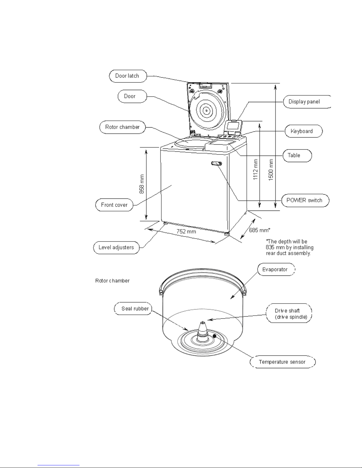
Refer to Figure 1-1 to identify the parts of the RC-6 PLUS.
Page 13
INTRODUCTION & DESCRIPTION
Centrifuge Description
Thermo Fisher Scientific RC-6 PLUS 1-3
Figure 1-1. Centrifuge Parts Location and Identification
Page 14

INTRODUCTION & DESCRIPTION
Centrifuge Specifications
1-4 RC-6 PLUS Thermo Fisher Scientific
Centrifuge
Specifications
Table 1-1. Centrifuge Specifications
Run Speed
*
*
Speed in revolutions per minute (rpm) is related to angular velocity, ω, according to the following:
Where = rad/s. All further references in this manual to speed will be designated as rpm.
Speed Selection Range (rpm) 300 to 22,000
Speed Control Accuracy ±25 rpm
Maximum Relative Centrifugal Force 52,200 x g
(F20MICRO)
Run Temperature
Temperature Selection Range -20°C to 40°C
**
**
The centrifuge will operate at ambient temperatures up to 40°C, but refrigeration system perfor-
mance may be less than optimal above 25°C.
After the centrifuge system has reached equilibrium. Ambient air temperature at the centrifuge air
inlets must be between 2°C to 40°C with maximum relative humidity of 80% at 31°C, linearly decreasing to 50% at 40°C. If the ambient air temperature is above 25°C, the centrifuge may not maintain low temperatures at high speeds, therefore, avoid areas near heat sources (for example, direct
sunlight, heating pipes and radiators). Also, avoid close grouping of centrifuges or other heat-producing laboratory equipment.
Temperature Control Range 2°C to 40°C
Temperature Control Accuracy ±2°C
Run Time Selection Range
1 minute to 99 hours, 59 minutes;
HOLD for continuous operation
Ambient Temperature Range 2°C to 40°C
***
Mass (Weight) 350 kg
Maximum Capacity 4,000 ml (SLC-4000)
Dimensions
Width 752 mm
Height to top of control console 1112 mm
Height with door open 1500 mm
Depth (including rear duct assembly) 835 mm
Depth (without rear duct assembly) 685 mm
From bottom to chamber inlet 858 mm
Noise Level <64 dB
****
Heat Output 3.7 kW (12,600 Btu/h)
*****
Page 15

INTRODUCTION & DESCRIPTION
Centrifuge Accessories
Thermo Fisher Scientific RC-6 PLUS 1-5
Centrifuge
Accessories
The following items are provided with the centrifuge:
***
After the centrifuge system has reached equilibrium. Ambient air temperature at the centrifuge
air inlets must be between 2°C to 40°C with maximum relative humidity of 80% at 31°C, linearly decreasing to 50% at 40°C. If the ambient air temperature is above 25°C, the centrifuge may not maintain low temperatures at high speeds, therefore, avoid areas near heat sources (for example, direct
sunlight, heating pipes and radiators). Also, avoid close grouping of centrifuges or other heat-producing laboratory equipment.
****
As measured with SE-12 rotor at 21,000 rpm (with compressor turned on) 3 feet from the front
of the unit and four feet from the floor.
*****
For the SS-34 rotor spinning 20,000 rpm at 4°C, after it has reached equilibrium. Other rotors,
speeds, and temperatures cause the heat output to vary.
Table 1-2.
Catalog No. Description
50105750 US Instruction manual
50105751 EU Instruction manual
Level
Rear duct assembly (To be mounted to the rear cover at
installation)
65937 Silicon grease
61556 Lubricant grease
Rotor cleaning bar
Page 16

INTRODUCTION & DESCRIPTION
Centrifuge Accessories
1-6 RC-6 PLUS Thermo Fisher Scientific
Page 17

Thermo Fisher Scientific RC-6 PLUS 2-1
Chapter 2 INSTALLATION
Installation or relocation of your centrifuge must be done by an authorized
Thermo Fisher Scientific representative. Contact Thermo Fisher Scientific or
your local representative of Thermo Fisher Scientific products.
After you receive your centrifuge, inspect it for damage before using it. The
RC-6 PLUS centrifuge must be installed in a location that meets all of the
electrical, location, and environment requirements that are specified below and
on the following pages. Installation instructions begin on page 2-3.
Inspection As soon as you receive your RC-6 PLUS Superspeed Centrifuge carefully
inspect it for any shipping damage that may have occurred. If you find any
damage, please report it immediately to the transportation company and file a
damage claim, then notify Kendro. If any parts are missing, contact one of the
Kendro district offices or the local representative of Thermo Fisher Scientific
products. You will find a list of offices on the back cover of this manual.
Identify the
Installation Site
DANGER
When servicing the centrifuge, be sure to turn off the POWER switch, turn off
the distribution board of your centrifuge room, and wait for at least three
minutes before removing covers or tables from the centri fuge to avoid ele ctrical
shock hazards.
WARNING
For operator safety, maintain a 30-cm "clearance envelope" around the
instrument and keep out of that area while the rotor is spinning. Do not store
dangerous substances capable of develo ping flamma ble or explos ive vapor s in
the clearance envelope.
Page 18

INSTALLATION
Identify the Installation Site
2-2 RC-6 PLUS Thermo Fisher Scientific
When choosing an installation site for the RC-6 PL US Centrifuge, consider its
dimensions, weight and noise level:
The location for the centrifuge must meet these requirements:
• A flat, vibration-free concrete floor. Avoid installing on a carpeted floor.
• Maximum altitude of 2000 meters.
• The unit is intended for indoor use only. Ambient air temperature at the
centrifuge air inlets must be between 2°C to 40°C with maximum relative
humidity of 80% at 31°C, linearly de cr ea sing to 50% at 40°C. If the ambient
air temperature is above 25°C, the centrifuge may not maintain low
temperatures at high speeds, therefore, avoid areas near heat sources (for
example, direct sunlight, heating pipes and radiators). Also, avoid close
grouping of centrifuges or other heat-producing laboratory equipment.
• Maintain a 30-cm clearance around the centrifuge. Do not store any
substances in the clearance envelope.
Note The RC-6 PLUS is a Class A product and is not intended for home use. If
used in a domestic environment you must contact your local authorities
for authorization.
Table 2-1.
Dimensions Width: 752 mm
Depth: 835m (including rear duct
assembly)
Depth: 685m (without rear duct assembly)
Height: 1112 mm
Weight 350 kg
Noise Level <64 dB (The maximum noise output with
the centrifuge, measured with the
compressor on at 0.91 m (3 ft) from the
front of the centrifuge and 1.22 m (4 ft)
from the floor.
Pollution Degree 2
Over Voltage Category II
WARNING
The RC-6 PLUS Centrifuge weighs 350 kg (772 lb.). Take the necessary
precautions when installing and moving the centrifuge to avoid personal injury
and/or damage to the centrifuge
Page 19

INSTALLATION
Leveling the Centrifuge
Thermo Fisher Scientific RC-6 PLUS 2-3
Figure 2-1. Clearances for the Centrifuge
Leveling the
Centrifuge
1. Turn on the centrifuge power and open the door. (If power supply is not yet
available, perform the Emergency Recovery from Power Failure procedure
discussed in Chapter 4.)
2. Place the level across the top of the drive spindle.
3. Using a 24 mm wrench, turn each of the four level adjusters until the casters
are 5 to 15 mm off the floor.
4. Level the unit by adjusting the level adjusters.
5. When the centrifuge is level, make sure each of the four level adjusters is
secure and rattle-free.
6. Secure each of the four level adjusters with the lock nuts.
CAUTION
Leave adequate space for airflow around the centrifuge and make sure no
vents are blocked. Blocking the airflow entering and/or exiting the centrifuge
can result in reduced performance, overheating and possible centrifuge
damage.
Page 20

INSTALLATION
Electrical Requirements
2-4 RC-6 PLUS Thermo Fisher Scientific
Figure 2-2. Leveling the Centrifuge
Electrical
Requirements
The appropriate power source must be available to plug in the centrifuge. The
power supply and outlet type required varies, depending on the rating on the
nameplate. Check the nameplate on the back panel of the centrifuge to
determine the electrical configuration of your centrifuge, which should be one of
the following:
CAUTION
The centrifuge can be damaged if it is connected to the wrong voltage, or if it is
connected to a line voltage that varies more than plus/minu s 10% of it s nominal
value. Check the voltage before plugging the centrifuge into any power source.
Thremo Fisher Scientific is not responsible for improper installation.
Table 2-2. Electric al Re qu ire m en ts
NAME PLATE RA TING SUPPLY REQUIRED
AC208/220/230/240
50/60Hz 21-24A single phase
AC208/220/230/240 50/60Hz 30A single
phase (25A single phase may be
acceptable depending on you local
electrical codes).
AC200 50/60Hz
25A single phase
AC200 50/60Hz 30A single phase
AC400 50/60Hz
2x15A 3 phase
AC400 50/60Hz 2x25A 3 phase
Page 21

INSTALLATION
Electrical Requirements
Thermo Fisher Scientific RC-6 PLUS 2-5
To connect to a different voltage, the centrifuge must be rewired and its plug
may also have to be replaced. Contact Thermo Fisher Scientific or your local
representative of Thermo Fisher Scientific products. For connection to a
different outlet, the power cord may also need to be replaced. Follow local
electrical codes.
Provide an emergency switch (circuit breaker) intended for the centrifuge only,
in case of emergency or in the event of failure. It is recommended that the
switch is located outside the centrifuge room or near the exit to the room.
Note For EMC emission the RC-6 PLUS is a Class A product. A slow reacting
circuit breaker is required because of the high startup current of the
compressor
Plug the power cord coming from the rear of the centrifuge in the terminal of the
distribution board. The green/yellow wire is a grounding wire. Your centrifuge
must be grounded properly.
Check the supply line voltage with a voltmeter and verify that the voltage
indicated on the nameplate is in agreement with the measured line voltage. If
the measured line voltage is not within 10% of the voltage specified on the
nameplate, do not connect the power cord and operate the centrifuge. Damage
to the centrifuge may result. To connect the centrifuge to a voltage other than
what is specified on the nameplate (including 3 phase), it will have to be rewired
and its power cord may have to be replaced. Contact Ther mo Fisher Scientific
to have an authorized Thermo Fisher Scientific representative do the rewiring.
Single phase RC-6 PLUS Centrifuges are equipped with a three- wire power
cord with three-prong connector to fit a NEMA 6-30P receptacle or equivalent
or, on 230V 50Hz centrifuges, an IEC 60309-type three-pin receptacle (32A,
2-pole and earth). 230V 50Hz poly phase RC-6 Centri fuge s ar e e quippe d with a
four-wire power cord with five-pin connector to fit an IEC 60309-type five-pin
receptacle (32 A, 3- pole, neutral and earth).
Provide an emergency switch (circuit breaker) intended for the centrifuge only to
turn off the centrifuge power in the event of failure. It is recommended to provide
that switch outside of the centrifuge room or near the exit of the centrifuge room.
WARNING
Your centrifuge must be grounded properly to avoid electrical shock hazards.
Page 22

INSTALLATION
Relocation
2-6 RC-6 PLUS Thermo Fisher Scientific
Relocation
Installation or relocation of your centrifuge must be done by an authorized
authorized Thermo Fisher Scientific representative. Contact Thermo Fisher
Scientific or your local representative of Thermo Fisher Scientific products.
Before relocating the centrifuge, unplug the centrifuge and loosen the locking
nuts. Lower the casters to the floor by turning the leveling bolts with a wrench.
Raise the leveling bolts enough to clear the floor and relocate the centrifuge.
After relocation, the centrifuge must be installed and leveled again.
CAUTION
Remove the rotor from the rotor chamber before relocating the centrifuge.
CAUTION
Be careful not to tip over the unit when moving on uneven or slanted floors.
Page 23

Thermo Fisher Scientific RC-6 PLUS 3-1
Chapter 3 CONTROLS, DISPLAYS
& INDICATORS
This chapter describes the RC-6 PLUS centrifuge controls, displays, and
indicators and includes their locations and functions.
Controls,
Displays, &
Indicators
The RC-6 PLUS control keyboard is used to select desired run parameters.
During a run, digital displays indicate set and actual run conditions, such as
estimated sample temperature, ro to r sp ee d , r ema inin g ru n tim e o r ac cu mu la te d
integral value.
Operation Panel The operation panel of the RC-6 PLUS Superspeed centrifuge is composed of a
display panel and function keys. The liquid cryst al disp lay can be tilted back and
forth for easy viewing. The display panel shows various screen displays such as
programmed operation, rotor list and user customization in addition to the basic
screen (RUN SCREEN) (see Figure 3-1).
The display automatically turns to the ZOOM SCREEN (see Figure 3-2) when
20 seconds have passed after reaching the set speed. The ZOOM screen
returns to the RUN SCREEN by pressing any key on the panel or when the rotor
starts deceleration.
Figure 3-1. Display Panel
Page 24

CONTROLS, DISPLAYS & INDICATORS
Operation Panel
3-2 RC-6 PLUS Thermo Fisher Scientific
Figure 3-2. Zoom Screen
Page 25

CONTROLS, DISPLAYS & INDICATORS
Operation Panel
Thermo Fisher Scientific RC-6 PLUS 3-3
Table 3-1.
No Name Display Panel Function (refer to Figure 3-1)
1 Field display Displays the following run conditions.
For SPEED, TIME and TEMP displays, the upper line
shows the actual run state and the lower line shows
the set value. Refer to Setting Run Conditions for
details.
• SPEED (Speed display)
(Upper line)
Displays rotor speed in increments of 10 rpm under
10,000 rpm and increments of 100 rpm over 10,000
rpm.
(Lower line)
Displays rotor speed in increments of 10 rpm under
10,000 rpm and increments of 100 rpm over 10,000
rpm. Set speed range is from 300 rpm to 21,000
rpm.
• TIME (Run time display)
(Upper line)
Displays remaining run time during operation. If
HOLD is selected, displays elapsed run time.
(Lower line)
Run time range is from 1 minute to 99 hours, 59
minutes in increments of 1 minute.
• TEMPERATURE (Temperature display)
(Upper line)Displays rotor temperature in
increments of 1 degree centigrade.
(Lower line)Temperature range is from - 20
degrees centigrade to 40 degrees
centigrade in increments of 1 degree centigrade.
• ACCEL (Acceleration rate display)
Displays 1 to 9 acceleration rates.
• DECEL (Deceleration rate display)
Displays 1 to 9 deceleration rates and free coast
(0).
Page 26

CONTROLS, DISPLAYS & INDICATORS
Operation Panel
3-4 RC-6 PLUS Thermo Fisher Scientific
Figure 3-3. Function Keys
2 FU NCTION
field
• PROG Used to save run conditions for
programmed operation.
• RCF Used to display and set RCF value.
• ω
2
T Used to display and set for integrator
operation.
3 Message
indicator
Displays alarm message, prompt and rotor model.
4 RUN mode
indicator
Displays operating mode with illustration of a rotor.
Operating modes are as follows:
STOP, ACCEL, RUN (Displayed when rotor is
rotating at set speed), DECEL
And DELAY (Displayed up to RTC operation is
started)
Table 3-1.
No Name Display Panel Function (refer to Figure 3-1)
Table 3-2.
No Name Key Function (refer to Figure 3-3)
5 START key Starts the centrifuge run.
6 STOP key Stops the centrifuge run.
7ROTOR
key
Used to display rotor list or to enter desired rotor
number.
8 ESC key Used to return to the previous screen. (e.g., from
MENU screen to RUN SCREEN)
9 MENU key Displays MENU screen.
You can select user customization, or alarm
information.
Page 27

CONTROLS, DISPLAYS & INDICATORS
POWER Switch
Thermo Fisher Scientific RC-6 PLUS 3-5
POWER Switch The POWER switch is located in the upper right-hand corner of the front cabinet
panel. The switch is an ON/OFF toggle switch, when set to ON applies electric
power to the centrifuge.
" I " : ON
" O " :OFF
10 Cursor keys
(1) Makes the RUN SCREEN ready-to-enter state.
(2) Moves the cursor on the screen.
1. Moves the cursor upward (K).
2. Moves the cursor left (I).
3. Moves the cursor right (J).
4. Moves the cursor downward (L).
11 Ten-key Used to set run conditions with numeric values.
numerical
pad
At time setting : switches between hours and
minutes.
At temperature setting : Used to enter a minus
sign.
At ω
2
T value setting : switches between integer
and mantissa.
At run time setting: used to set continuous
operation.
Used to clear typing errors and alarm messages.
(1) By pressing the CE key, the entered value on the
line where the cursor stays is cleared and the
cursor returns to the previous position.
(2) By pressing the CE key, displayed alarm
message is cleared. If two or more alarm
messages are displayed at a time, clear them
one by one. (Refer to Corrective Actions for
details.)
Used to fix the entered value.
Table 3-2.
No Name Key Function (refer to Figure 3-3)
CAUTION
Always keep the liquid crystal panel in a visible position while the POWER
switch is turned on so that you can check the current operating state.
Page 28

CONTROLS, DISPLAYS & INDICATORS
Diagnostic Indicators Safety Device
3-6 RC-6 PLUS Thermo Fisher Scientific
Do not position the centrifuge so that the movement of the POWER switch may
become difficult.
Figure 3-4. POWER switch
Diagnostic
Indicators Safety
Device
Protection of Rotor Chamber The rotor chamber allows the rotor to rotate at high speeds. A steel protector is
provided around the chamber for the operator’s safety in case of any rotor
mishap during centrifugation.
Imbalance Detector This centrifuge is equipped with a sensor that detects severe vibration of the
rotor due to improper bucket setting or excessive imbalance, and decelerates
the rotor. If an imbalance is detected, the run will be terminated and
IMBALANCE will be displayed.
Door Lock For safety reasons, the door is automatically locked while the rotor is rotating.
The locked state is held even if the instrument power is turned off. The door can
be opened/closed only when the rotor stops.
Page 29

Thermo Fisher Scientific RC-6 PLUS 4-1
Chapter 4 OPERATION
This chapter provides step-by-step instructions on how to set the centrifuge
power ON, open the chamber door, and perform a run in the normal mode. It
also describes how to precool the rotor. Read and observe the Important Safety
Information supplied on page iii at the front of this manual.
The chapter contains supplementary information on how to calculate relative
centrifugal force (RCF); how to do a test run for low speed and low temperature
operation; and what will cause an ENTRY ERROR.
The controls and displays referred to in this chapter are described in detail in
Chapter 3.
Reducing Speed
for Loads in
Excess of Design
Mass
Each rotor has a maximum allowable compartment mass (defined in Appendix
and in the rotor manual). To prevent rotor failure, the total contents of any
compartment, including specimen, tubes, sealing assembly and adapters must
not exceed the specified maximum compartment mass unless rotor speed is
reduced proportionately. Strict adherence to the maximum allowable
compartment mass or reduced rotor speed is required to pr event rotor failure.
If the maximum compartment mass is greater than value specified for the rotor,
use the following formula to determine the redu ce d ro to r sp ee d re qu ire d :
WARNING
1. Use specified Thermo Fisher Scientific rotors only.
2. Do not use corroded, scratched or cracked rotors, buckets and assemblies.
Check that the rotor, buckets and assemblies are free of such abnormalities
before operation.
3. Do not exceed the maximum rated speed of the rotor or buckets in use.
4. Failure to reduce rotor speed when compartment load exceeds maximum
allowable compartment load can lead to rotor failure and result in personal
injury and/or centrifuge damage.
Page 30

OPERATION
Basic Operation
4-2 RC-6 PLUS Thermo Fisher Scientific
Basic Operation
This section describes how to perform a basic run, how to set run conditions on
the RUN SCREEN and how to use the cursor keys.
1. Set the main power switch ON.
2. Open the chamber door.
3. Install the rotor:
• Wipe the rotor centerhole and spindle surfaces clean to reduce the chance
of the rotor sticking to the spindle.
• If applicable, make sure the rotor cover is installed.
• Place the rotor on the drive spindle and lock it in place turning the rotor
locking knob counterclockwise.
4. Close the chamber door.
5. Set the Run Screen as follows.
WARNING
1. Failure to load and install the rotor in accordance with the instructions in the
rotor operating guide could result in damage to the centrifuge. The rotor cover
must be on and locked in place and the rotor must be locked on to the drive
spindle.
2. Use specified Thermo Fisher Scientific rotors ONLY.
3. Do not incline or move the instrument while the rotor is spinning.
4. Do not place any object on the instrument or lean on the instrument while the
rotor is spinning.
Page 31

OPERATION
Basic Operation
Thermo Fisher Scientific RC-6 PLUS 4-3
RUN Screen
The RUN SCREEN shows the set and actual run conditions.
The speed (SPEED), time (TIME) and temperature (TEMP) displays have a
two-line display.
The upper line shows the actual run state and the lower line shows the set
value.
The acceleration (ACCEL) and deceleration (DECEL) displays show the set
value.
Figure 4-1. RUN Screen
CAUTION
1. Do not tilt the display panel forcibly or, mechanical components can be
damaged.
2. Do not press the function keys with a sharp-pointed object such as a ballpoint
pen.
3. If an abnormal sound is heard during the operation, stop the operation
immediately and contact Thermo Fisher Scientific or your local representative
of Thermo Fisher Scientific products.
WARNING
Do not leave rotors or other objects on centrifuge surfaces during operation.
Page 32

OPERATION
Basic Operation
4-4 RC-6 PLUS Thermo Fisher Scientific
Cursor Keys A cursor appears and blinks on the entry line of a run condition display by
pressing a cursor key as shown in Figure 4-2.
The entry line state varies depending on the presence of cursor as shown
below.
1. Fixed-entry state: No cursor appears in normal state.
2. Ready-to-enter state: By pressing any of the four cursor keys in fixed-entry
state, a cursor appears blinking "0" (or other numeric value) on the entry
line. Desired numeric values can be entered in this state. Press the cursor
keys to move the cursor.
To set desired run conditions, put the RUN SCREEN in the ready-to-enter state.
Move the cursor to the desired item and enter a numeric value. If no numeric
value is entered in ready-to-enter state for 30 seconds or more, the display
automatically turns to fixedentry state.
Note To enter desired value when the entry line is fixed-entry state (e.g., the
state of RUN SCREEN after turning on the POWER switch), press any of
the four cursor keys to show a blinking cursor and move the cursor to the
desired item with cursor keys. The cursor keys have two functions. One
is to show a cursor on the screen and the other is to move the cursor. The
cursor on the screen can be moved up, down, left and right according to
the arrow marks on the cursor keys.
Figure 4-2. Entry Line State
Designating the Rotor Before operation, the roto r used must be design ated according to the following
procedure. This centrifuge does not start operation unless a rotor is designated.
This centrifuge performs optimum temperature compensation and maximum
speed checking for the designated rotor.
Page 33

OPERATION
Basic Operation
Thermo Fisher Scientific RC-6 PLUS 4-5
1. When setting two or more run conditions, there is no need to press the
ENTER key after each setting. The set value is entere d by pressing a cursor
key and the cursor moves to the new item in ready-to-enter state.
2. If changing the TIME setting during continuous operation (HOLD), enter a
value adding the desired remaining time to the elapsed time. For example,
to stop the operation after 1 hour and 30 minutes when 5 hours have
elapsed in continuous operation, turn the TIME display to ready-to-enter
state by pressing a cursor key and enter as follows.
Setting RUN Conditions The table below exemplifies how to set run conditions such as rotor speed, run
time and rotor temperature.
Table 4-1.
Step Key Operation Screen Display and Notices
1
Press the ROTOR key on the
KEY BOARD.
Enter the rotor number to be
used with the ten-key numerical
pad and press the NTER key.
(The screen turns to the next
page by pressing the cursor key.)
The screen returns to the RUN
SCREEN.
Page 34

OPERATION
Basic Operation
4-6 RC-6 PLUS Thermo Fisher Scientific
Table 4-2. Set Run Conditions
Item
Example set value
Speed (SPEED)
20,000 rpm
Run Time (TIME)
2 hours, 30 minutes
Procedure
1
Press a cursor to turn the display
to ready-to-enter state.
The display turns to
readyto-enter state.
The display turns to
ready-to-enter state.
2
Move the cursor to the desired
item by pressing the cursor keys.
(The arrow marks on the cursor
keys indicate cursor directions.)
3
The cursor blinks on the entry
line for 30 seconds.
The display is now ready-to-enter
state.
4
Enter the desired value with
the ten-key numerical pad.
Entered numerals are shifted to
the left in order.
The last zero (0) need not
be entered.
The cursor can be moved to the
hours setting position by pressing
the cursor left key.
For continuous run, press the
HOLD key.
5
Check the setting and fix it by
pressing the ENTER key.
Setting can also be fixed by
pressing a cursor key. The CE
key is used to cancel the setting.
The speed setting is "20,000
rpm".
The run time setting is "2:30
(2 hours 30 minutes)".
6
Press the START switch.
7
After the rotor has come to a
stop, lift the door handle. Then
remove the rotor.
Setting range
300 rpm to the maximum speed:
in increments of 10 rpm under
10,000 rpm, and in increments of
100 rpm over 10,000 rpm
1 minute to 99 hours 59 minutes:
in increments of 1 minute
Page 35

OPERATION
Basic Operation
Thermo Fisher Scientific RC-6 PLUS 4-7
Note Keep the chamber door closed af ter the roto r has been r emoved to inhibit
the formation of condensation on the chamber walls.
To repeat the run with the same speed, time and temperature parameters,
install the rotor, close the chamber door, press START and then press ENTER.
Table 4-3. Speed, Time and Temperature Parameters
Temperature (TEMP)
4 degrees centigrade
Acceleration Rate (ACCEL) 9Deceleration Rate (DECEL)
7
The display turns to
ready-to-enter state.
The display turns to
ready-to-enter state.
The display turns to
ready-to-enter state.
The cursor is blinking at the single
digit position.
Enter "0" for selecting free coast.
The temperature setting is "4
degrees centigrade".
The acceleration rate setting is
"9".
The deceleration rate setting is
"7".
-20 degrees centigrade to 40
degrees centigrade: in increments
of 1 degree centigrade
1 to 9 1 to 9 and 0 for free coast
Page 36

OPERATION
Normal Operating Procedure
4-8 RC-6 PLUS Thermo Fisher Scientific
Normal Operating
Procedure
This section describes the procedure for normal operation.
Note Before following the procedur e, read the rotor instr uction manual carefully
and make sure that you have selected the appropria te type of tube for the
sample, and that the amount of sample in the tubes is correct.
The RUN mode indicator is displayed on the panel as follows:
Table 4-4.
Step Procedure State of Centrifuge and Notices
1
Turn ON the POWER
switch of the centrifuge.
• The panel indicators turn on.
• The door lock is released.
2 Mount the rotor.
• Mount the rotor on the drive spindle
properly and tighten the rotor locking knob
securely.
• Press the ROTOR key and enter the
correct rotor number.
3 Set run conditions.
• Set run conditions referring to Set Run
Conditions.
4 Press the START key.
• The rotor starts rot ating and the timer star ts
counting.
• The rotor accelerates up to the set speed.
5
The set run time has
elapsed or the STOP key
is pressed.
• The rotor starts decelerating.
6 The rotor stops.
• The centrifuge makes a beep to notify that
the rotor has stopped.
7 Remove the rotor.
• Wait until the rotor stops completely and
then remove the rotor.
Page 37

OPERATION
Normal Operating Procedure
Thermo Fisher Scientific RC-6 PLUS 4-9
Figure 4-3. RUN Mode Indicator
Acceleration Rate and
Deceleration Rate
The acceleration and deceleration rates can be adjusted for a wide range of
use. The figure below shows how a rotor accelerates and decelerates in
compliance with a code number selected from 1 through 9.
Note These time values vary with the type of rotor in use.
Table 4-5. Acceleration Rate and Deceleration Rate
Code No. Time for acceleration from
0 to 500 rpm
Time for deceleration from
500 to 0 rpm
9 Minimum
*
*
The minimum time is the one that occurs when the rotor is being accelerated
or decelerated with the maximum torque of the driving motor. This time varies
with the type of rotor in use.
Minimum
**
**
The minimum time is the one that occurs when the rotor is being accelerated
or decelerated with the maximum torque of the driving motor. This time varies
with the type of rotor in use.
8 30 sec. 1 min.
7 45 sec. 2 min.
6 1 min. 3 min.
5 2 min. 4 min.
4 3 min. 6 min.
3 4 min. 8 min.
2 6 min. 10 min.
1 10 min. 15 min.
0 - Coasting deceleration from set
speed
Page 38

OPERATION
Normal Operating Procedure
4-10 RC-6 PLUS Thermo Fisher Scientific
Figure 4-4. Acceleration and Deceleration Rates
FUNCTION Field
Figure 4-5. Function Field
The RC-6 Plus Superspeed centrifuge has many add-on features such as
programmed operation and centrifugal force values displaying and setting.
These features are displayed and selected on the FUNCTION field.
PROG : You can save run conditions in memory for later use in repeated
operation.
This feature also allows step-mode operation (three normal operations can be
combined in a sequence of operations).
RCF : The centrifuge automatically computes and displays RCF values from set
speed, or speed from set RCF values.
ω
2
T : The centrifuge automatically computes and displays run time from set
speed and ω
2
T set value.
Programmed Operation Programmed operation capability is an add-on feature that saves set run
conditions in memory for later use. This feature allows you to save frequently
used run conditions in memory and then recall the saved run conditions
whenever you need them, thus making the operation procedure simple. (Even
when the POWER switch is turned off, the saved run conditions remain in
memory.) The memory in the centrifuge can contain 30 sets of run parameters.
Page 39

OPERATION
Saving and Changing Run Conditions
Thermo Fisher Scientific RC-6 PLUS 4-11
Saving and
Changing Run
Conditions
To save or change run conditions in memory, use the following procedure.
Table 4-6. Change Run Conditions in Memory
Step Key operation Screen display and notices
1 Move the cursor to
PROG and press
the ENTER key.
The FUNCTION field turns to the PROGRAM
field.
2 Press the cursor
key to move the
cursor to SAVE
and press the
ENTER key.
The screen turns to the MEMORY No. LIST
screen.
A setting parameter of the RUN SCREEN is
temporary saved at first memory area.
3 Enter the desired
MEMORY No. to
be saved with the
ten-key numerical
pad and press the
ENTER key.
(e.g.: saving run
conditions at
MEMORY No.1)
The cursor moves to the desired MEMORY No.
Page 40

OPERATION
Saving and Changing Run Conditions
4-12 RC-6 PLUS Thermo Fisher Scientific
4 When other
conditions are
saved, selecr the
desired memory
No. (.g.: at
MEMORY NO.2)
And enter run
conditions as
follows.
e.g.: SPEED:
20,000 rpm
TIME: HOLD
TEMP: 4 degrees
centigrade
ACCEL: 9
DECEL: 7
ROTOR No.: 25
(F20/MICRO)
The run conditions are saved at MEMORY No. 2.
* The screen turns to RCF and g.sec values entry
screen by pressing the cursor key.
Table 4-6. Change Run Conditions in Memory
Step Key operation Screen display and notices
Page 41

OPERATION
Saving and Changing Run Conditions
Thermo Fisher Scientific RC-6 PLUS 4-13
Note 1. When the saved run conditions are changed, the previous run
conditions are cleared and the newly saved run conditions are in effect.
2. Run conditions cannot be saved while the rotor is rotating. Check that
the rotor stops completely before saving run conditions.
Using Programmed Operation To recall the saved run conditions and use programmed operation with the
recalled run conditions, take the following procedure.
5 After saving run
conditions, press
the ESC key twice.
*The PROGRAM field appears by the first press
of the ESC key.
*The FUNCTION field appears by the second
press of the ESC key.
Table 4-6. Change Run Conditions in Memory
Step Key operation Screen display and notices
Page 42

OPERATION
Step-mode Operation
4-14 RC-6 PLUS Thermo Fisher Scientific
Table 4-7. Recalled Run Conditions
Step-mode
Operation
This centrifuge has the step-mode operation capability that allows you to save
three different sets of values for a ru n p arameter set in a single memory location
(MEMORY Nos. 31 - 33, 41 - 43, and 51 - 53) and then change some or all of
Step Key operation Screen display and notices
1 Move the cursor to
PROG and press
the ENTER key.
The FUNCTION field turns to the PROGRAM
field.
2 Press the ENTER
key when the
cursor stays on
CALL.
The screen turns to the MEMORY No. LIST
screen.
3
Enter the desired
MEMORY No. with
the ten-key
numerical pad and
press the ENTER
key. (e.g.: r ecalling
run conditions
saved at
MEMORY No. 2
)
The recalled run conditions are displayed.
The MEMORY No. appears on the message display.
Only the saved MEMORY No. can be recalled
.
4 Mount the rotor
and press the
START key.
* The rotor starts rotating.
* When reentering (changing) a run condition of the
recalled MEMORY No. (e.g., SPEED), the MEMORY
No. is canceled.
Recall the MEMORY No. again if necessary.
* The MEMORY No. cannot be changed (or recalled)
while the rotor is rotating.
Page 43

OPERATION
Step-mode Operation
Thermo Fisher Scientific RC-6 PLUS 4-15
the run conditions (e.g., speed, run time, rotor temperature, etc.) for each step
during a step-mode run. Save step-mode run conditions at the MEMORY Nos.
31 - 33 (41 - 43 or 51- 53) in accordance with "3-3-1 Programmed Operation
(1)".
When the MEMORY No. 31 is recalled, the centrifuge automatically performs
step-mode operation in order of MEMORY Nos. 31, 32 and 33.
Procedure for step-mode
operation
[Example]
The table below shows the run parameters and their values required for an
example 3-step run (MEMORY Nos. 31 to 33) . Fig. 4-6 depict s how the example
run will proceed.
Figure 4-6. Details of an example step-mode operation
Note (1) Select the same rotor number for each step. Otherwise, alarm
message "ROTOR NO." is indicated and the centrifuge stops operation.
(Contents of the memory cannot be called up.)
Table 4-8. Example 3-Step Run
1st step
(Memory No.
31)
2nd step
(Memory No.
32)
3rd step
(Memory No.
33)
Speed
1000rpm 2000rpm 5000rpm
Run time
30min 60min 10min
Temperature
4°C 4°C 4°C
Accel rate
999
Decel rate
997
Rotor No.
46
46 46
Page 44

OPERATION
RTC (Real Time Control) Operation
4-16 RC-6 PLUS Thermo Fisher Scientific
Note (2) Use the MEMORY Nos. 32 and 33 (42 and 43 or 52 and 53) for the
step-mode operation with two steps.
RTC (Real Time
Control) Operation
The RC-6 Plus Superspeed Centrifuge can be programmed to perform
automatic centrifugation by setting the incorporated time clock to start and end
centrifugation at the desired time in advance. This is the RTC (Real Time
Control) operation, also referred to as delayed start/stop.
Figure 4-6 illustrates an example of procedure for RTC operation.
Example: The rotor is loaded in the centrifuge and the run conditions listed
below are set in the evening on April 1, to end the operation about 9:30 a.m.
next morning.
Figure 4-7. Example of RTC Operation
In this example, the above run conditions from (2) to (6) are set first and then
the designated time to complete the RTC operation, 9:30 a.m. on April 2. Then
the START key is pressed.
(Otherwise, the same RTC operation can be achie ved b y se tting the desig nated
time to start centrifugation, 8:30 a.m. on April 2.)
Table 4-9. Example of RTC Operation
1 Rotor SS-34
2 Speed 18,000 rpm
3 Run time 60 minutes
4 Temperature 4 degrees centigrade
5 Acceleration rate 9
6 Deceleration rate 7
Page 45

OPERATION
RTC (Real Time Control) Operation
Thermo Fisher Scientific RC-6 PLUS 4-17
Procedure for RTC Operation
Step Key operation Screen display and notices
1 Set the run
conditions.
• Set the run conditions referring to Setting Run
Conditions.
• For time setting, do not select HOLD but enter a
numeric value.
2 Move the cursor to
PROG and press
the ENTER key.
The FUNCTION field turns to the PROGRAM field.
3 Press the cursor
key three times to
move the cursor to
RTC and press the
ENTER key.
The screen turns to the RTC operation setting screen.
4 Select the desired
item.
When selecting "1:
Setting stop time",
press the following
keys.
The cursor is blinking on "day" column.
The date (month and day) is automatically display
ed.
Page 46

OPERATION
RTC (Real Time Control) Operation
4-18 RC-6 PLUS Thermo Fisher Scientific
5
Enter the desired
date and time
(month, day, hour
and minutes) using
the cursor keys and
the ten-key numerical pad. Press the
ENTER key.
• The range for "hour" setting is from 0 to 23
(24-hour display).
• Do not enter any date and time that passed
the current time.
Set a proper stop time considering the
centrifugation time so that the start time will be
later than the current time.
• It is not possible to set an operation that will
start 20 days or more from the current time.
6
Select Yes or No in
response to the
prompt.
• When selecting "Yes":
• The screen turns to the RUN SCREEN and the
RTC time is displayed.
• RTC appears on the message indicator.
• When selecting "No", the display turns to the
screen of Step 2
. Enter the desired setting
again.
Step Key operation Screen display and notices
Page 47

OPERATION
RTC (Real Time Control) Operation
Thermo Fisher Scientific RC-6 PLUS 4-19
1. The RUN mode indicator on the panel turns as follows in RTC operation.
Figure 4-8. Operating Mode (RTC)
2. Note that the RTC setting is not available in the following cases:
i. The time setting on the RUN SCREEN is "HOLD" (continuous run).
Change the run time setting from "HOLD" to a desired numeric
value.
ii. The start time has already passed.
Change the setting so that the start time will be later than the
current time.
iii. The start time is 20 days or more from the current time.
Change the setting so that the start time will be within 20 days.
7 Check the RTC
setting on the
RUN SCREEN
and press the
START key.
• Perform operation according to Operating
Procedure.
• Note that the run time setting cannot be changed
after setting the RTC operation. Clear the RTC
setting and then reset the run time if necessary.
• The centrifuge turns to "DELAY" mode by pressing
the START key and wait until the set time. The
centrifuge automatically starts operation at the set
time and keeps operation during the designated
time.
• The RUN mode indicator on the message displa y
turns to "DELAY".
Step Key operation Screen display and notices
Page 48

OPERATION
Displaying and Setting RCF
4-20 RC-6 PLUS Thermo Fisher Scientific
3. Clear the RTC setting and then reset the run time if it is necessary to
change the run time setting after setting the RTC operation.
4. Recall the saved run conditions and enter the RTC setting when performing
the programmed operation (including the step-mode operation) and the
RTC operation in combination. The centrifuge automatically computes the
total run time of all steps in the programmed operation and also the start
time for RTC operation. Note that the saved run conditions cannot be
recalled after setting the RTC operation.
5. Press the STOP key to stop the operation. The RTC operation is stopped
and the rotor stops.
6. When performing the RCF operation and the RTC operation in combination,
enter the RCF setting first then enter the RTC setting. (See Displaying and
Setting RCF.)
7. When performing the ω
2
T operation and the RTC operation in combination,
enter the ω
2
T setting first then enter the RTC setting. (See Displaying and
Setting
ω
2
T.)
Displaying and
Setting RCF
The RC-6 Plus Superspeed centrifuge, has in its internal memory, data
representing the maximum radii of all available rotors. Based on this data, the
centrifuge automatically computes relative centrifugal force (RCF) values from
set speed, or speed from set RCF values, and then displays the result on the
control panel. This section explains how to use this RCF displaying and setting
capability of the centrifuge.
Page 49

OPERATION
Displaying and Setting w2T
Thermo Fisher Scientific RC-6 PLUS 4-21
Table 4-10. Use of RCF Displaying and Setting
1. Press ESC key to clear the RCF screen.
2. The RCF operation is canceled by changing the set speed or changing the
operation mode to the programmed operation mode.
Displaying and
Setting ω2T
This machine is provided with a function to perform an integrator (ω2T)
operation. To perform an ω
2
T operation, set the ω2T value instead of the run
time.
Step Key operation Screen display and notices
1 Move the cursor to
PROG and press
the ENTER key.
The FUNCTION indicator turns to the RCF display.
RCF(Upper line).
Displays the actual RCF computed for the
motor speed and selected rotor.
(Lower line) Set RCF
Displays the set RCF computed for the motor
speed and selected rotor.
2 Enter the desired
RCF with the
ten-key numeric
pad and press the
ENTER key.
The RPM is computed from the set RCF and selected
rotor is
displayed.
Set RCF
Page 50

OPERATION
Displaying and Setting w2T
4-22 RC-6 PLUS Thermo Fisher Scientific
Step Key operation Screen display and notices
1 Set the speed in
the Run Screen.
See Basic Operation.
2 1. Use cursor
keys to move
cursor to ω
2
T
on the RUN
SCREEN.
2. Press the
ENTER key.
The FUNCTION indicator turns to the ω
2
T set screen.
3 Enter a desired
ω
2
T value.
Example: 9.87E11
Entered value is displayed on the ω2T SET column and
the message indicator respectively.
The TIME display shows “- : -“.
Set ω2T
4 When you press
START key, the
run is controlled by
the set ω2T value
rather than by
time.
Computed and integrated value is displayed on the ω
2
T
indicator.
Page 51

OPERATION
Emergency Recovery from Power Failure
Thermo Fisher Scientific RC-6 PLUS 4-23
Note When the displayed ω
2
Treaches the set value of ω2T, the machine
decelerates and stops. During deceleration,ω
2
T is integrated and its result is
displayed until a stop.
w
2
T is selectable between 0.01E03 and 9.99E17.
The w
2
T operation is canceled by changing the set time or changing the
operation mode to the programmed operation mode. When the FUNCTION
indicator shows the w
2
T mode, the w2T mode is canceled and no value is
indicated on the w
2
T SET column by changing the set time.
The w
2
T indicator shows the current w2T value computed during operation.
Note When performing the RTC operation and the ω
2
T operation in
combination, following phenomenon may occur due to a conversion error from
the set ω
2
T to the run time. (There is no error in operation for the set ω2T.)
Emergency
Recovery from
Power Failure
Table 4-11. Conversion Error in RTCOoperation
RTC Setting Phenomenon
When setting the operation start
time
Actual operation does not start at
the displayed time exactly.
When setting the operation end time Actual operation does not end at the
displayed time exactly.
WARNING
When servicing the centrifuge, be sure to turn off the POWER switch, turn off
the distribution board of your centrifuge room, and then wait for at least three
minutes before removing covers or tables from the centrifu ge to avoid electr ical
shock hazards.
Page 52

OPERATION
Emergency Recovery from Power Failure
4-24 RC-6 PLUS Thermo Fisher Scientific
Rotation of Rotor The rotating rotor coasts free and finally stops if a power failure occurs during
operation. When the power is restored, the centrifuge automatically
re-accelerates the rotor if the rotor is still rotating at 250 rpm or higher, or
decelerates the rotor if the rotor is rotating under 250 rpm.
Operation Panel
During the power failure, all the displays on the display panel are off. When the
power is restored, the centrifuge will restart the control of the run with the set
parameters that were in effect before the power failure (battery-backed), and
will report the occurrence of the power failure by lighting up the alarm message.
Removing the Rotor During
Power Failure
If the power failure continues for an extended time, and you have decided to
remove the rotor from the rotor chamber during the power failure, use the
following procedure.
The rotor needs more than 60 minutes to co ast to a complete stop if the rotor
has been rotating at high speed.
1. Check that the rotor stops completely.
WARNING
Never attempt to open the door while the rotor is rotating.
Never attempt to slow or stop the rotor by hand.
WARNING
Make sure that the rotor has coasted to a complete stop. When the rotor is at
rest, it makes no sound. So listen carefully for any sound coming from the rotor
chamber.
Never attempt to override the door interlock system while the rotor is rotating.
CAUTION
Do not perform any operation not specified in this manual. If any problem is
found with your centrifuge, contact Thermo Fisher Scientific or your local
representative of Thermo Fisher Scientific products.
Page 53

OPERATION
Emergency Recovery from Power Failure
Thermo Fisher Scientific RC-6 PLUS 4-25
2. Turn off the POWER switch of the centrifuge and the distribution board of
your centrifuge room.
3. Remove the two screws from the lower portion of the front cover. Remove
the front cover by pulling the lower portion of the front cover forward and
downward. The upper portion of the front cover is not secured with screws.
4. Raise the weights of the two door locks at the front and secure them with
adhesive tape.
Figure 4-9. Opening the Door
5. Release the door handle and open the door slowly.
Check that the rotor has stoped completely. If the rotor is rotating, close the
door immediately.
Page 54

OPERATION
Features on Menu Screen
4-26 RC-6 PLUS Thermo Fisher Scientific
6. Take out the rotor and remove the adhesive tape from the door lock
solenoids.
Insert the hooks into the square holes and put the front cover on the
support, then secure the front cover with the screws in the reverse order of
removal.
Features on Menu
Screen
WARNING
Never attempt to slow or stop the rotor by hand.
Table 4-12. Features on Menu Screen
Features on Menu Screen
Press the MENU key and a menu
appears as follows.
(1) User customization
(2) Alarm information
Select the desired item with the
numeric key and press the ENTER
key to show the corresponding
screen.
User Customization
The user customizations include the
following items.
(1) Screen utilities
(2) Precool
(3) Melody
Select the desired item with the
numeric key and press the ENTER
key to show the corresponding
screen.
Page 55

OPERATION
Features on Menu Screen
Thermo Fisher Scientific RC-6 PLUS 4-27
Screen Utilities
You can customize the unit’s time
setting, screen contrast level, and
run screen.
Changing RUN SCREEN
1 = NORMAL RUN SCREEN is
displayed.
2 = ZOOM: The display
automatically turns to ZOOM
screen when 20 seconds have
passed after reaching the set
speed. The ZOOM screen
returns to the RUN SCREEN by
pressing any key on the panel or
when the rotor starts
deceleration.
Changing Date and Time
This feature is used when adjusting
the incorporated time clock to
the current date and time
correctly.
Set the correct date and time for
RTC Operation.
Enter the desired date and time
using the cursor keys and the
ten-key numerical pad, then
press the ENTER key.
Screen Contrast
Use cursor keys to adjust the
contrast.
Enter the desired date and time
using the cursor keys and the
ten-key numerical pad, then
press the ENTER key.
Note Press the ESC key return to
the RUN SCREEN.
Note The cursor disappears from
the screen after the keyboard is
idle for more than 30 seconds.
Press a cursor key to show the
cursor on the screen.
Table 4-12. Features on Menu Screen
Page 56

OPERATION
Lockout system function (optional)
4-28 RC-6 PLUS Thermo Fisher Scientific
Lockout system
function
(optional)
The lockout system function is specifically designed for the RC-6 PLUS
centrifuge. This lockout system is used to limit the users of the centrifuge. The
registered users can use this system after the system administrators have
registered the users.
It is necessary for the system administrators to read the separated manual
“RC-6 PLUS LOCKOUT SYSTEM INSTRUCTION MANUAL”. The users are
required to log on to the centrifuge by inputting the ID code and the password
on the initial screen of the lock out system to op era te the c entrifu ge. After usin g
the centrifuge, be sure to log off the lock out system or turn off the main power
switch. This section describes the procedure for the lock out system operation.
Precool
The temperature in the chamber is
controlled at about 15 degrees
centigrade if the door is closed and
Precool is selected.
(The temperature in the chamber
may not hold at 15 degrees
centigrade if the ambient
temperature or the temperature of
the
evaporator is 15 degrees centigrade
or less.)
Melody
You can select a desired melody
from one tune, a beep, or beep off
(silence) with the numeric key. Press
the ENTER key after selection.
Alarm Information
Alarm information and remedies are
displayed on the ALARM
INFORMATION screen.
This feature allows you to cope with
troubles that occurred during
operation. Refer to Troubleshooting
for details.
Table 4-12. Features on Menu Screen
Page 57

OPERATION
Lockout system function (optional)
Thermo Fisher Scientific RC-6 PLUS 4-29
Table 4-13. Lockout System
Step Key operation Screen display and notices
1 When using the lockout system,
turn on the main power switch.
Then the initial screen of the
lockout system is displayed.
Input your (registered user) own
ID code (4digits) and press the
ENTER key.
Then input the password(4digits)
and press the ENTER key.
2 The screen shown in the right
figure is displayed. (This screen
is displayed when using the RC-6
PLUS centrifuge.) The centrifuge
is now operable.
3 Logged on user name can be
displayed.
Press the cursor key to move the
cursor to “LOCK OUT” in the
FUNCTION box and press the
ENTER key.
Page 58

OPERATION
Lockout system function (optional)
4-30 RC-6 PLUS Thermo Fisher Scientific
4 After using the centrifuge, log off
the lockout system according to
the following procedure.
(The lockout system can also be
logged off by turning off the main
power switch.) The lockout
system is not available next time
if this procedure is not
performed.
Press the cursor key to move the
cursor to “LOCK OUT” in the
FUNCTION box and press the
ENTER key.
Press the cursor key to move
the cursor to “LOG OFF” and
press the ENTER key. Then the
initial screen of the lockout
system is displayed(same as the
above step1)
Step Key operation Screen display and notices
Page 59

Thermo Fisher Scientific RC-6 PLUS 5-1
Chapter 5 CARE AND
MAINTENANCE
This section describes routine maintenance activities to ensure your centrifuge
remains in good operating condition. We also recommend that you have the
centrifuge serviced at least once a year, more frequently if you use it heavily.
Contact Thermo Fisher Scienific or your local representative of Thermo Fisher
Scienifi products.
Be sure to read and keep in mind the following cautionary information before
maintenance.
.
DANGER
When servicing the centrifuge, be sure to turn off the POWER switch, turn off
the distribution board of your centrifuge room, and then wait for at least three
minutes before removing covers or tables from the centri fuge to avoid ele ctrical
shock hazards
WARNING
Be sure to take necessary safety measures before using materials that are
toxic, radioactive, or contaminated with pathogenic micro-organisms.
Be sure to take necessary safety measures before using materials that are
toxic, radioactive, or contaminated with pathogenic micro-organisms.
If the instrument, the rotor, and/or accessories has been used with toxic,
radioactive, or pathogenic materials, clean it by following the Service
Deconatamination Policy.
There are no user-serviceable items inside the centrifuge. Due to the hazards
involved, repair should only be attempted by a qualified technician who is
familiar with electronics and trained in the sevicing of the centrifuge..
Page 60

CARE AND MAINTENANCE
Rotor Chamber
5-2 RC-6 PLUS Thermo Fisher Scientific
To ensure that your centrifuge is in safe working order, we recommend that you
have the ground continuity tested at least once a year. Because special
equipment is required for this test, it should be performed by Thermo Fisher
Scientific or your local representative of The rmo Fisher Scientific products as
part of routine servicing.
For information on the maintenance of rotors and tubes, see the rotor instruction
manual.
Rotor Chamber Defrost and clean the rotor chamber periodically to maintain efficient cooling.
CAUTION
Do not operate the instrument in any way other than specified in this manual. If
you encounter any problem with the instrument, call an authorized Thermo
Fisher Scientific Representative.
Chlorides (for example, bleach solutions) are extremely harmuful to aluminum
alloys and can cause stress corrosion cracking. Therefore, do not use
chlorides to decontaminate the chamber.
Use only cleaning and decontamination methods mentioned in this installation
manual or in the Thermo Fisher Scientific Product Guide. Cleaners other than
those specified may be harmuful to the centrifuge chamber.
Before using any cleaning or decontamination method except those
recommended by these operating instructions, you should check with an
authorized Thermo Fisher Scientific Representative that the proposed method
will not damage this centrifuge.
Table 5-1.
Maintenance Activity Frequency
Clean the rotor chamber Daily or immediately after a spill
Wash the t apered spindle Once a week.
Clean the cabinet panels Once a month.
Clean the condenser fins Once every 6 months.
Have centrifuge ground continuity
tested.
*
Once a year when the centrifuge is
serviced.
Clean the inlet on the drive box
(wipe with cloth)
Once a month.
*
Ground Continuity Test
Page 61

CARE AND MAINTENANCE
Rotor Chamber
Thermo Fisher Scientific RC-6 PLUS 5-3
To defrost the chamber:
1. Install a rotor and close the chamber door.
2. Set the RUN temperature switch for 25 degrees C.
3. Run the centrifuge until the frost melts.
4. When defrosting is complete, wipe the chamber dry with a damp sponge or
cloth.
Note To prevent condensation from forming in the rotor chamber, keep the
chamber door closed when the chamber is cold.
When cleaning the rotor chamber, use the appropriate solution followed by
several deionized water rinses:
Routine Cleaning Wash the rotor chamber with a mild non-alkaline dishwashing liquid, then rinse
and dry with a soft absorbent cloth.
Disinfection 70% ethanol (also use for the rubber door seal).
General Radioactive
Decontamination
A solution of equal parts 70% ethanol, 10% SDS, and water, followed by ethanol
rinses, then deionized water. Dry with a soft absorbent cloth. Dispose of all
wash solutions in proper radioactive waste containers.
CAUTION
Do not pour any solution such as water, detergent or disinfectant directly into
the rotor chamber. Otherwise, the bearings of the drive unit may become
corroded or deteriorate.
Page 62

CARE AND MAINTENANCE
Tapered Drive Shaft (Drive Spindle)
5-4 RC-6 PLUS Thermo Fisher Scientific
Tapered Drive
Shaft (Drive
Spindle)
This part is very important because the rotor is mounted on and is driven by the
drive spindle. To minimize the chance of rotor sticking, wipe the outer surface of
the drive spindle with a soft cloth dampened with water sufficiently each time a
rotor is to be installed.
Cabinet Always keep the table and the cabinet of the centrifuge clean , to prevent dust
and other materials from falling into the rotor chamber. Clean the table, cabinet
panels, top deck, and chamber door with a mild, non-alkaline detergent and
water. Do not use abrasive cleansers. If any solution or hazardous materials
that are toxic, radioactive, or pathogenic are spilled inside or outside the
centrifuge, take the necessary action according to your proper laboratory
procedures and methods.
Rotor To prevent corrosion, remove the rotor from the rotor chamber after operation
and remove the rotor cover to dry the tube cavities.
If any sample is spilled inside the rotor, wash and dry the rotor well, then apply
lubricant/grease specified in the rotor manual.
Regularly apply lubricant grease to the thread portion of the rotor cover knob.
Condenser Fins
To maintain the efficiency of the re frigeration system, remove the front cover
and clean the radiator with a vacuum cleaner at sixmonth intervals.
CAUTION
Clean the inside of the centrifuge drive spindle hole the surface of the drive
spindle once a month. If the drive hole or the drive shaft is stained or any
foreign matter is adhered, the rotor may be improperly installed and come off
during operation
.
CAUTION
Avoid contacting the condenser fins that can cause injury to fingers.
Page 63

CARE AND MAINTENANCE
Replacement Parts
Thermo Fisher Scientific RC-6 PLUS 5-5
Replacement Parts To order replacement parts, contact Thermo Fisher Scientific or your local
representative of Thermo Fisher Scientific
products. Be sure to provide the part
number, the part name, and the quantity of parts you need, as well as the model
and serial number of the Superspeed centrifuge you are using.
Service
Decontamination
Policy
If a centrifuge or rotor that has been used with radioactive or pathogenic
material requires servicing by Thermo Fisher Scientific personal, either at the
customer’s laboratory or at a Thermo Fisher Scientific facility, comply with the
following procedure to ensure the safety of all personnel:
1. Clean the centrifuge to be serviced of all encrusted material and
decontaminate it (for rotors: see th e Care and Maintenance section of the
rotor instruction manual) prior to servicing by the Thermo Fisher Scientific
representative or returning it to the Thermo Fisher Scientific facility.
There must be no radioactivity detectable by survey equipment. The Thermo
Fisher Scientific Product Guide contains descriptions of commonly used
decontamination methods and a chart showing method compatibility with
various materials.
Clean and decontaminate your centrifuge as follows:
For Superspeed floor model centrifuges:
a. Remove rotor from the rotor chamber.
b. Decontaminate door and rotor chamber using an appropriate method.
c. Decontaminate lid, rotor chamber, and drive using an appropriate
method.
d. Remove all encrusted material from around the motor and drive
assemblies.
For rotors:
Remove tubes, bottles, and adapters from the rotor and decontaminate rotor
using an appropriate method. If tubes or rotor caps are stuck in the rotor, or the
rotor lid is stuck, notify your Thermo Fisher Scientific representative; be
WARNING
Because of the characteristics of the samples likely to be processed, biological
or radioactive contamination may occur. Always be aware of this possibility and
take adequate precaution. Use appropriate decontamination procedures
should exposure occur.
Page 64

CARE AND MAINTENANCE
Service Decontamination Policy
5-6 RC-6 PLUS Thermo Fisher Scientific
prepared with the name and nature of the sample so the official Thermo Fisher
Scientific representative can decide whether to authorize the rotor's return to a
Thermo Fisher Scientific facility.
Do not leave a loaded rotor locked inside a centrifuge that requires servicing. If,
with a loaded rotor installed in the chamber, a centrifuge malfunction makes it
so that the chamber door will not open by normal means, follow the Emergency
Recovery from Power Failure found in your centrifuge operating instructions
manual to gain access to the rotor.
2. Complete and attach Decontamination Information Certificates (in the back
of your rotor or instrument manual) to the centrifuge or rotor before
servicing.
Decontamination Information Certificates are included with these instructions.
Additional certificates are available from the local Thermo Fisher Scientific
Representative or Thermo Fisher Scient ific. In the event these certificates ar e
not available, a signed, written statement certifying that the unit has been
properly decontaminated, identifying what the contaminants were and outlining
the decontamination procedures used will be acceptable.
Note The authorized Thermo Fisher Scientific represetative will note on the
Customer Service Repair Report if decontamination was required and, if
so, what the contaminant was and what procedure was used. If no
decontamination was required, it will be so stated.
If a centrifuge or rotor to be serviced does not have a Decontamination
Information Certificate attached and, in Thermo Fisher Scientific’s opinion
presents a potential radioactive or biological hazard, the Thermo Fisher
Scientific representative will not service the equipment until proper
decontamination and certification is complete.
If the centrifuge or rotor must be returned to a Thermo Fisher Scientific facility:
1. Contact your Thermo Fisher Scientific representative to obtain an
Equipment Return Decontamination Form; be prepared with the name and
serial number of the centrifuge or rotor and the repairs required.
2. Complete the Equipment Return Decontamination Form and return it to
Thermo Fisher Scientific. Upon receipt of a complete form, a Returned
Material Authorization Number (RMA Number) will be issued to you.
CAUTION
Do not ship or transport a centrifuge with a rotor installed on the drive spin dle. If
a centrifuge chamber door cannot be opened using conventional methods,
refer to the Emergency Recovery from Power Failure (mechanical override)
instructions that are provided with this centrifug e.
Page 65

CARE AND MAINTENANCE
Service Decontamination Policy
Thermo Fisher Scientific RC-6 PLUS 5-7
3. With the RMA Number clearly marked on the outside of packaging, send
the items to the address obtained from your Thermo Fisher Scientific
representative.
Note United States federal regulations require that parts and instruments must
be decontaminated before being transported. Outside the United States,
check local regulations.
If equipment is received at Thermo Fisher Scientific facilities without a valid
RMA Number on the outside of the shipping container and a completed
Equipment Return Decontamination Form on file, the equipment will be treated
as a potential contamination hazard, and will not be serviced until
decontamination certification has been completed. The sender will be contacted
for instructions regarding disposition of the equipment in question; all
disposition costs will be borne by the sender. If contaminated equipment is
received at Thermo Fisher Scientific facilities, both carrier and appropriate
authorities shall be notified.
Page 66

CARE AND MAINTENANCE
Service Decontamination Policy
5-8 RC-6 PLUS Thermo Fisher Scientific
Page 67

Thermo Fisher Scientific RC-6 PLUS 6-1
Chapter 6 TROUBLESHOOTING
The RC-6 PLUS Superspeed centrifuge has a self-diagnosis capability that
identifies and reports a problem that occurs when the instrument is starting up
or in operation, and that affects the operation of the instrument.
Alarm Messages
When a problem occurs that affects instrument operation, the centrifuge beeps
and displays an alarm message, in order to report the occurrence of the
problem.
The RC-6 PLUS Superspeed centrifuge shows an alarm information screen to
help the user to identify problem immediately. You can call up the alarm
information screen according to the following procedure (example).
Table 6-1. Displaying Alarm Information
Step Key operation Screen display and notices
1 The alarm message "SPEED" is
displayed.
The alarm message appears on the
message indicator of the RUN SCREEN.
2 Press the MENU key.
The screen turns to the MENU screen.
Page 68

TROUBLESHOOTING
6-2 RC-6 PLUS Thermo Fisher Scientific
Corrective Actions In response to the displayed alarm message, take the appropriate actions as
described below to identify the cause of the problem, then press the CE key to
clear the alarm.
If after performing the corrective actions, the problem still persists, contact
Thermo Fisher Scientific or your local represent ative o f Thermo Fisher Scientific
products to ask for repair.
3 Select "ALARM INFORMATION"
by pressing the following keys.
ALARM INFORMATION screen appears.
Corresponding alarm information is
displayed.
* Press the ESC key two times to return to
the RUN SCREEN.
Step Key operation Screen display and notices
Table 6-2. Corrective Actions
Alarm
message
Cause Corrective action
POWER A power failure occurred while the rotor
was spinning and the speed decreased
more than or equal to 300 rpm from the
set speed.
If the rotor is rotating at 250 rpm or more
when the power is restored, the centrifuge
will accelerate again or decelerate if the
speed is less than 250 rpm.
Check the run time if the rotor has stopped
and restart operation if necessary.
ROTOR Rotor is not properly secured to the drive
spindle.
Make sure the rotor is secured to the drive
spindle.
ROTOR No. The selected rotor does not correspond to
the installed rotor.
Confirm the chosen rotor number matches
the installed rotor.
TEMP TEMP display shows a temperature over
50 degrees centigrade or a temperature
lower or higher than the set temperature
more than 20 degrees centigrade.
Lower the room temperature if it is over 35
degrees centigrade. Clean the condenser
fins.
Page 69

TROUBLESHOOTING
Thermo Fisher Scientific RC-6 PLUS 6-3
If any of the alarm messages E10 to E95 lights up, it is indicating that the
centrifuge as a problem and requires maintenance by a Thermo Service
Representative. When you call the service personnel, inform them of the
displayed alarm code.
Note The E13 alarm code indicates that the speed sensor is malfunctioning.
When this alarm code appears, the centrifuge will not accept the CE key
input for 60 minutes until the rotor stops completely for safety. Wait
without turning off the power to the centrifuge. After 60 minutes or more,
press the CE key.
User Corrected Problems Some problems are not identified and reported by the self-diagnostic capability
of the centrifuge.
To correct these problems, take the actions described in the table below.
DOOR OPEN START key is pressed with the door
opened, or the door handle is released
while the rotor is rotating.
Close the door and start operation.
If the door handle is released, lock it again
immediately to clear the alarm and
reaccelerate the rotor.
SPEED Rotor speed is set higher than the
maximum allowable speed.
Set the speed within the permitted limits.
IMBALANCE
Rotor is not properly balanced. Check if the sample tubes exceed
allowable imbalance level.
Rotor locking knob is not properly
tightened.
Tighten the rotor locking knob properly
and start operation.
Rotor cover is not properly secured with
the screw.
Secure the rotor cover properly.
E10 to E95 The centrifuge has a problem requiring
maintenance by Thermo Service.
Contact Thermo Fisher Scientific or your
local representative of Thermo Fisher
Scientific products.
Table 6-2. Corrective Actions
Alarm
message
Cause Corrective action
Table 6-3. User Corrected Problems
Symptom Cause Corrective Action
Centrifuge does not
accept entries of run
conditions.
ENTER key is not pressed
after entering the numeric
values.
Press the ENTER key after
entering run conditions.
Rotor does not start
accelerating when START
key is pressed.
The beeper sounds three
short beeps when the
START key is pressed
because invalid run
conditions are entered.
Verify the run conditions.
Page 70

TROUBLESHOOTING
6-4 RC-6 PLUS Thermo Fisher Scientific
Run conditions cannot be
set or recalled.
The rotor is still rotating. Set or recall the run
conditions when the rotor
stops completely.
Recalled run conditions
are changed.
The battery to back up the
program memory is dead.
Set the run conditions again
and keep the centrifuge
turned on for 10 hours to
recharge the battery.
Rotor is not cooled.
The ambient temperature is
too high.
Lower the room
temperature using an air
conditioner or lower the
speed in
non-air-conditioned
environments.
A heat-producing device
such as a refrigerator or a
generator is near the
centrifuge.
Relocate the
heat-producing device to
another place or contact
Thermo Fisher Scientific or
your local representative
of
Thermo Fisher Scientific
products to ask for
relocation of the
centrifuge.
The condenser fins are
clogged with dust.
Clean the condenser fins
according to the
procedure
specified on
page 5-3.
Table 6-3. User Corrected Problems
Symptom Cause Corrective Action
Page 71

Thermo Fisher Scientific RC-6 PLUS 7-1
Appendix 7 APPENDIX
Rotor Information
Table
CAUTION
Read the rotor instruction manual thoroughly before use. Mount the rotor cover
securely. Be sure to tighten the rotor locking knob after mounting the rotor on
the drive spindle.
Table 7-1. Rotor Information Table
Rotor Code # Max.
Speed
(rpm)
Max.
RCF
K
Factor
*
Max.
Compart
ment
Mass (g)
Radius
Max.
(cm)
Radius
Min.
(cm)
SA-600 04 16,500 39,412 793 115 12.96 5.52
SS-34 05 20,000 47,808 750 115 10.70 3.27
SE-12 06 22,000 50,441 468 30 9.33 3.81
HS-4 08 7,500 10,826 3,912 1,035 17.23 7.22
SM-24 09 20,000 49,461
**
456 27 11.07 5.38
SH-MT 12 13,700
***
19,057 657 36.4 9.09 5.57
SH-80 13 20,000 45,395 400 78 10.16 5.40
HB-6 23 13,000 27,617 1,765 164 14.63 4.50
F-20/MICRO 25 20,000 51,427 187 3.0 11.51 8.57
SA-300 26 22,000 52,279 739 115 9.67 2.35
SLA-1000 27 16,500 35,793 1,725 400 11.77 1.84
SLA-1500 28 14,500 31,916 1,579 420 13.59 3.66
SH-3000
(buckets)
29 4,700 4,575 8,138 1,805 18.54 9.11
SLA-3000 30 11,000 20,449 2,813 780 15.13 3.94
SH-3000 (micro
plates)
31 4,700 3,706 -----
****
987 15.02 -----
SLA-600TC 32 13,000 27,750 913 74 14.70 7.99
SLC-4000 33 8,000 11,996 7,448 1,500 16.78 2.55
F9S-4X100Y 46 8,000 11,996 7,448 1,500 16.78 2.55
SLC-1500 34 14,000 29,994 1,676 420 13.70 3.74
F14S-6X250Y 48 14,000 29,994 1,676 420 13.70 3.74
Page 72

APPENDIX
Warranty
7-2 RC-6 PLUS Thermo Fisher Scientific
Warranty Thermo Laboratory Products make no warranty of any kind, expressed or
implied, except as stated in this warranty policy.
The Thermo Fisher Scientific RC-6 PLUS Superspeed centrifuge is warranted
to be free from defects in material and workmanship for a period of one year
from the date of delivery. The drive is warranted to be free of defects in material
and workmanship for a period of three years from the date of delivery. The
compressor, condenser, evaporator and all interconnecting tubing are
warranted to be free of defects in material and workmanship for a period of five
years from the date of delivery. Thermo Fisher Scientific will repair or replace
and return free of charge any part which is returned to its factory within said
period, transportation prepaid by user, and which is found upon inspection to
have been defective in materials or workmanship. This warranty does not apply
to any damage to any instrument resulting from: normal wear and tear, misuse,
abuse, use of electrical currents or circuits other than those specified on the
plate affixed to the instrument, accident, negligence, failure to follow operating
instructions and user´s manual, or use of any other rotor than a Thermo Fisher
Scientific rotor intended for use in this instrument.
F14S-6X250 50 14,000 29,994 1,676 420 13.70 3.74
SLC-3000 35 10,000 17,604 3,394 780 15.76 4.12
SA-512 36 18,500 44,040 438 30 11.52 6.37
SA-800 37 19,500 44,385 619 162 10.45 4.12
SA-400TC 38 18,000 42,162 424 70 11.65 6.80
SA-650TC 39 15,000 32,270
32,421
482
903
50TC: 67
15TC: 25
12.84
12.90
8.40
5.78
F-28/50 40 19,000 46,293 731 90 11,47 4,04
F21S-8x50Y 41 18,000 38,362 669 115 10,60 3,30
F13S-14x50CY 42 12,500 26,232 990 75 15,30 8,30
SS-34/KSB 43 20,000 47,808 ---- ---- 10,70 ---TZ-28/GK5
*****
44 19,000 38,428 ---- ---- 9,53 ----
F-22/MICRO 45 22,000 55,144 190 3.8 10.20 7.10
*
With maximum allowable volume at maximum speed.
**
Outer row.
***
Maximum speed of rotor is 18,000 rpm; actual maximum speed depends on tubes. Values given are typical for 1.5 ml microtubes.
****
Will vary depending on number and size of microplate.
*****
Compatible to RC-6Plus hence 2006 (EQ 40548478 and all consecutive). Rework service for rotors manufactured before 2006: PN
46945.
Table 7-1. Rotor Information Table
Rotor Code # Max.
Speed
(rpm)
Max.
RCF
K
Factor
*
Max.
Compart
ment
Mass (g)
Radius
Max.
(cm)
Radius
Min.
(cm)
Page 73

APPENDIX
Warranty
Thermo Fisher Scientific RC-6 PLUS 7-3
Thermo Fisher Scientific reserves the right to change, alter, modify, or improve
any instruments without any obligation whatsoever to make corresponding
changes to any instrument previously sold or shipped.
Extended Warranties are conditional on the instrument being correctly
maintained by authorized Service Representatives on an annual basis.
The foregoing obligations are in lieu of all other obligations and liabilities
including negligence and all warranties of merchantability or otherwise,
expressed or implied in fact or by law, and state our entire and exclusive liability
and buyer’s exclusive remedy for any claim or damages in connection with the
save or furnishing of goods or parts, their design, suitability for use, installation
or consequential damages whatsoever , and our liability under no circumstances
will exceed the contract piece for the goods for which liability is claimed.
WEEE Compliance This product is required to comply with the European Union`s Waste Electrical &
Electronic Equipment (WEEE) Directive 2002/96/EC. It is marked with the
following symbol:
Thermo Fisher Scientific has contracted with one or more recycling/disposal
companies in each EU Member State, and this product should be disposed of or
recycled through them. Further information on Thermo Fisher Scientific’s
compliance with these Directives, the recyclers in your country, and information
on Thermo Fisher Scientific products wich may assist the detection of
substances subject to the RoHS Directive are available at
www.thermo.com/WEEERoHS.
Page 74

APPENDIX
Warranty
7-4 RC-6 PLUS Thermo Fisher Scientific
Page 75

DECONTAMINATION INFORMATION CERTIFICATE
Complete and attach to equipment BEFORE servicing (instructions on reverse)
PLEASE PRINT
DECONTAMINATION
CERTIFIED BY ______________________________________ TITLE/POSITION ____________________________________
PHONE ___________________FAX _____________________ DEPARTMENT______________________________________
INSTITUTION ______________________________ ADDRESS __________________________________________________
CITY_______________________________________STATE _________________________ZIP________________________
INSTRUMENT ____________________________________________________ SERIAL NUMBER ______________________
ROTOR _________________________________________________________ SERIAL NUMBER ______________________
PART __________________________________________________________ PART NUMBER _______________________
HAZARDOUS CONTAMINANTS(S)____________________________________ DECONTAMINATION DATE ______________
DECONTAMINATION METHOD(S) _________________________________________________________________________
DECONTAMINATION
CERTIFIER’S SIGNATURE ____________________________________________________DATE______________________
DECONTAMINATION INFORMATION CERTIFICATE
Complete and attach to equipment BEFORE servicing (instructions on reverse)
DECONTAMINATION
CERTIFIED BY ______________________________________ TITLE/POSITION ____________________________________
PHONE ___________________FAX _____________________ DEPARTMENT______________________________________
INSTITUTION ______________________________ ADDRESS __________________________________________________
CITY_______________________________________STATE _________________________ZIP________________________
INSTRUMENT ____________________________________________________ SERIAL NUMBER ______________________
ROTOR _________________________________________________________ SERIAL NUMBER ______________________
PART __________________________________________________________ PART NUMBER _______________________
HAZARDOUS CONTAMINANTS(S)____________________________________ DECONTAMINATION DATE ______________
DECONTAMINATION METHOD(S) _________________________________________________________________________
DECONTAMINATION
CERTIFIER’S SIGNATURE ____________________________________________________DATE______________________
PLEASE PRINT
Page 76

INSTRUCTIONS
When an instrument that has been used with radioactive,
pathogenic, or otherwise hazardous materials requires
servicing by Thermo personnel either at the customer’s
laboratory or at Thermo facilities, the following procedure
must be complied with to insure safety of our personnel:
1. The instrument or part to be serviced shall be
cleaned of all blood and other encrusted material and
decontaminated prior to servicing by our
representative. No radioactivity shall be detectable by
survey equipment.
2. A Decontamination Information Certificate shall be
completed and attached to the instrument or part.
If an instrument or part to be serviced does not have a
Decontamination Information Certificate attached to it, and, in
our opinion, presents a potential radioactive or biological
hazard, our representative will not service the equipment until
proper decontamination and certification has been completed.
If an instrument is received at our Service facilities and, in our
opinion, poses a radioactive or biological hazard, the sender
will be contacted for instructions as to disposition of the
equipment. Dispostion costs will be borne by the sender.
Decontamination Information Certificates are included with
these Operation Instructions. Additional certificates are
available from your local technical or customer service
representative. In the event these certificates are not
avalilable, a written statement certifying that the instrument or
part has been properly decontaminated and outlining the
procedures used will be acceptable.
NOTE Thermo Service representatives will indicate on
a Customer Service Repair Report if
decontaminaton was required, and if so, what
the contaminate was and what procedure was
used. If no decontamination was required, it
should be so stated.
6/00
Page 77

Page 78

CHINA INDIA JAPAN
Tel.: +86 21 68 65 45 88 Tel.: +91 22 55 42 94 94 Tel.: +81 454 53 92 20
Tel.: +86 10 58 50 35 88
OTHER ASIA PACIFIC COUNTRIES
Tel.: +852 28 85 46 13
AUSTRIA BELGIUM FINLAND
Tel.:+43 (1) 80 14 00 Tel.: + 32 24 8 2 30 3 0 Tel.: +35 89 32 91 00
FRANCE GERMANY ITALY
Tel.: +33 1 69 18 77 77 Tel.: +49 61 84 90 69 40 Tel.: +39 02 95 05 91
+33 2 28 03 20 0 0 +49 61 03 40 81 012
NETHERLANDS SPAIN or PORTUGAL SWITZERLAND
Tel.: +31 7 65 71 44 40 Tel.: +34 9 32 23 31 54 Tel : +41 (1) 4 54 12 12
UNITED KINGDOM Other EUROPE, RUSSIA/CIS
or IRELAND MIDDLE EAST, or Tel: +7 09 52 25 11 15
Tel.: +44 87 06 09 92 03
AFRICA
Tel.: +49 61 84 90 69 40
+33 2 28 03 20 00
UNITED STATES of AMERICA CANADA or LATIN AMERICA
Tel.: +1 800 522 77 46 Tel.: +1 800 522 77 46
+1 866 984 37 66 +1 866 984 37 66
In Other Countries: Contact your
local Thermo Fisher Scientific
products distributor or agent.
Dans les autres pays: Contactez
votre concessionaire local des
produits Thermo Fisher Scientific
ou leur representant.
In anderen Ländern: Wenden Sie
sich an Ihren örtlichen Thermo
Fisher Scientific Vertreter.
E-mail Technical Service Representative for Thermo Fisher Scientific brand products at
techsupport.led.asheville@thermofisher.com
Visit our web site at http://www.thermo.com
 Loading...