

Thermo Scientific HP130915, HP131225, HP130910-33, HP131224, HP131220-33 Operation Manual And Parts List
...Page 1

Cimarec
OPERATION MANUAL
AND PARTS LIST
™
Hot Plates
Model # Top Plate Size Voltage
HP130914 4x4 100
HP130915 4x4 120
HP130910-33 4x4 220-240
HP131224 7x7 100
HP131225 7x7 120
HP131220-33 7x7 220-240
HP131534 10x10 100
HP131535 10x10 120
HP131530-33 10x10 220-240
LT1312X1 • 10/28/09
1
Page 2

Table of Contents
Safety Information ..............................................................................................................................................3
Warnings ......................................................................................................................................................3
Specifications ......................................................................................................................................................5
Heating Specifications ..................................................................................................................................6
Environmental Conditions ............................................................................................................................7
Declaration of Conformity..............................................................................................................................7
Introduction..........................................................................................................................................................8
General Usage ..............................................................................................................................................8
Principles of Operation........................................................................................................................................9
Unpacking and Installation ................................................................................................................................10
Unpacking ..................................................................................................................................................10
Installation ..................................................................................................................................................10
Operation ..........................................................................................................................................................11
Setting the Temperature ..............................................................................................................................11
To Achieve Fast Heat-Up of Large Volumes ..............................................................................................11
Heating Small Volumes ..............................................................................................................................12
Heating Metal Vessels and Sand Baths......................................................................................................12
Maintenance......................................................................................................................................................13
General Cleaning Instructions ....................................................................................................................13
Troubleshooting ................................................................................................................................................14
Error Codes ................................................................................................................................................14
Exploded Views ................................................................................................................................................15
Wiring Diagram..................................................................................................................................................21
Replacement Parts............................................................................................................................................22
Accessories ......................................................................................................................................................22
Ordering Procedures ........................................................................................................................................23
Warranty............................................................................................................................................................24
2
Page 3
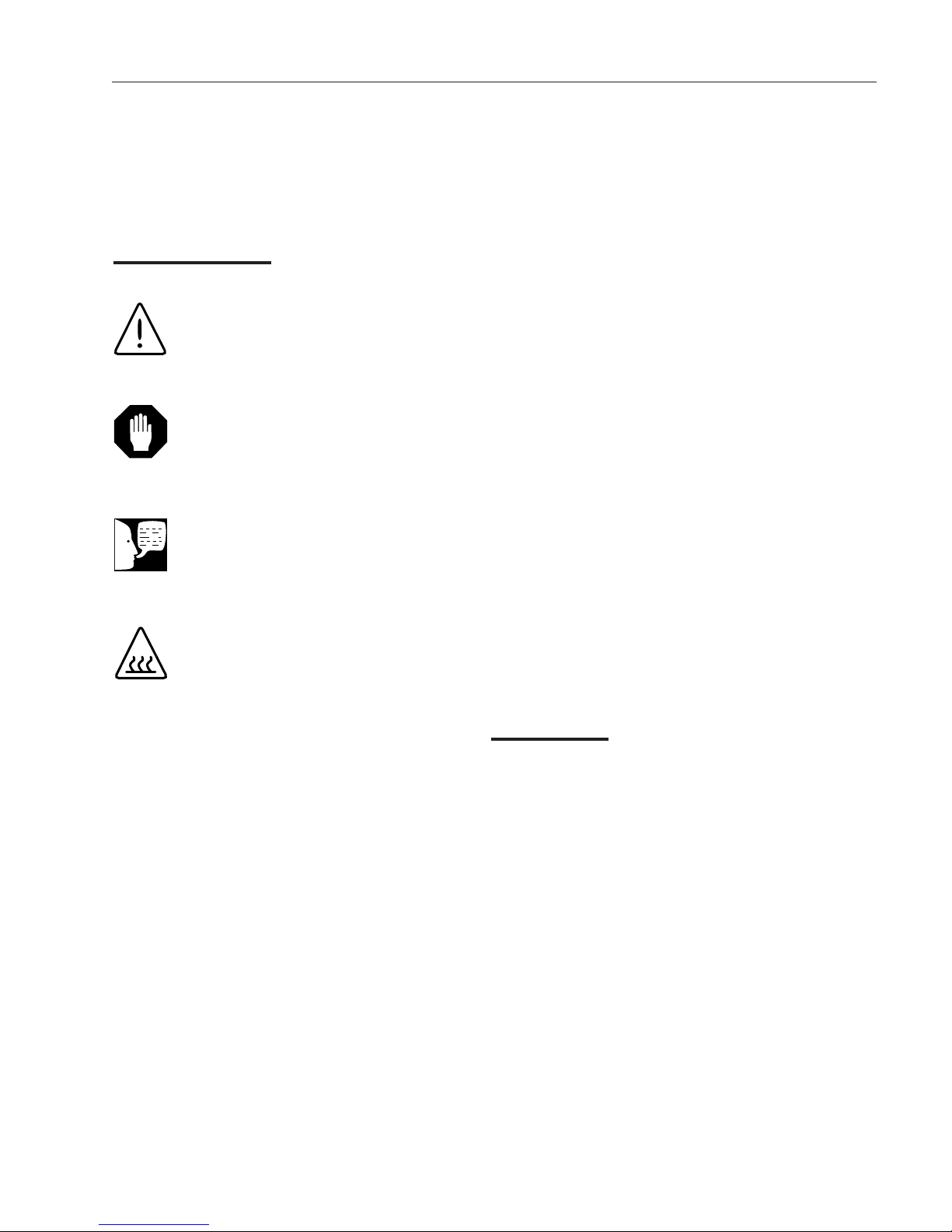
Alert Signals
Warning
Warnings alert you to a possibility of personal injury.
Caution
Cautions alert you to a possibility of
damage to the equipment.
Note
Notes alert you to pertinent facts and
conditions.
Safety Information
Your Thermo Scientific Cimarec Hot Plate has been
designed with function, reliability, and safety in mind. It
is your responsibility to install it in conformance with
local electrical codes. For safe operation, please pay
attention to the alert signals throughout the manual.
Warning: These products should be used only under
the operating conditions specified in the Operating
Manual. Always use safe laboratory practices and do
not leave the hotplate in operation while unattended as
product funcionality or laboratory practice failures could
occur that might lead to uncontrolled or excessive
heating of the top surface. Safety procedures (including, but not limited to, unplugging when not in use) and
response plans should be put in place to address the
worst case possibility. If an over-temperature failure
occurs, the top surface temperature could rise to the
maximum temperature (300-540°C depending on your
model’s specification) and remain at that temperature
indefinitely. Under these conditions, the material being
heated on the surface of the hotplate could reach levels in excess of the maximum temperature.
Hot Surface
Hot surfaces alert you to a possibility of
personal injury if you come in contact
with a surface during use or for a period
of time after use.
This manual contains important operating and safety
information. The user must carefully read and understand the contents of this manual prior to the use of
this equipment.
Warnings
To avoid electrical shock, always:
1. Use a properly grounded electrical outlet of
correct voltage and current handling capacity.
2. Disconnect from the power supply prior to
maintenance and servicing.
To avoid personal injury:
1. Do not use in the presence of flammable or
combustible materials — fire or explosion
may result. This device contains components
which may ignite such materials. Not rated
for use in hazardous atmospheres.
2. Use caution when heating volatile materials;
top surface and element can reach the “Flash
Point Temperature” of many chemicals.
These hot plates are not explosion proof. Fire
or explosion may result. Unit contains compo-
3
Page 4

SAFETY INFORMATION
nents which may ignite such materials.
3. Keep top surface clean. Use a non-abrasive
cleaner. Alkali spills, hydrofluoric acid spills or
phosphoric acid spills may damage top and lead
to thermal failure. Unplug unit and remove spills
promptly. Do not immerse unit for cleaning.
4. Replace the top immediately if damaged by
etching, scratching or chipping. A damaged top
can break in use.
5. Do not use metal foil on hot plate which may
block air flow. Overheating will result.
6. Check and tighten the removable cord periodically making sure it is secure. If loosened, the
cord could become hot and/or spark and be a
potential fire hazard. If cord appears damaged,
replace immediately. If cord is repeatedly loosened it is recommended to purchase the cord
retaining clip (part number AY1313X1 or
AY1313X2) listed in the Replacement Parts section of this manual.
7. Do not remove or modify grounded power plug.
Use only properly grounded outlets to avoid
shock hazard.
8. Use appropriate hand and eye protection when
handling hazardous chemicals.
9. Gross weight of items placed on top of hot
plates should not exceed 35 lbs. (15.9 kg.) on
the 10” x 10” models, 25 lbs. (11.3 kg) on the 7”
x 7” models, and 15 lbs. (6.8 kg.) on the 4” x 4”
models.
10. “Caution: Hot Top. Avoid Contact.” The top plate
of the unit can remain hot for some time after
use. A “CAUTION - HOT TOP” light will remain
on until top plate temperature cools to below
50°C.
11. Note that the exterior housing will be hot during
and for a period of time after use.
12. Refer servicing to qualified personnel.
4
Page 5

Specifications
4" X 4"
odel Number HP130915 HP130910-33 HP130914
M
verall Dimensions in. (cm)
Width 5.0” (12.7 cm) 5.0” (12.7 cm) 5.0” (12.7 cm)
Height 3.6" (9.7 cm) 3.6" (9.7 cm) 3.6" (9.7 cm)
Depth 10.0" (25.4 cm) 10.0" (25.4 cm) 10.0" (25.4 cm)
Weight lbs (kg) 7.0 lbs (3.2 kg) 7.0 lbs (3.2 kg) 7.0 lbs (3.2 kg)
Width 4.25" (10.8 cm) 4.25" (10.8 cm) 4.25" (10.8 cm)
Height 1.0" (2.5 cm) 1.0" (2.5 cm) 1.0" (2.5 cm)
Depth 4.25" (10.8 cm) 4.25" (10.8 cm) 4.25" (10.8 cm)
Volts 120 220-240 100
Amps 3.2 1.7 3.8
Watts 385 420 385
Freq. 60 50/60 50/60
Phase 11 1
Max. Temp. °F (°C) 1004°F (540°C) 1004°F (540°C) 1004°F (540°C)
7" X 7"
Model Number HP131225 HP131220-33 HP131224
Width 8.2” (20.8 cm) 8.2” (20.8 cm) 8.2” (20.8 cm)
Height 3.8” (9.7 cm) 3.8” (9.7 cm) 3.8” (9.7 cm)
Depth 13.0” (33.0 cm) 13.0” (33.0 cm) 13.0” (33.0 cm)
Weight lbs (kg) 11.0 lbs (5.0 kg) 11.0 lbs (5.0 kg) 11.0 lbs (5.0 kg)
Width 7.25” (18.4 cm) 7.25” (18.4 cm) 7.25” (18.4 cm)
Height 1.0" (2.5 cm) 1.0" (2.5 cm) 1.0" (2.5 cm)
Depth 7.25” (18.4 cm) 7.25” (18.4 cm) 7.25” (18.4 cm)
Volts 120 220-240 100
Amps 8.8 4.8 10.7
Watts 1060 1150 1070
Freq. 60 50/60 50/60
Phase 111
Max. Temp. °F (°C) 1004°F (540°C) 1004°F (540°C) 1004°F (540°C)
O
Top Plate
lectrical Ratings
E
Overall Dimensions in. (cm)
Top Plate
Electrical Ratings
10" X 10"
Model Number HP131535 HP131530-33 HP131534
Width 11.38” (28.9 cm) 11.38” (28.9 cm) 11.38” (28.9 cm)
Height 4.0” (10.2 cm) 4.0” (10.2 cm) 4.0” (10.2 cm)
Depth 16.25” (41.3 cm) 16.25” (41.3 cm) 16.25” (41.3 cm)
Weight lbs (kg) 13.75 lbs. (6.24 kg) 13.75 lbs. (6.24 kg) 13.75 lbs. (6.24 kg)
Width 10.5” (26.7 cm) 10.5” (26.7 cm) 10.5” (26.7 cm)
Height 1.0" (2.5 cm) 1.0" (2.5 cm) 1.0" (2.5 cm)
Depth 10.5" (26.7 cm) 10.5" (26.7 cm) 10.5" (26.7 cm)
Volts 120 220-240 100
Amps 11.7 6.4 11.2
Watts 1410 1530 1125
Freq. 60 50/60 50/60
Phase 111
Max. Temp. °F (°C) 750°F (400°C) 750°F (400°C) 750°F (400°C)
Overall Dimensions in. (cm)
Top Plate
Electrical Ratings
5
Page 6

SPECIFICATIONS
Heating Specifications
Top Plate Surface - Solid Ceramic
Temperature range
All 4" x 4" and 7" x 7" models: 41°F to 1004°F (5°C* - 540°C)
All 10" x 10" models: 41°F to 752°F (5°C - 400°C)
Heat-up time to maximum temperature (unloaded top plate). 8 minutes
Temperature stability at the center of the top plate surface (@ 100°C). ± 2.0°C
Accuracy of the temperature display vs the average actual temperature of a ± 5.0°C
2” diameter of setting area at the center of the top plate (setpoint 100°C).
(Top plate temperature was verified with an infrared camera mounted approx. 26"
above the center of the top plate surface; temperature accuracy at the edges of the
top plate may vary from the stated accuracy.)
Top Plate Size Max Recommended Flask Size Max Weight on Top Plate
4" x 4" 1 liter 15 lbs
7" x 7" 4 liters 25 lbs
10" x 10" 6 liters 35 lbs
* This hot plate does not cool. The minimum temperature is 5°C if used in a cold room.
6
Page 7

SPECIFICATIONS
Environmental Conditions
Operating: 17°C to 27°C; 20% to 80% relative
humidity, non-condensing.
Installation category II (overvoltage) in accordance
with IEC 664.
Pollution degree 2 in accordance with IEC 664.
Altitude Limit: 2,000 meters.
Storage: -25°C to 65°C
10% to 85% relative humidity
Declaration of Conformity
(for 220-240 volt, -33 CE models only)
We hereby declare under our sole responsibility that this product conforms with the technical requirements of
the following standards:
EMC: EN 61000-3-2 Limits for harmonic current emissions
EN 61000-3-3 Limits for voltage fluctuations and flicker
EN 61326-1 Electrical equipment for measurement, control, and
laboratory use; Part I: General Requirements
Safety: EN 61010-1 Safety requirements for electrical equipment for
measurement, control, and laboratory use;
Part I: General Requirements
EN 61010-2-010 Part II: Particular requirements for laboratory equipment for
the heating of materials
per the provisions of the Electromagnetic Compatibility Directive 89/336/EEC, as amended by 92/31/EEC and
93/68/EEC, and per the provisions of the Low Voltage Directive 73/23/EEC, as amended by 93/68/EEC.
The authorized representative located within the European Community is:
Thermo Fisher Scientific
419 Sutton Road
Southend On Sea
Essex SS2 5PH
United Kingdom
Copies of the Declaration of Conformity are available upon request.
7
Page 8

Introduction
Please read all the information in this manual before
operating the unit.
Your Cimarec hot plate is a general purpose heating plate
designed for laboratory procedures requiring precise control of temperature. Each Cimarec hot plate model
includes a digital display for monitoring actual temperature. The hot plate is capable of producing accurately
controlled top plate temperatures from 5°C through 540°C
on all 4" x 4" and 7" x 7" models, and the 5°C through
400°C models on the 10" x 10" models. The temperature
is controlled at the plate surface by an internal sensor.
The top plate on the Cimarec units is solid ceramic, and
is suitable for use with glass or metal vessels.
Your Cimarec hot plate may be used for general purpose
heating applications, including sample preparation, heating reagents, melting paraffin, warming resinous chemicals, content analysis, solvent evaporations, digestions,
media preparation and sterilization, titrations, sand baths,
and microscale chemistry applications.
General Usage
Do not use this product for anything other than its intended usage.
8
Page 9

Principles of Operation
Each Cimarec unit utilizes the latest in microprocessor
technology to deliver a reliable, controlled, ceramic top
hot plate.
Your Cimarec hot plate has an electronic closed-loop
feedback control which will accurately maintain temperature setpoints from 5°C through 400°C or 540°C,
depending on the model. The top plate surface temperatures are calibrated and verified at the factory using
the latest in infrared temperature measurement. The
measurements are made with an infrared camera
mounted approximately 26" above the top surface of
the hot plate. If the temperature measurement of the
ceramic top is made with measurement devices other
than infrared, the error of the measuring technique may
be greater than the error of the unit.
9
Page 10

Unpacking and Installation
Unpacking
Remove your Cimarec hot plate from the carton. Inspect
to ensure that the unit has not been damaged during
shipment. If the unit appears to have sustained shipping
damage contact the distributor from whom you purchased
this product or Customer Service at 800-553-0039.
Check for thumbscrew prior to discarding packaging.
The following items are included in the shipment:
Cimarec Hot Plate
Cord
Adapter (100V models only)
Warning
Use a properly grounded electrical
outlet of correct voltage and current
handling capacity.
Knob
Operator’s Manual
If any of these items are missing from the carton, contact
customer service.
Installation
Set the unit on a flat stable surface at least 12" away from
combustible materials, and plug the cordset into a properly grounded electrical outlet of correct voltage and current
handling capacity.
10
Page 11

Operation
Warning
Use caution when heating volatile
materials; top surface and element
can reach the “Flash Point
Temperature” of many chemicals.
These hot plates are not explosion
proof. Fire or explosion may result.
Unit contains components which may
ignite such materials.
Use appropriate hand and eye protection when handling hazardous chemicals.
“Caution: Hot Top. Avoid Contact.” The
top plate of the unit can remain hot for
some time after use. A “CAUTION HOT TOP” light will remain on until top
plate temperature cools to below
50°C.
Caution
To avoid damage to the top plate or
heating element, always keep a vessel
filled with liquid on the top plate of a
hot plate when the unit is heating or
cooling.
When plugging in the hot plate and powering it up for the
first time, you will see the software version and hertz displayed briefly on the digital display.
There is no ON/OFF button on the Cimarec hot plate.
Simply turn the HEAT knob clockwise to activate.
Setting the Temperature
Your Cimarec hot plate has an electronic closed-loop
feedback control which will accurately maintain temperature setpoints in 5° increments from 5°C through 400°C or
540°C, depending on the model. An unloaded hot plate
will heat to maximum temperature in just 8 minutes. The
temperature is controlled at the top plate by the internal
sensor. A “CAUTION - HOT TOP” light on the front panel
will illuminate whenever the top surface temperature
exceeds 50°C.
Your Cimarec hot plate will display the temperature in °C.
When choosing a setpoint, the display will indicate the
setpoint for 5 seconds, after which the display will flash
until the desired setpoint is reached.
If you want to ensure that the unit will not heat, turn the
HEAT knob counter-clockwise to OFF. The display will
alternate between HOT and OFF, and the “HOT TOP”
light will flash until the top surface has cooled to 50°C.
Nothing will be displayed on the screen when the unit has
been cooled down and the knob is turned to OFF.
To Achieve Fast Heat-up of
Large Volumes
If you are heating larger volumes, faster heating can be
achieved by turning the heat control knob to maximum
temperature until the solution starts to heat, and then
turning the setpoint back to your desired top plate temperature. The display will flash the new setpoint until that
temperature has been reached.
11
Page 12

OPERATION
Note
The solution temperature is approximately 25% cooler than the hot plate
surface temperature.
Note
If you allow the top plate to reach the
maximum temperature of 540°C while
preheating and then turn the control
down to a setpoint less than 200°C,
the temperature of the top will drop
rapidly to 200°C. Because of the natural cooling characteristics of ceramic,
the temperature of the top will drop
much more gradually after the top plate
temperature reaches 200°C.
Heating Small Volumes
Preheating small volumes is not necessary as it may
cause the temperature to overshoot the desired setpoint.
Heating Metal Vessels and
Sand Baths
Because the advanced electronic control in the
Cimarec is capable of precisely regulating the top plate
temperature, metal vessels and sand baths may be
heated safely without the danger of the ceramic top
breaking. Use the lowest temperature setting possible
for applications to limit thermal stress to the ceramic
top. Using a metal vessel or sand bath may reduce
the life of the hot plate.
12
Note
Boiling times are dependent on solution volume and the surface area of the
flask that is exposed to the hot plate.
For example, when heating the same
amount of solution in a 2L flask vs. a
1L flask, the solution will heat about
20% faster.
Page 13

Maintenance
General Cleaning Instructions
Wipe exterior surfaces with lightly dampened cloth containing mild soap solution.
13
Page 14

Troubleshooting
Error Codes
The following errors should not be addressed by the user. If any of the errors appear, contact Technical
Service at 800-553-0039.
Displayed Message Intended to Detect Cause Solution
E01 Thermocouple Thermocouple not connected. Replace element
Call Tech. Service out of range. assembly (attached to
thermocouple).
Thermocouple open circuit.
E02 Excessive heat-up time. Thermocouple short circuit. Remove short.
Call Tech. Service
Failure of element. Replace element
assembly (attached to
thermocouple).
Failure of element circuit. Replace Element.
Replace Control Board.
14
Page 15

Exploded Views
5
6
7
1
2
220-240V
Models Only
9
8
9
11
Optional
Accessory
Ref. "A"
10
12
4
3
4x4 Exploded View
15
Page 16

EXPLODED VIEWS
13
15
(Note routing of
leads and thermocouple)
16
Number located
this side.
17
14
4x4 Exploded View - Top Plate
16
Page 17

EXPLODED VIEWS
4
5
6
7
1
2
220-240V
Models Only
8
9
Optional
Accessory
Ref. "A"
10
3
12
11
7x7 Exploded View
17
Page 18

EXPLODED VIEWS
13
15
(Note routing of
leads and thermocouple)
16
Number located
this side.
17
14
7x7 Exploded View - Top Plate
18
Page 19

4
3
5
6
7
1
2
220-240V
Models Only
8
9
11
Optional
Accessory
Ref. "A"
10
12
EXPLODED VIEWS
10x10 Exploded View
19
Page 20

13
15
(Note routing of
leads and thermocouple)
16
Number located
this side.
17
10x10 Exploded View - Top Plate
20
Page 21

Wiring Diagram
21
21
Page 22

Replacement Parts
Key 4x4 Part No. 7x7 Part No. 10x10 Part No. Description
1 261575 261575 261575 PC Board Fuse - 220-240V
2 FTX34 FTX34 FTX34 Foot (4)
3 PC1312X1 PC1312X1 PC1315X1 Control Board - 100V, 120V
3 PC1312X2 PC1312X2 PC1315X2 Control Board - 220-240V
4 266058 266058 266058 PC Board Fuse 100V, 120V
5 PC1313X2 PC1313X2 PC1313X2 Display Board
6 PC1313X1 PC1313X1 PC1313X1 Speed/Heat Adjustment Board (2)
7 DLX277 DLX280 DLX283 Dial Plate
8 KBX103 KBX103 KBX104 Knob (2)
9 CEX373 CEX373 CEX373 Power Entry Module
10 CRX106 CRX106 CRX106 Cord Set - 100 V, 120V
10 CRX107 CRX107 CRX107 Cord Set - 220-240V
11 KBX78 KBX78 KBX78 Knob
12 AY1313X1 AY1313X1 AY1313X1 Retaining Clip - 100V, 120V
12 AY1313X2 AY1313X2 AY1313X2 Retaining Clip - 220-240V
13 JNX33 JNX35 -- Lower Insulation
14 JNX34 JNX36 JNX38 Upper Insulation
15 ELX41 ELX44 ELX47 Heating Element - 120V - w/thermocouple
15 ELX42 ELX45 ELX48 Heating Element - 100V - w/thermocouple
15 ELX43 ELX46 ELX49 Heating Element - 220-240V - w/thermocouple
16 540-0033 710-0117 719-0073 Ceramic Top
17 EL1310X1 EL1313X1 EL1316X1 Hot Plate Top Assembly - 120V
17 EL1310X2 EL1313X2 EL1316X2 Hot Plate Top Assembly - 100V
17 EL1310X3 EL1313X3 EL1316X3 Hot Plate Top Assembly - 220-240V
Accessories
Part No. Description
711S Non-Mercury Thermometer 20 to 100°C Range
647-1S Non-Mercury Thermometer 0 to 110°C Range
1007-3BLS Non-Mercury Thermometer -1 to 201°C Range
7077 Thermometer Clamp
7068 90° Clamp Holder
1000-2 12” Aluminum Rod
7078 Large Clamp
7079 Small Clamp (up to 1/2”)
22
Page 23

Ordering Procedures
Please refer to the Specification Plate for the complete
model number, serial number, and series number when
requesting service, replacement parts or in any correspondence concerning this unit.
All parts listed herein may be ordered from the Thermo
Scientific dealer from whom you purchased this unit or
can be obtained promptly from the factory. When service
or replacement parts are needed we ask that you check
first with your dealer. If the dealer cannot handle your
request, then contact our Customer Service Department
at 563-556-2241 or 800-553-0039.
Prior to returning any materials, please contact our
Customer Service Department for a “Return Materials
Authorization” number (RMA). Material returned without
an RMA number will be refused.
23
Page 24

Two Year Limited Warranty
This Thermo Scientific product is warranted to be free of defects in materials and workmanship for two (2)
years from the first to occur of (i) the date the product is sold by the manufacturer or (ii) the date the product is
purchased by the original retail customer (the “Commencement Date”). Except as expressly stated above, the
MANUFACTURER MAKES NO OTHER WARRANTY, EXPRESSED OR IMPLIED, WITH RESPECT TO THE
PRODUCTS AND EXPRESSLY DISCLAIMS ANY AND ALL WARRANTIES, INCLUDING BUT NOT LIMITED
TO, WARRANTIES OF DESIGN, MERCHANT ABILITY AND FITNESS FOR A PARTICULAR PURPOSE.
An authorized representative of the manufacturer must perform all warranty inspections. In the event of a
defect covered by the warranty, we shall, as our sole obligation and exclusive remedy, provide free replacement parts to remedy the defective product. In addition, for products sold within the continental United States
or Canada, the manufacturer shall provide free labor to repair the products with the replacement parts, but
only for a period of ninety (90) days from the Commencement Date.
The warranty provided hereunder shall be null and void and without further force or effect if there is any (i)
repair made to the product by a party other than the manufacturer or its duly authorized service representative, (ii) misuse (including use inconsistent with written operating instructions for the product), mishandling,
contamination, overheating, modification or alteration of the product by any customer or third party or (iii) use
of replacement parts that are obtained from a party who is not an authorized dealer of Thermo Scientific products.
Heating elements, because of their susceptibility to overheating and contamination, must be returned to the
factory and if, upon inspection, it is concluded that failure is due to factors other than excessive high temperature or contamination, the manufacturer will provide warranty replacement. As a condition to the return of any
product, or any constituent part thereof, to the factory, it shall be sent prepaid and a prior written authorization
from the manufacturer assigning a Return Materials Number to the product or part shall be obtained.
IN NO EVENT SHALL THE MANUFACTURER BE LIABLE TO ANY PARTY FOR ANY DIRECT, INDIRECT,
SPECIAL, INCIDENTAL, OR CONSEQUENTIAL DAMAGES, OR FOR ANY DAMAGES RESULTING FROM
LOSS OF USE OR PROFITS, ANTICIPATED OR OTHERWISE, ARISING OUT OF OR IN CONNECTION
WITH THE SALE, USE OR PERFORMANCE OF ANY PRODUCTS, WHETHER SUCH CLAIM IS BASED ON
CONTRACT, TORT (INCLUDING NEGLIGENCE), ANY THEORY OF STRICT LIABILITY OR REGULATORY
ACTION.
For the name of the authorized Thermo Scientific product dealer nearest you or any additional information, contact us:
2555 Kerper Blvd., Dubuque, Iowa, 52004-0797
Phone: 563-556-2241 or 1-800-553-0039
Fax: 563-589-0516
Web: www.thermo.com
24
 Loading...