

Thermo Scientific Sarasota 200, HB-S200 User Manual
Sarasota 200
Ultrasonic Multipath Flowmeter
User Guide
P/N HB-S200
Revision A
Part of Thermo Fisher Scientific


Sarasota 200
Ultrasonic Multipath Flowmeter
User Guide
P/N HB-S200
Revision A


©2007 Thermo Fisher Scientific Inc. All rights reserved.
All trademarks are the property of Thermo Fisher Scientific Inc. and its subsidiaries.
Thermo Fisher Scientific (Thermo Fisher) makes every effort to ensure the accuracy and completeness of
this manual. However, we cannot be responsible for errors, omissions, or any loss of data as the result of
errors or omissions. Thermo Fisher reserves the right to make changes to the manual or improvements to
the product at any time without notice.
The material in this manual is proprietary and cannot be reproduced in any form without expressed
written consent from Thermo Fisher.
Thermo Fisher Scientific
1410 Gillingham Lane
Sugar Land, TX 77478
USA
Phone: 713-272-0404
Fax: 713-272-2272
Web: www.thermofisher.com
Thermo Fisher Scientific
14 Gormley Industrial Avenue
Gormley, Ontario L0H 1G0
Canada
Phone: 905-888-8808
Fax: 905-888-8828

This page intentionally left blank.

Sarasota 200 Ultrasonic Multipath Flowmeter
SECTION 1
INTRODUCTION
1.2.1 The Standard
1.3 Implementation of principles in Sarasota 200
1.1 Applications
1.2 Principle of operation
1.2.2 Velocity x area method
1.2.3 Water level
1.2.4 Water velocity
1.2.5 Flow determination
1.2.5.1 Mid section method
1.2.5.2 Mean section method
1.2.6 Path configurations
1.2.7 Transducer frequency
1.2.8 Minimum depth of water
1.2.9 Performance estimates
INDEX
SECTION 2
SYSTEM COMPONENTS
2.1 Flowmeter system overview
2.2 Family tree
2.3 Flowmeter contents and options
2.3.1 Flowmeter layout
2.3.2 Internal components
2.3.2.1 Mother board
2.3.2.1.1 Power supply & internal battery
2.3.2.1.2 Transducer connections
2.3.2.1.3 Depth input signals
2.3.2.1.4 Output signal connections
2.3.2.1.5 Relay connections
2.3.2.1.6 Digital signal connections
2.3.2.1.7 Serial communications
2.3.2.2 Central processor (CPU)
2.3.2.3 LCD display
2.3.2.4 Transducer interface card (TIF)
2.3.2.5 AC power adapter
2.4 Ultrasonic transducers
2.4.1 1 MHz transducers
2.4.2 1 MHz I.S. transducers
2.4.3 500 kHz transducers
2.4.4 Lower frequency transducers
2.4.5 Maximum cable lengths
2.5 Controls and displays
2.6 Software & firmware
2.6.1 Operating firmware
2.6.2 “GAFA” PC software
2.7 Documentation
INDEX Page 1
Thermo Fisher Scientific

Sarasota 200 Ultrasonic Multipath Flowmeter
SECTION 3
PERIPHERAL EQUIPMENT
SECTION 4
INSTALLATION
4.1 Safety
SECTION 5
COMMISSIONING
5.1 Site dimensions
SECTION 6
CALIBRATION/
VERIFICATION
3.1 Additional items
3.2 Transducer mounting hardware
4.2 General
4.3 Unpacking and laying out
4.4 Installing transducer assemblies
4.5 Connecting transducers to flowmeter
4.6 Transducer alignment
4.7 Output connections
4.8 Power connection
5.2 Powering up
5.3 Programming
5.4 Setting up
5.5 Outputs
6 Calibration/verification
INDEX
SECTION 7
MAINTENANCE
7.1 Channel maintenance
7.1.1 Weed
7.1.2 Profile
7.1.3 Debris
7.2 Flowmeter maintenance
7.3 Routine checks
7.3.1 Remote
7.3.2 On site
APPENDIX 1
GAFA PC SOFTWARE
A2 GAFA PC software
INDEX Page 2
Thermo Fisher Scientific

Sarasota 200 Ultrasonic Multipath Flowmeter
APPENDIX 2
SPECIFICATION
A2.1 Enclosure
A2.2.1 DC supply
A2.3 Electronics
A2.4.1 1 MHz
A2.5 GAFA software
A2.2 Power supply
A2.2.2 AC power adap ter modu le
A2.3.3 Internal battery option
A2.4 Transducers
A2.4.2 500 kHz
A2.4.3 Other frequencies
A2.4.4 Transducer ca ble
INDEX
APPENDIX 3
REFERENC ES
A3 References
APPENDIX 4
SITE DATA BOOK
A4.1 Model and serial number
A4.2 Site and customer
A4.3 General description
A4.4 Software issue
A4.5 Card layout in rack
A4.6 Programmed data
A4.7 Schedule of drawings
A4.8 Test certificates
APPENDIX 5
I.S. INTERFACE AND
TRANSDUCER
A5.1 Introduction
A5.2 Installation Guidelines
A5.3 Marking
A5.4 Maintenance
INDEX Page 3
Thermo Fisher Scientific

Sarasota 200 Ultrasonic Multipath Flowmeter
This page is blank
INDEX
INDEX Page 4
Thermo Fisher Scientific
Sarasota 200 Ultrasonic Multipath
Flowmeter
INTRODUCTION
1 INTRODUCTION
1.1 Applications
The Thermo Scientific Sarasota 200 is a velocity x area open channel flowmeter which uses
the ultrason ic “ tim e of fli ght ”, also kno wn as th e “tr ans it t ime” m et hod. It is sim ilar to the l arge r
Sarasota 2000 but with fewer ultrasonic velocity paths (up to 4) and just one water channel.
Unlike traditional methods of open channel flow measurement which use weirs or flumes, the
transit time method creates no obstruction and assumes no relation between level and flow. It
will correctly determine flow throughout its designed range by measuring water velocity and
cross section area (see Section 1.2).
The method is tolerant of backwater effects caused by tides, downstream confluence or
blockages. Unlike a weir or flume it does not drown out at high flow conditions.
The method employs the transmission of ultrasonic “beams” which can be affected by factors
which impede or deflect them. For this reason the method should not be used in situations of:
• Aerated water
• Weed growth between the transducers (unless it is regularly cut)
• High levels of suspended solids (greater than 2000 mg/l) *
• Gradients
• Gradients
* In relatively small channels (up to 5 metres) the method is more tolerant of
** Provided the velocity of sound in water (VOS) remains within the range 1350 to 1650
Though described as an open channel method, the flowmeter may be used in closed
conduits, including those which run full. In the latter case, the cross section area is defined by
the conduit geometry without the need to measure water level.
Suitable applications include water flow measurement of:
• Rivers
• Canals
• Aqueducts
• Irrigation conduits
• Sewage discharges
• Sewage works
• Industrial discharges
• Power generation
Note that although the flowmeter is most often used for open channels or part filled conduits,
it is often used for conduits which always run full. Under these circumstances it is not
necessary to have a depth input but steps need to be taken to ensure that the flowmeter
always takes the conduit as full. This is done via the fixed level input PC screen. The conduit
shape must sti ll be ent e red.
of salinity (the actual value of salinity is, however, unimportant**)
of temperature (the actual temperature is, however, unimportant**)
suspended solids and therefore is often used in sewage applications.
m/s
Section 1 INTRODUCTION Page 1-1
Thermo Fisher Scientific

Sarasota 200 Ultrasonic Multipath
Flowmeter
1.2 Principle of operation
1.2.1 The Standard
The Thermo Scie ntific Sarasota 200 is an ultrasonic “tra nsit time” flowmet er which complies
with the International Standard ISO 6416. The UK standard BS 3680 part 3E is identical. The
transit time method belongs to the general category of velocity x area methods. A full
description of the method and its applications is to be found in the Standard. A brief summary
is given below.
1.2.2 Velocity x area method
Velocity x area methods require a means of determining the water velocity and the cross
section area. The product of the two determines the flow rate in a manner which is not
dependent on factors influencing the level, for example downstream constrictions, tidally
affected water level etc.
Assuming the shape of the channel cross section is stable, determination of the area
becomes a matter of measuring water level. This may be done by a variety of methods.
1.2.3 Water level
Water level is required in order to determine the cross section area in an open channel.
Though a single level measurement may be used, it is common to use more than one and to
average them. This has the advantage of a more representative level, particularly if the
measurements are made at different positions, for example on either side of the channel.
Another advantage is that flow may still be computed even if a level sensor fails.
Level may be determined by using one or more ultrasonic transducers in the water facing
upwards. The time taken for a pulse of sound to return to the transducer after being reflected
from the surface is converted into level using the velocity of sound in water as measured by
the water velocity paths (see Section 1.2.4). There is a minimum depth of water required
above the transducer for it to carry out a measurement. This is given in Appendix 2:
Specification.
Water level may also be provided by external auxiliary depth gauges via 4-20 mA signals, for
example pressure transmitters, downward facing ultrasonic devices and float systems with
shaft encoders.
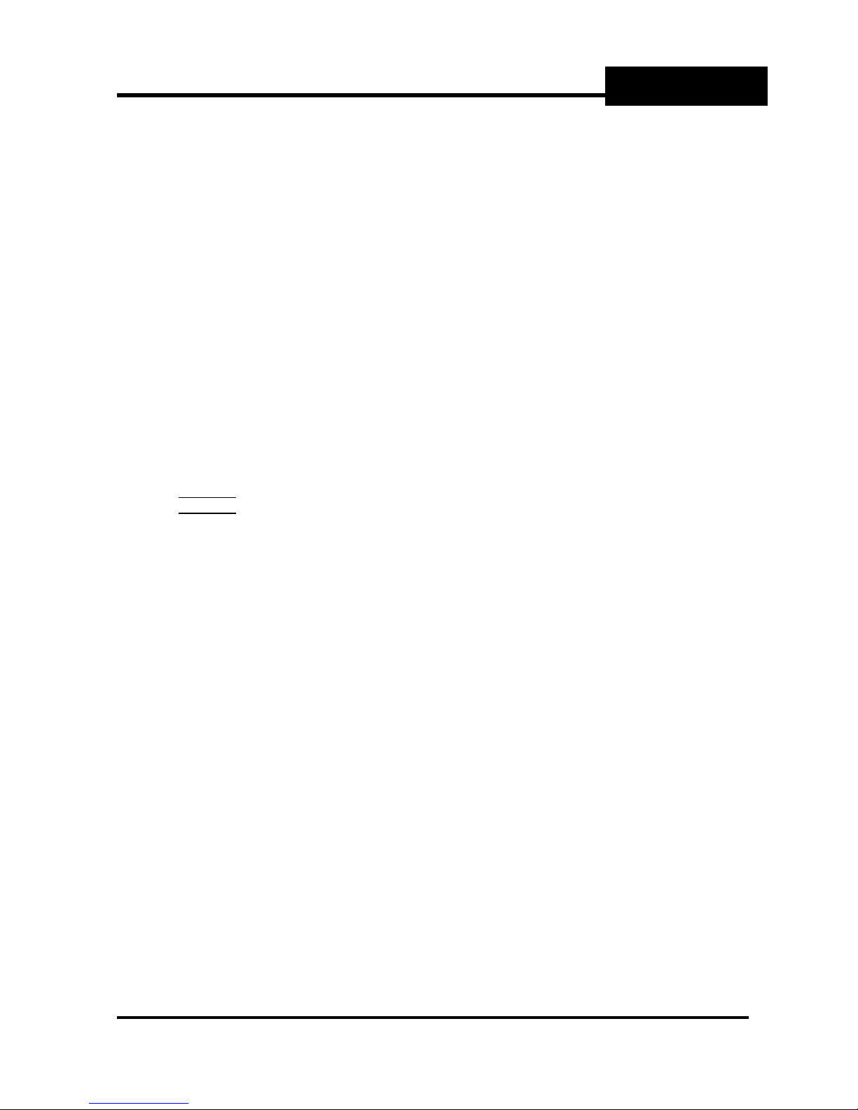
1.2.4 Water velocity
In the transit time method, water velocity is determined at a number of heights within the body
of water by measurement of time taken for pulses of ultrasound to travel across the channel
at an angle to the flow direction.
Transducers are mounted in the water at or near the sides of the channel with each pair
usually at the same height and aligned so that each one can transmit a “beam” of ultrasound
towards its partner. The ultrasonic “path” between the transducer pairs must be at an angle
(usually about 45
Each transducer acts as a transmitter and receiver and is connected to a processing unit,
which measures the transit time and the time difference.
o
) to the flow direction.
INTRODUCTION
Section 1 INTRODUCTION Page 1-2
Thermo Fisher Scientific
Sarasota 200 Ultrasonic Multipath
θ
Flowmeter
The mean water velocity at the height of each path is determined from these timing
measurements, based on pre-determined geometrical measurements (length of the path and
the angle to the flow direction).
V
It may be shown that the water velocity at the height of the path AB is:
v = L x (T
– TBA) / (TAB x TBA x 2 cosθ)
AB
Where
T
T
= Transit time from transducer A to B
AB
= Transit time from transducer B to A
BA
L = Path length (distance between transducer A and transducer B)
θ = the angle between the “path” and the direction of flow.
1.2.5 Flow determination
The flow is determined by combining the water velocity measurements at the height of each
path with the cross section area defined by the water level and the shape of the channel. The
channel shape need not be the same as the projected width between the transducers. For
example if the transducers are mounted on piles inset from the channel sides. For the
purposes of flow determination the cross section area is divided into horizontal slices
determined by the channel bed, the heights of the paths themselves and the water surface
level.
The channel flow is the sum of the flows in each slice determined by the path velocity or
velocities and the area of the slice. The bottom slice is defined by the bed (which is assumed
not to move) and the top slice by the water surface (the level of which is me asured by the
flowmeter). The slice widths may be determined by the projected width between the
transducers or by a separate table defining the cross section shape. The latter method is
used by the Sarasota 200.
There are 2 methods, mid section and mean section.
Transducer A
Direction of the Flow
Ultrasonic Path
Transducer B
INTRODUCTION
Section 1 INTRODUCTION Page 1-3
Thermo Fisher Scientific
Sarasota 200 Ultrasonic Multipath
Flowmeter
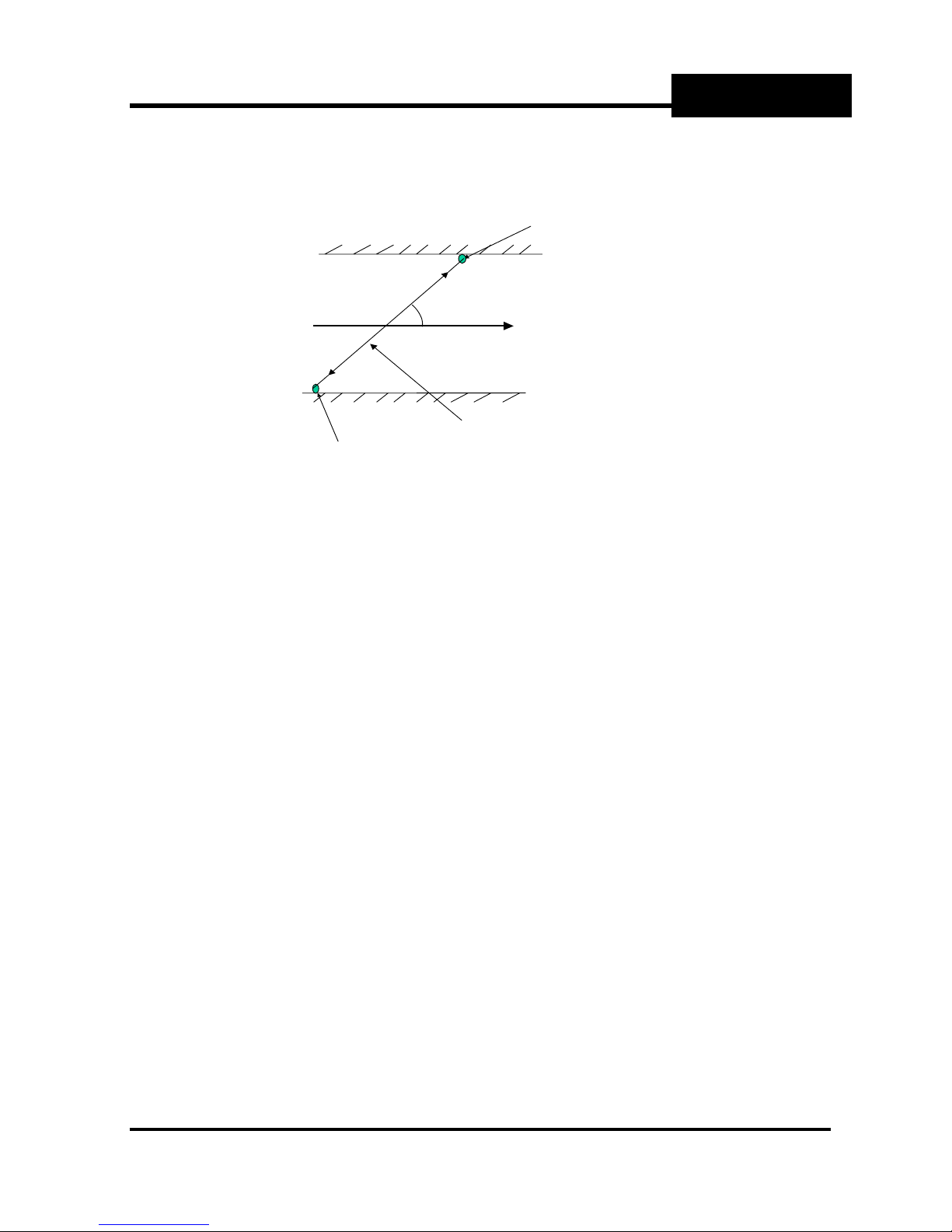
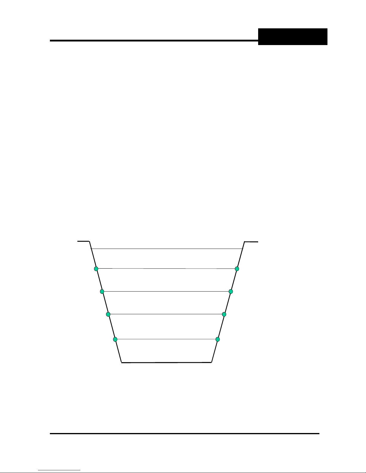
1.2.5.1 Mid section method
In the mid section method, the slice boundaries are defined by lines mid way between the
paths. The slice velocity is taken as that determined by the ultrasonic path within the slice and
the slice area as the product of the slice height and the (average) width. The upper boundary
of the top slice is the water surface. At the bottom, an additional slice is defined between the
bed and a line half way between the bed and the bottom path. This bottom slice has a
weighting factor, K, normally between 0.4 and 0.8 to allow for the slow moving water near the
bed. To reduce the uncertainty of this factor, the bottom path should be positioned as close to
the bed as practical.
INTRODUCTION
Height H
Top panel
½(H
+ H3)
4
S
Water S u rf ac e
QS = V4 {HS − ½(H4 + H3)}W
QS = ½V3 (H4 – H2)W
3
4
½(H3 + H2)
+ H1)
½(H
2
+ H0)
½(H
1
Height H
0
Bottom panel
QS = ½V2 (H3 – H1)W
QS = ½V1 (H2 – H0)W
QS = ½kV1 (H1 – H0)W
2
1
Width W
Bed
Width W
Illustration of the mid section method for 4 paths
Width W
Width W
Width W
1
Bed
4
3
2
Path 4 H e ight H
Path 3 Height H
Path 2 Height H
Path 1 Height H
Bed Height H
4
3
2
1
0
Section 1 INTRODUCTION Page 1-4
Thermo Fisher Scientific
Sarasota 200 Ultrasonic Multipath
4
Flowmeter
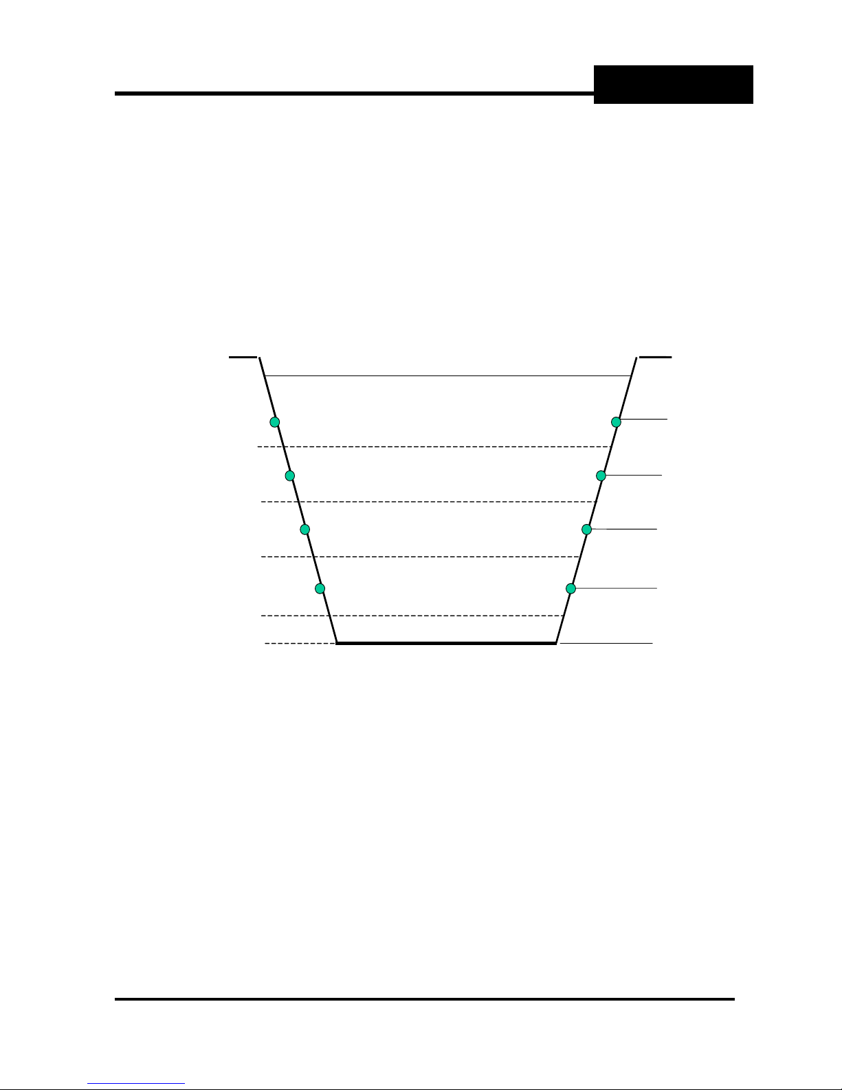
1.2.5.2 Mean section method
In the mean section method, the slice boundaries are defined by the path heights themselves.
The slice velocity is taken as the mean of the upper and lower paths which define the slice
boundaries. The upper boundary of the top slice is the water surface.
The velocit y of the water surface, Vs, is given by:-
Vs = V
Where Ks is a multiplying factor normally between 0 and 1 to allow for the projection
of velocity to the water surface
Vs is limited to a value of V
The lower boundary of the bottom slice is the bed. This bottom slice has a weighting factor,
, normally between 0.4 and 0.8 to allow for the slow moving water near the bed.
K
B
The mean section method is superior in cases where the paths are not near the slice centres,
but the mid section method handles the top slice better. The more paths that are deployed,
the less the differences matter.
The mean section method is illustrated in the following diagram:
+ (V4-V3) x Ks(Hs-H4)/(H4-H3)
4
+ (V4-V3) in the event of (Hs-H4) being greater than (H4-H3)
4
INTRODUCTION
Water Surface
Qs = ½(VS + V4) x (HS – H4) x ½(WS+ W4)
Q
= ½ (V4+ V3) x (H4 – H3) x ½(W4 + W3)
s
= ½ (V3 + V2) x (H3 – H2) x ½(W3 + W2)
Q
s
= ½ (V2 + V1) x (H2 – H1) x ½(W2 + W1)
Q
s
Q
= ½V1(1 + kB) x (H1 – H0) x ½(W1 + W
s
W
W
W
W
Wbed
Width W
4
3
2
1
)
Bed
S
Illustration of the mean section method for 4 paths
Surface Heigh t H
Path 4. Height H
Path 3. H eight H
Path 2. He i ght H
Path 1 Height H
Bed, Height H
S
3
2
1
0
Section 1 INTRODUCTION Page 1-5
Thermo Fisher Scientific

Sarasota 200 Ultrasonic Multipath
Flowmeter
1.2.6 Path configurations
The simplest arrangement is to have a number of paths “in line” above each other. This
would be suitable for a channel of regular cross section shape, which is straight for a long
distance compared with its width (5 to 10 times).
Other configurations are often used in other circumstances. For example:
• Crossed paths where there is uncertainty about the flow direction
• Sloping paths where the depth is greater on one side compared with the other
• Transducers inset from the banks
• Reflected paths where transducers are on one side only and reflectors “bounce” the
sound pulses back from the far side. This method saves cable but increases path lengths
and is very sensitive to misalignment.
The Sarasota 200 f l o wm e t e r is capable of being con f i gured for these and ot her situation s .
For more complex configurations requiring more than 4 paths or compound channels, the
Sarasota 2000 offers more flexibility. Examples are:
• Multiple sets of paths for compound channel shapes
• V configuration used to divide the width because of size or uneven profile
• Multiple channels
Please consult Thermo Fisher Scientific for examples and advice.
1.2.7 Transducer frequency
Transducers are manufactured with characteristic frequencies. These are in the range 1 MHz
to 250 kHz. For propagation reasons, the greater the path lengths the lower the frequency
and the larger the transducer. As a guide, path lengths below 10 metres would use 1MHz
transducers, 5 to 80 metres 500 kHz, 50 to 200 metres 250 kHz. These figures are for
guidance and the selection may be influenced by other factors relating to the application.
Where there is overlap, lower frequency transducers may be used to improve pen etration in
conditions of high suspended solids provided there is sufficient depth and velocity.
Please consult Thermo Fisher Scientific for advice.
1.2.8 Minimum depth of water
In order to avoid reflections from the bed or surface causing distortion of the ultrasonic
signals, a minimum height of water is necessary above each path. This depends on the
transducer frequency and the path length.
INTRODUCTION
H
= 27 √ ( L / ƒ )
min
Where:
is the minimum height of water above the path, in metres
H
min
L is the path length, in metres
ƒ is the transducer freque ncy, in Hertz
A similar restriction applies to the channel bed, particularly if it is smooth and reflects rather
than absorbs an acoustic signal. The minimum depth of water is therefore usually 2 x H
Section 1 INTRODUCTION Page 1-6
min
Thermo Fisher Scientific

Sarasota 200 Ultrasonic Multipath
Flowmeter
1.2.9 Performance estimates
ISO 6416 describes how to estimate the uncertainty of measurement in any particular
installation. Please consult Thermo Fisher Scientific for advice on this.
1.3 Implementation of the principles of operation in the Sarasota 200
The principles described in Section 1.2 are used by the Sarasota 200 subject to certain rules
as listed below. See also Appendix 1: GAFA Screens that describe in detail how the
flowmeter is programmed via a PC.
Flow
• There is a choice of mean or mid section method of flow calculation.
• The channel cross section shape is entered as a height/width table independent from the
path lengths and angles. (For rectangular or trapezoidal channels it is only necessary to
enter 2 points to define the channel.) The separate table allows the path velocities to be
applied to more accurate slice areas since the defined shape is used rather than a fixed
width for each slice as specified in the Standard.
• Where no path velocity is available, for example at low water height, flow may be inferred
from water level. This is done via a flow estimation table, which may be derived
empiricall y o r by calculation.
Velocity
• The upstream velocity transducers are connected as shown in section 2.
• Path numbering is from the bottom.
• Paths are automatically brought into operation according to the water level and the
programmed minimum water cover.
• Paths entered as being at the same height are taken as crossed, otherwise they are
separate.
• Separate paths may be “normal” with transducers on each side or “reflected” with
transducers on one side only. The latter method saves cable but is not recommended
because of the increased path lengths and sensitivity to alignment.
• The velocities calculated by a pair of paths comprising a crossed path are averaged and
the average velocity used for the slice. The velocity calculated by a separate path is used
alone for the slice.
• When a velocity path fails, the slice boundaries automatically adjust to use only the
working paths.
• A failed path will show on the status indicated. The path status is a percentage of the
“instantaneous” transducer firings which result in successful reception. If this figure drops
below 12% the path is considered to have failed during the corresponding instantaneous
cycle time and is discarded for that cycle. This could be the result of a fault, misalignment
or obstruction.
• Only valid velocity paths which are in the water and covered by sufficient water to be
operating are used for the status indication.
• Each path may have a multiplying factor (“X Factor”) assigned to it. This will normally be 1
but may be different in exceptional circumstances for calibration purposes. An example of
when this might be is when the transduce rs are not exactly at the channel edges.
• Transducers in each velocity path may be set to operate simultaneously (the norm) or
sequentially. Simultaneous operation allows more measurements in a given time but
there is a small possibility of confusing a signal reflected back to the firing transducer with
one received from the opposite transducer.
INTRODUCTION
Section 1 INTRODUCTION Page 1-7
Thermo Fisher Scientific

Sarasota 200 Ultrasonic Multipath
Flowmeter
Water level
• Levels are combined in the following algorithm:
Only non-faulty measurements are used.
Highest and/or lowest are discarded until 3 remain.
The one furthest from the others is discarded leaving 2.
The remaining 2 measurements are averaged for arbitrated level if within an
acceptable band defined via the PC GAFA software.
If they are not within the acceptable band, level determination fails and flow cannot
be calculated.
If only 1 level measurement is installed or only 1 remains after arbitration, it is used
as the arbitrated level.
If not OK, level fails and flow cannot be calculated.
• Levels defined as valid but rejected by the algorithm will be indicated on the level status.
• Where the flowmeter is installed in a cl osed conduit which always runs full, th e channel
shape is entered in the usual way but there is no need for a level measurement. The
flowmeter is programmed with a fixed level input corresponding to the top of the conduit.
Transducer and bed levels
All heights may be set to a fixed datum (local or national) or relative to mean bed level. The
former requires a height for the bed and avoids re-entering all path and level transducer
heights in the event of a change to the bed.
General
• “Instantaneous” means the average over the cycle time scale. This defaults to 10
seconds for fast response suitable for small channels. It may be set to 1 minute for
smoother averaging where the rate of change of flow conditions is slower.
• The average period is the time over which measurements are averaged for the purpose
of output or logged data. The average period cannot be shorter than the cycle time.
• At the data logging intervals, the averaged values of the selected data are stored.
• Analogue inputs will normally be linear. However, non linear characteristics may be
entered via the PC, see Appendix 1
• When operating on a 12 volt source, for example from a solar panel, power saving is
possible by using intermittent operation. Power consumption in normal and intermittent
modes is quoted in the Appendix 2: Specification.
INTRODUCTION
Section 1 INTRODUCTION Page 1-8
Thermo Fisher Scientific

Sarasota 200 Ultrasonic Multipath
Flowmeter
SYSTEM COMPONENTS
2 SYSTEM COMPONENTS
2.1 Flowmeter system overview
• The Thermo Scientific Sarasota 200 is an ultrasonic multi-path flowmeter, which complies
with ISO6416.
• It employs state of the art technology to achieve excellent performance in conditions
which have previously be en outside th e scope of this type of instrument.
• Smart transducer technology incorporating drive and receiver circuits optimises signal to
noise ratio and minimises losses. The smart circuits are located inside the transducer
housings except for the 1 MHz transducers. In that case they are in sealed in-line
housings known as Tboxes.
• Automatic adjustment of receiver gain and transducer drive voltage (HT).
• Low power consumption and intermittent modes make mains free operation feasible.
• Multi-path operation, (up to 4) with multi-drop facility made possible by smart transducer
addressing to save cable.
• Multiple water level inputs, subject to a maximum of 4 overall:
- up to 4 ultrasonic level transducers
- up to 2 auxiliary level gauges (via 4-20 mA inputs.)
• Up to 2 analogue 4-20 mA outputs
• System fault relay (volt free contacts)
• 2 programmable relays, 1 volt free contact, 1 high speed solid state. Programmable, f or
example for alarms, status, totaliser pulses.
• Two serial ports. RS232 for PC, RS232 for modem.
• Internal data logger, 1 Mbyte capacity, programmable.
• Water temper ature measurem e nt at each smart transducer (except 1 MHz transduc er s )
Section 2, SYSTEM COMPONENTS, Page 2-1
Thermo Fisher Scientific
Sarasota 200 Ultrasonic Multipath
Flowmeter
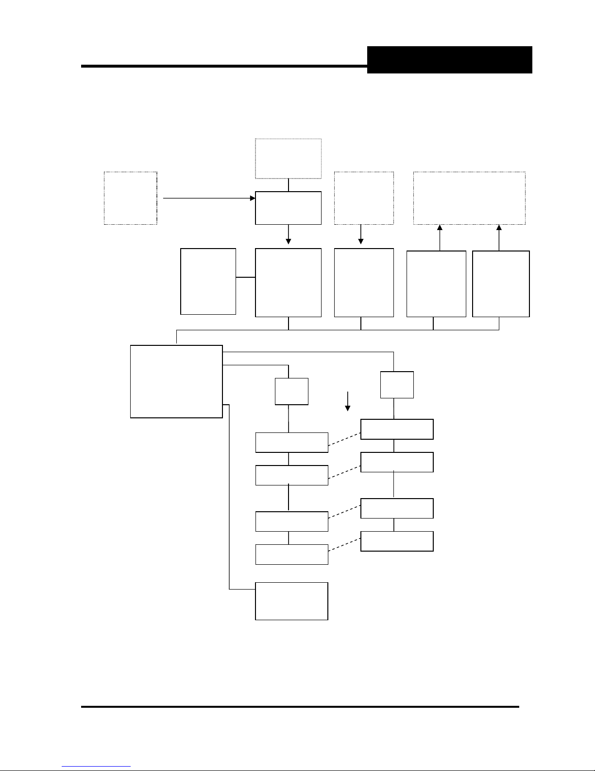
2.2 Family tree
The schematic diagram below is an illustration of a four path system.
Internal
Battery
option
External
power
source
11 to 30 V DC
Auxiliary
depths
Power
control
SYSTEM COMPONENTS
External equipment
Display
Transducer u/s
interface d/s
Level
Central
Processor
inc.
2 x serial I/O
Star
J box
Trans. 1 d/s
Trans. 2 d/s
Trans. 3 d/s
Trans. 4 d/s
Inputs
2 x
4-20 mA,
Flow
Star
J box
Trans. 1 u/s
Trans. 2 u/s
Trans. 3 u/s
Trans. 4 u/s
Outputs
2 x
4-20 mA,
Relays
2 x VFC
Section 2, SYSTEM COMPONENTS, Page 2-2
Level
Transducer
Option
Thermo Fisher Scientific
Sarasota 200 Ultrasonic Multipath
Flowmeter
2.3 Flowmeter contents and options
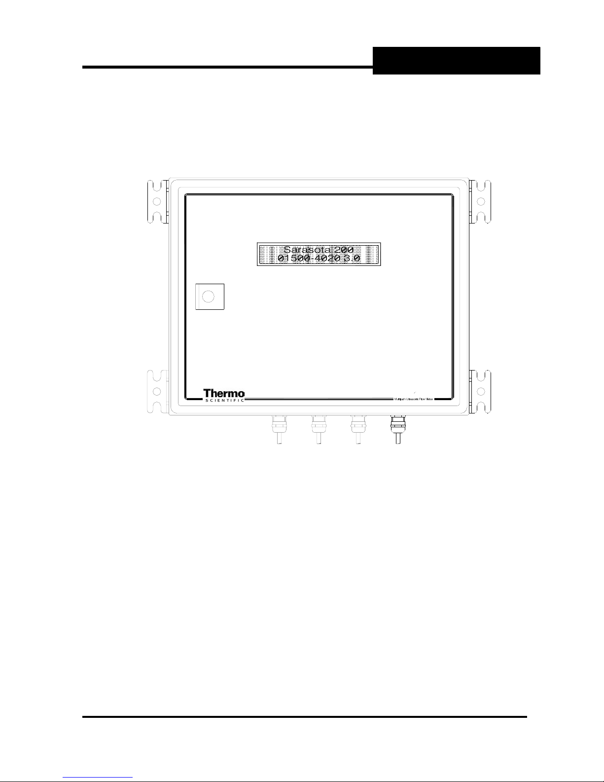
2.3.1 Flowmeter layout
SYSTEM COMPONENTS
s„˜„™•š„@RPP
Fig 1 Sarasota 200 Flowmeter. Front panel view
This view of the Sarasota 200 shows:
• the LCD display (see section 2.3.2.3)
• the cable entry glands at the bottom
• the wall mounting brackets (see Appendix 2 for mounting dimensions)
Section 2, SYSTEM COMPONENTS, Page 2-3
Thermo Fisher Scientific
Sarasota 200 Ultrasonic Multipath
Flowmeter
SYSTEM COMPONENTS
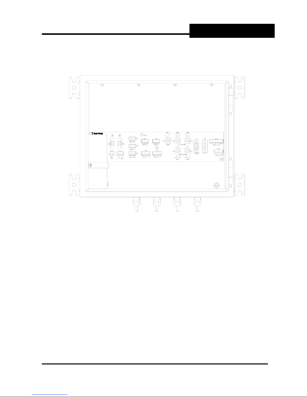
Fig 2 Sarasota 200 with lid open showing internal components
This view shows the connection panel protruding from the protective cover and the internal
battery in the bottom left corner.
The connection panel is part of the mother board which contains the input, output and power
management functions. It supports the main processor (CPU) card and the transducer
interface (TIF) card which plug in beneath the protective cover. The connection panel is
shown on a larger scale in Fig 3.
The internal battery allows operation to continue when the external power source has failed.
This is an optional facility which may only be fitted for certain external power sources. See
section 2.3.2.1.1
Section 2, SYSTEM COMPONENTS, Page 2-4
Thermo Fisher Scientific
Sarasota 200 Ultrasonic Multipath
Flowmeter
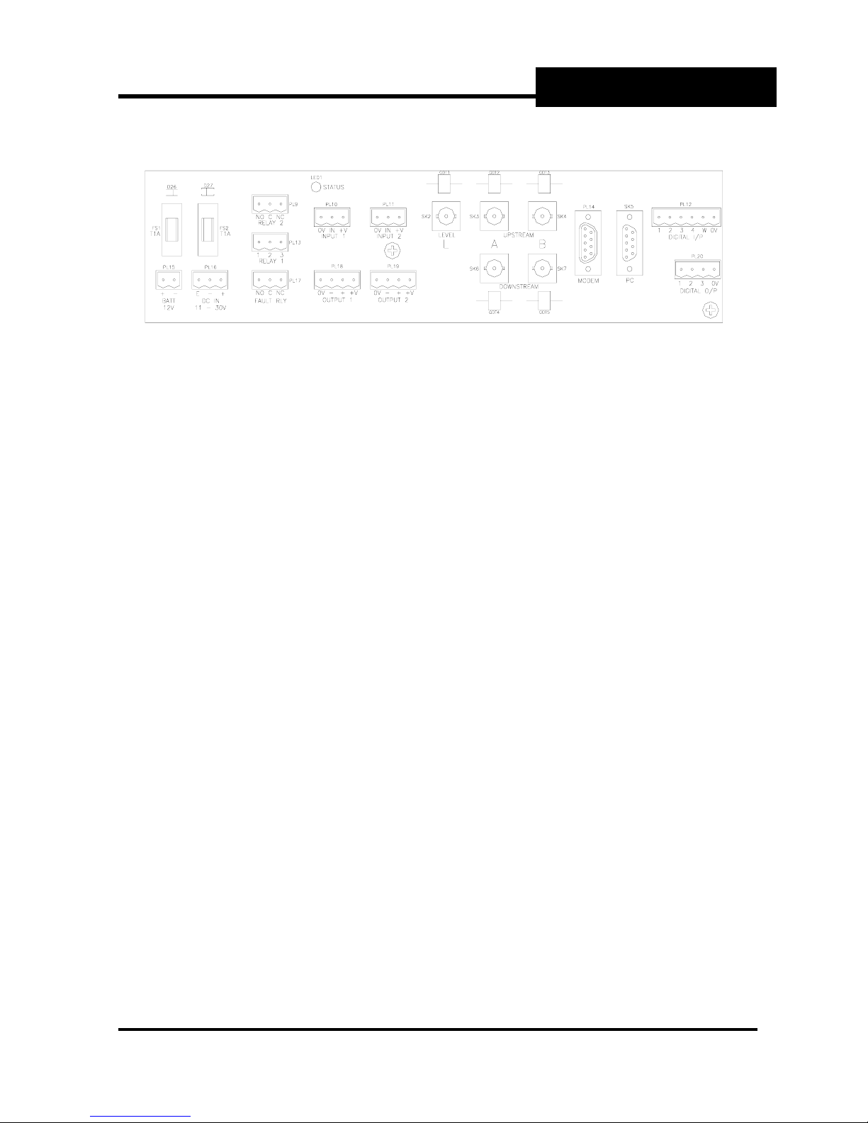
Fig 3. Connection panel - enlarged view.
This panel is where all the connections are made and where the power fuses are located.
Before making any connections the external power source and the internal battery (if fitted)
should be unplugged. The connections are in groups from left to right:
Power connections. See section 2.3.2.1.1
• PL15 – BATT. 2 pin plug for connection to the internal 12volt battery if one is to be fitted.
• PL16 – DC IN. 3 pin plug for connection to the external dc supply.
• Fuses FS1 and FS2
Relay connections. See Specification, Appendix 2
• PL9 – RELAY 2 - VFC, 3 pins, NC, Common and NO
• PL13 – RELAY 1 - SOLID STATE, 3 pins. See Appendix 2
• PL17 – FAULT RLY, 3 pins, NC, Common and NO
Status LED
Inputs See section 2.3.2.1.3
• PL10 – INP 1. 3 pin plug, 4-20 mA
• PL11- INP 2. 3 pin plug, 4-20 mA
Outputs See section 2.3.2.1.4
• PL18 – OUT 1. 4 pin plug, 4-20 mA
• PL19 – OUT2. 4 pin plug, 4-20 mA
Ultrasonic transducer connections. See section 2.3.2.1.2
• SK2 – LEVEL (L). BNC coaxial socket for ultrasonic water level transducer(s) if fitted.
• SK3 – UPSTREAM (A). BNC coaxial socket for upstream velocity transducer(s)
• SK6 – DOWNSTREAM (A). BNC coaxial socket for downstream velocity transducer(s)
• SK4 – UPSTREAM (B). BNC coaxial socket for upstream crossed path velocity
transducer(s) if fitted.
• SK7 – DOWNSTREAM (B). BNC coaxial socket for downstream crossed path velocity
transducer(s) if fitted.
Communications See section 2.3.2.1.7
SK5 – PC. 9 way D socket for RS232 serial link to PC
PL14 – MODEM. 9 way D plug for RS232 serial link to modem.
Digital See section 2.3.2.1.6
PL12, External connection W to 0V to wake up if in intermittent (external control) mode.
PL12 1 to 4 and PL20 – not used.
SYSTEM COMPONENTS
Section 2, SYSTEM COMPONENTS, Page 2-5
Thermo Fisher Scientific

Sarasota 200 Ultrasonic Multipath
Flowmeter
2.3.2 Internal components
The enclosure houses the following components
• Mother board with power connections, connectors for transducers and peripheral devices.
• Internal battery option.
• Transducer interface card
• Central processor card, with data storage, input/output and communications circuits
• LCD display
2.3.2.1 Mother board
2.3.2.1.1 Power supply and internal battery option
The power supply input is 11 to 30 Volts DC (see specification in Appendix 2)
For operation from an AC source, an external adapter is required.
If the DC input is 15 Volts or more, the internal battery option may be fitted to allow operation
to continue in the event of power failure. The internal battery is automatically charged by the
power supply when external power is being supplied.
Power consumption and the period of operation from the internal battery option depend on the
mode of operation and are given in the specification.
The fuse values are both T1A.
2.3.2.1.2. Transducer connections
For an in-line configuration of velocity paths there will be 2 star junction boxes, 1 for each
transducer array. The coaxial cable from the upstream star box terminates at SK3. The
coaxial cable from the downstream star box terminates at SK6.
For a crossed configuration of velocity paths there will be 4 star junction boxes, 1 for each
transducer array. The coaxial cable from the upstream left star box terminates at SK3 and the
downstream right at SK6. The coaxial cable from the upstream right star box terminates at
SK4 and the downstream left at SK7.
If an upward facing depth transducer is being used, the coaxial cable from it terminates at
SK2.
SYSTEM COMPONENTS
Section 2, SYSTEM COMPONENTS, Page 2-6
Thermo Fisher Scientific
 Loading...